*e-mail: [email protected] Recebido: 27/11/2011 / Aceito: 17/04/2012
Femoral stem-bone interface analysis of logical uncemented stem
Leandro de Freitas Spinelli*, Carlos Alberto de Souza Macedo, Carlos Roberto Galia, Ricardo Rosito, Fernando Schnaid, Leandro Luis Corso, Ignácio Iturrioz
Abstract This paper evaluates the mechanical behavior of an uncemented hip stem using inite element analysis. The analysis is focused on the stem-bone interaction which is assessed by simulation of distinct conditions encountered daily on orthopedic practice of hip implants. Logical uncemented femoral stem was used in this work. Three distinct conditions have been modeled: a) exposed neck with fully embedded ins, b) partially exposed anti-rotational ins and c) fully exposed ins, representing real femoral hip conditions. Anthropometric variations and different angulations for the stem neck were investigated for typical body weight of populations submitted to implants. The ratio of mobilized stress to yield stress is shown to be lower than 55% indicating a safety factor against stem failure. Although small displacements are observed in all conditions, the displacement increases with the increase of both the length of exposed ins and the magnitude of applied forces. Even for the extreme condition of fully exposed ins, the prostheses will support the working loads, and the risk of bone fracture still has a safety factor. Stresses and displacements change considerably with neck angulations suggesting that anthropometric variations should be considered in the future to optimize prostheses performance. Numerical analysis of the used uncemented femoral stem demonstrated that small stresses and strains are generated under working load conditions indicating that a proper factor of safety is obtained for the static conditions tested in the present study.
Keywords Numerical analysis, Hip surgery, Uncemented stem, Prosthesis.
Análise numérica do comportamento biomecânico da haste femoral
não-cimentada Logical
Resumo A presente pesquisa avalia o comportamento mecânico da haste femoral não-cimentada Logical através de
elementos initos. Foram analisadas diferentes condições de contorno encontradas na prática ortopédica:
a) apenas o colo exposto; b) com as aletas anti-rotatórias parcialmente expostas; e c) com as aletas totalmente
expostas. Variações antropométricas foram consideradas pelas diferentes angulações de colo propostas e através de diferentes cargas aplicadas. A haste apresentou um bom coeiciente de segurança. Embora pequenos deslocamentos sejam observados em todas as condições, existe um maior deslocamento com o aumento da exposição das aletas da prótese. Mesmo para a condição extrema com as aletas totalmente expostas, a prótese suporta as cargas de trabalho e ainda há um bom fator de segurança. Tensões e deslocamentos se modiicam consideravelmente com as diferentes angulações propostas para o colo, sugerindo que as variações antropométricas devam ser consideradas no futuro para otimizar o desempenho da prótese.
Palavras-chave Análise numérica, Cirurgia do quadril, Haste femoral não-cimentada, Prótese de
Introduction
Due to the high success rates of orthopedic surgery procedures, total hip joint replacement has increased signiicantly over last decades mainly due to population ageing. Surgery is recommended in several cases of hip damage when the damaged cartilage and bone are removed from the hip joint and replaced with new man-made parts. This imposes the challenge of carrying out biomechanical studies that are aimed at evaluating the performance of metal alloys, high-grade plastics and polymeric materials to produce highly functional and long-lasting prosthesis. Part of these studies can be done by inite element analysis used to simulate hip joint replacement performance.
A hip implant is designed to substitute an anatomical proximal femoral and acetabular part and therefore must consider parameters such as: stem length, cross-section, neck length, and neck angle, biocompatibility of materials (Bennet and Goswami, 2008). This is to ensure that the femoral stem and cups can functionally resist as a hip articulation to be used primarily in arthroplasty, revisions and reconstruction of proximal femur (Macedo, 2007). Among several other advances in the design, construction and implantation of artiicial hip joints, attentions is given to the irst Brazilian cementless stem validated by both International and Brazilian national standards (ASTM and ABNT/NBR) designed by Macedo (2007) and Macedo et al. (2008). This stem has been widely used in the Faculty Hospital of the Federal University of Rio Grande do Sul, southern Brazil, with more than 1000 units implanted, and 7100 units in Brazil. Also, the stem is a low-cost option for use in Brazilian Public Medical Assistance (SUS).
Since the clinical success of an implant is largely determined by the manner in which the mechanical forces are transferred from the implant to the surrounding bone without generating plastic stresses and permanent strains (that would risk its long-term performance), there is a need to estimate the biomechanical transfer forces involved in the design of the implant. The inite element method is known to be a valuable tool to simulate many biomechanics applications, including orthopedics, as already demonstrated by reported design experiences on joint replacement prostheses carried out either by manufacturers or by university laboratories (Brekelmans et al., 1972; Macedo et al., 2008; Prendergast, 1997). After early efforts from Brekelmans et al. (1972) reporting the irst inite element analysis (FEA) of the femur, 3D FEA has been successfully used to evaluate several different prostheses (Bennet and Goswami, 2008; Fagan and Lee, 1986; Huiskes and Van Rietbergen, 1995; Keaveny and Bartel, 1993; McNamara et al., 1997; Prendergast et al., 1989; Tanner et al., 1995;
Verdonschot, 1995; Verdonschot et al., 1993; Yettram, 1989), as well as to optimise designs (Fernandes et al., 2004; Yu et al., 2002). Sakai et al. (2010) investigated some aspects related to initial stability after stem ixation by inite element models on cementless stem. Relative micromotion of the cementless stem showed a value as low as that of a conventional stem. The authors concluded that based on the relative micromotion and von Mises stress level, the cementless stem showed initial stability.
Although numerical analysis is not fully incorporated to medical studies, there are a number of valuable contributions. Huiskes and Vroemen (1986) introduced the concept of pre-clinical evaluation by previewing maximum normal stress and shearing of interfaces for different prostheses models, whereas Brown and Callaghan (2008) revised the impingement and its dislocations by inite element method, focusing on implant variables, its implantations and patient’s activities. Ahmet et al. (2007) investigated contact mechanics and stress distribution in resurfacing with metallic cups. Kluess et al. (2009) presented an algorithm based on analyzed bone by computed tomography of an implant model to simulate bone stress and interface implant mechanisms. A human frozen hemi-pelvis was analyzed with an acetabulum implant with loading cycles measurements compared to inite element models, showing strong correlation between measured and estimated deformations.
As for the bone, simulation is differently from other biological tissues. Modeling and simulation are well established given to its relatively high stiffness and straight forward application in static solid modeling. Although some research groups have deined the geometry of the bone in a generic manner using measurements from in vitro specimens, it is becoming more common to extract bone geometry from medical scans such as computed tomography (CT) and magnetic resonance imaging (MRI) images (Jones, 2009).
Having described these early reported experiences, it is important to clarify that FEA may not produce a precise assessment of mobilized operational forces, but it does provide means of performing parametric studies conceived to optimize the geometric characteristics of an implant for a given set of material parameters (Huiskes, 1991; Lee, 1987; Prendergast, 1997). For this reason this approach has been adopted in the present work to evaluate the biomechanical behavior of an uncemented designed femoral stem.
Materials and Methods
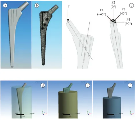
characteristics and tested performance. The designed stem presents some features of the original CLS Spotorno hip stem (Zimmer, Switzerland) and is very similar to AI-Hip cementless stem (Aimedic, Italy) used by Sakai et al. (2010), with a characteristic quadrangular and cuneiform stem with ins in the two symmetrical faces that have been designed to provide a better stem-bone interaction and tortional stability. One advantage of the Logical CM is related to the thinner and sharper blades designed to produce a better cementless ixation to the bone: blades are covered by plasma-spray porous coating with a unique microporosity to promote adequate surface for bone ingrowth (Macedo, 2007; Macedo et al., 2008) (Figure 1). The stem is made in Titanium Ti6Al4V ELI Alloy according to ASTM F136 (American..., 2008a) and NBR-ISO 5832-3 (Associação..., 1997) recommendations. The stem neck is positioned in neutral and cervical-diaisary angle of 135° having a Morse cone of 12-14 mm to allow 22, 26 and 28 mm modular femoral head diameters to be connected to short, medium and large neck lengths.
The material properties for the implant were assumed to be isotropic and linear elastic, obeying Hooke’s Law. The implant was assumed to transmit all absorbed energy to the surrounding environment and the effects of body heat were neglected to cause any creep effects. For this analysis, sizes of head diameter have not been modeled which implies on considering that forces are applied at its natural position at the femoral neck. This simple model is easily implemented and has been proved eficient in the simulation of biomechanical problems. More complex models incorporating anisotropy will be considered in future work. From the mathematical point of view, the Von Mises criteria was used to compute normal and shear stresses, which is a classical approach in the engineering ield specially to estimate the yield stress. Mesh-reinements schemes have been tested in points of greater stress increase and numerical results obtained from the analysis show displacement and stress convergence everywhere in the joint.
The way the implants are treated and modeled in this paper deserves careful consideration. The anatomical condition of a particular patient can be obtained by computer tomography (CT) images
and matrices, from which bone mineral density is captured. Although these three-dimensional imaging data can be converted into inite-element meshes for continuum mechanics computation of speciic biomedical problems, a more general approach was adopted here by simulating general conditions that are commonly encountered in daily orthopedic practice. When the natural condition of a hip is changed by prostheses, the cancellous bone is milled and removed and the femoral stem is introduced by press it. Femoral osteotomy is currently used for arthroplasties, as the prosthesis is generally fully inserted with only the neck of the femur exposed (Figura 2a). This Figure 2a presents a hip radiograph and the relationship between proximal bone and femoral stem just after the surgical procedure, showing the direct contact area between the implant surface and the cortical bone. There are cases, however, in which this standard condition is not achieved, when the femur anatomy is unusual due to small or large bone defects. In order to keep the biomechanics of the hip, it is necessary in these cases to partially expose the stem to avoid limb shortening (Figure 2b). In extreme cases, when there are large bone defects, revision prosthesis, endoprosthesis or even a standard prosthesis can be used (Figura 2c). This complex boundary conditions can be simpliied allowing the system to be modeled by taking only two materials into consideration (cortical bone and the implant), the bone being assumed as isotropic and linear and the implant inserted in a homogeneous cylindrical bone vessel (Figures 3d-f).
The model for stress and displacement analyses was meshed with three dimensional, 10 node tetrahedral solid elements. Both of bone and implant meshes were assumed to be in contact with each other by means of using adjoining nodes for each of the meshes. Material properties of the hip implant and the bone are summarized in Table 1.
The prototype implant has been designed in Autocad (Autodesk, Inc.) (Figure 1a) and SolidWorks (Dassault Systèmes, SolidWorks Corp.) (Figure 3a) to allow for an accurate discretization in a 3D inite element mesh representation, as illustrated in Figure 3b. The numerical analysis has been performed in Finite Element Method using the commercial Package ANSYS 10 (ANSYS, Inc.). This model was build
Table 1. Mechanical properties of bone and stem.
Material Elastic modulus (MPa) Critic limit (MPa)1 Poisson’s ratio
Stem (Ti6Al4V)2 134300 930 0.36
Bone3 10000 224 0.20
with 36585 tetrahedral elements with 10 nodes per element and three degree of freedom per node. 28439 elements were used to model the stem and 8146 the cylindrical vessel that represent the bone where the implant is itted. Perfect contact between implant and bone is assumed. Since typical patient’s weight lies within 50 to 120 kg, forces applied to
stem ranged from 500 to 4800 N to simulate natural conditions found in vivo (Figure 3c), considering that total hip force may reach four times body weight in special circumstances (Harkess and Crockarell, 2007; Lewis et al., 2010). Hip, as any other joint in human body, presents a complex force system whose intensity, point of application and direction depends
a b c
Figure 2. Observed X-ray hip conditions usually found in orthopedic practice: a) only neck exposed; b) partially exposed ins; and c) fully
exposed ins.
Figure 1. Uncemented femoral stem used for the experiments: a) design sketch for the Logical CM stem (sizes are in millimeters and angles in degrees); b) actual stem.
a
on many variables. In addition, the resulting force varies throughout the whole gait cycle. It can even be possible, theoretically, that the maximum stress occurs out of the maximum load zone. Some special conditions varying force directions were applied for that consideration simulating lexion-extension (lexion of +90 degrees up to extension of –45 degrees).
Three distinct conditions have been modeled, as discussed before, for the real conditions simulations: a) exposed neck with fully embedded ins, b) partially exposed anti-rotational ins, and c) fully exposed ins (Figure 3d-f), representing real femoral hip conditions seen in Figure 2. When an arthroplasty is performed for the irst time in arthrosis, near to normal anatomical conigurations are seen, once fractures or other diseases did not perturbed the bone. However, the presence of a deicient or mechanically compromised proximal femur represents a particular challenge to surgeries in the cases of dysplasia, fractures, tumors or revision total hip arthroplasty, once a lack in bone stock is observed. Although a complete ixation cannot be achieved in cases where the proximal femur is absent, there is still a chance of success in these dificult conditions (Figures 2b, c). In extreme cases, the implant would be ixed distally, acting as a ixed and embedded beam. These various conditions of femoral exposure have been evaluated
in the current study by assessing whether the lack of proximal bone alters the transfer forces to the stem.
Despite being an important topic, osteointegration was not the focus of this work, but the immediate post-operative condition, given the fact that many surgeons allow the immediate bearing support of patients in the days following surgery. Considering the subsequent osteointegration, theoretically there would be an improvement in the boundary conditions.
In addition, there are also some cases where the prostheses design may have to adapt to the patient anatomy. Since most patients have a cervix-diaphisary angle ranging from 110° to 160°, single ixed angle prosthesis may induce post-surgery apparent leg discrepancies with functional and esthetical problems. Anthropometric variations were considered by introducing modiications to the neck angulations. Different neck angular variations were analyzed, ranging from 110° to 160° (Figure 4), in order to evaluate this anthropometric conditions and their effects on transmitted stresses and displacements.
Results
The irst set of results refers to forces applied to the femoral neck which are transmitted to the implant and bones. Relationships between applied force and
Figure 3. a) 3d SolidWorks generated stem; b) inite element mesh; c) force application/orientation observed in frontal and lateral views; d,
e and f) numerical model of stem and cylindrical vessel that represent the bone for the three evaluated conditions.
a b c
maximum Von Mises Equivalent Stresses are illustrated in Figure 5a, showing that the slope of stresses increases with increasing length of exposed ins.
The static analysis with inite element method provides not only stress distribution but the stress-displacement response of the prostheses, as
shown in Figure 5b. In this igure it is possible to observe that for a given force, displacements increase with the increase of exposed ins. In the three studied conditions the maximum mobilized displacement is of the order of 20 to 100 × 10-5 m to a maximum applied force of 4800 N.
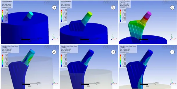
An example of the stress-displacement distribution along a cross-section of the hip stem for an applied load of 1200 N is illustrated in Figure 6. The upper line Figures 6a-c represents the displacement ield whereas the lower line Figures 6d-f shows the Von Mises Equivalent Stress ield distribution. By analyzing all three conditions, stem with exposed ins (simulating an endoprostheses) showed total deformations progressively occurring from neck base to distal prostheses. When evaluating the mobilized stresses, a stress ield concentration is observed at the contact of the neck region and the bone interface for the condition of neck exposed only (Figure 6d). Stresses
Figure 4. Extra neck angulations designed to simulate anthropometric
variations (commercial prostheses is 135°).
a b
Figure 5. Relationship between: a) applied forces and maximum Von Mises Equivalent Stress; and b) applied forces and maximum stem displacement.
a b c
d e f
Figure 6. Example of numerical results in terms of total deformations (a, b, c) and Von Mises Equivalent Stress (d, e, f) for the three conditions
Equivalent Stress and maximum calculated displacement respectively. A non-linear relationship is observed in all cases with applied forces generally increasing with reducing neck angulation. For neck angulations lower than 135°, the exposed ins condition generates stress that is higher for a fully embedded neck. A completely buried prostheses generates mobilized stress lower than 10 × 107
Pa yielding total deformations as small as 5 × 10⁻⁵ m.
Partially or totally exposed ins show almost no stress distribution differences, but the displacements increase signiicantly for the case of totally exposed ins. Variations on total deformations range from 5 to 15 × 10–5 m and
20 to 30 × 10–5 m for partially or totally exposed ins,
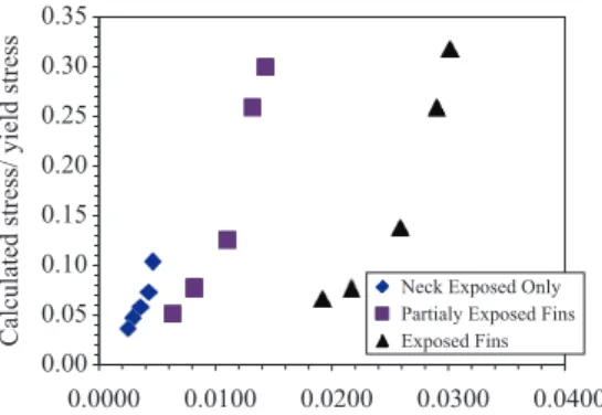
respectively (Figure 8b). These values can be represented in a normalized fashion as illustrated in Figure 7 to yield data shown in Figure 9. A non-linear relationship is observed for all studied cases, showing that a given normalized stress and normalized displacements increase considerably with increasing exposition of ins.
Discussion
Forces applied to the femoral neck are transmitted to the implant and bones, and the slope of stresses and displacements increases with increasing length of exposed ins. In practice, however, there are no major differences among the three cases because the mobilized stress is about 50% of the laboratory measured yield stress. This ind is on itself an essential feature in the hip design, because the implant is dynamically loaded and severe fatigue damage can be produced. Since this study is concentrated on static loading, the static result can be used to evaluate the fatigue life of the component if inertial effects are neglected.
When evaluating the mobilized stresses, the stress ield concentration is different for the three conditions proposed in this work. The linear stress-strain has a maximum stress ratio of about 0.55 indicating a are distributed over a larger area throughout prostheses as
ins became exposed (Figure 6e). Two points of higher stress were observed when ins were totally exposed (Figure 6f), which are located at the neck and at the transition to the bone. In the condition of an exposed neck, stress concentration is only at the neck bases whereas other conditions show a progressive stress towards the transition to the bone. This described behavior becomes clear in Figure 7, in which normalized displacements are plotted against normalized Von Misses Equivalent Stress. The yield stress and corresponding critical displacement have been measured by uniaxial compressive laboratory tests (Macedo, 2007; Macedo et al., 2008). A linear normalized stress-strain relationship is observed in this igure with a maximum stress ratio of about 0.45 for the most commonly used coniguration indicating a high factor of safety under static loading. Even for the worst condition, stress ratio is about 0.55.
When gait cycle is considered, the worst condition is for 90 degrees lexion. Standard use (only neck exposed) reaches 0.54, still having a good safety factor, whereas partially exposed ins reaches 0.81 and totally exposed reaches 0.83.
Figures 8a, b present the relationship between stem neck variation with maximum calculated Von Mises
Figure 7. Normalized Von Mises Equivalent Stress/Yield Stress versus normalized calculated displacements/Maximum Displacements.
a b
good factor of safety under static loading. Although maximum normalized displacements are lower than 0.12 for the worst conditions, displacements increase considerably for the condition of exposed ins, which may increase future risk of bone fracture. The numerical analysis has not modeled fracture effects, since it would depend on bone mineral density and in this case bone anisotropy, directions and magnitude of transmitted forces, prostheses migration and rotation, among other factors, should be considered on the numerical model.
A non-linear relationship was observed in all cases when neck angles variations were considered. Normalized stress and normalized displacements increase considerably with increasing exposition of ins. Moreover, mobilized stresses and displacements are lower for the valgus condition (160°) and increase as the prostheses became varus (110°), as illustrated in Figure 4.
The stress distribution on the bone interface has important implications. Higher Young Modulus stems transfers less stresses to the bone, inducing stress-shield effect, and increasing applied forces transfers higher stresses to the bone, as well for increasing exposed ins. This information is better understood when calculated values are normalized by the bone ultimate stress of 224 MPa (see Table 1), yielding a maximum normalized stress of about 50%. Anthropometric variations studied in this research program indicated similar patterns for 110° to 160°.
Although numerical analysis is a highly specialized subject, an attempt was made to narrow the gap between specialized researchers and practicing medical doctors, who may not be familiar with detailed numerical methodologies but have the need to incorporate new concepts into design to provide safer and more economical prostheses. First it is
important recognizing that computational analysis is now becoming accepted in biomechanics as a mean of decreasing the number of individuals needed in research, as well as to decrease costs in developing prototype prostheses. ASTM F2514-08 (American..., 2008b), Standard Guide for Finite Element Analysis of Metallic Vascular Stents Subjected to Uniform Radial Loading, is an example.
The femoral hip design investigated in the present study complies with medical standards (ASTM and ISO/ABNT/NBR Standards) and has gone through a series of rigorous tests before being commercially launched. Finite element analysis provide means of optimizing the hip prostheses design and perform pre-clinical evaluation (Huiskes and Vroemen, 1986; Huiskes et al., 1977), as presented in this research.
Conclusions
Numerical analysis of Logical uncemented femoral stem demonstrated that current design successfully meets speciic project goals and objectives. Small stresses and displacements are generated under working load conditions to the stem indicating that a proper factor of safety is obtained for the static conditions tested in the present study. The stem performance is shown to be fairly sensitive to both the length of exposed ins and the neck angle variation. These evidences give room to a number of recommendations. Stem displacements increase signiicantly with the increase length of exposed ins, and even for the extreme situation of totally exposed ins, the prostheses will support the working loads, but the risk of bone fracture may increase due to increasing displacements.
The sensitivity to neck angulations indicates that anthropometric variations should be considered in order to obtain best functional results. In addition to pre-clinical testing, patient-speciic models may have a future potential to be used directly in clinical practice and on patient management in a number of ways, including assessment of the mechanical aspects preoperatively, select appropriate devices for each biological and non-biological variability (material properties, design options, geometry), predict load transfer stress distribution after surgery and estimate long term performance of the procedure.
Acknowledgements
This research program has been developed at the University Hospital at Federal University of Rio Grande do Sul, Brazil. The numerical study was supported by the Civil and Mechanical Post-Graduation
Figure 9. Normalized calculated Von Mises Equivalent Stress/
Yield Stress versus normalized calculated displacements/Maximum
Program at the same university, being supported by Brazilian National Program for Post-Doctoral AUX-PE-PNPD:1517/2008. The authors also would like to thanks to Dr. Luis Fernando Moreira for his important contribution to the research.
References
Associação Brasileira de Normas Técnicas - ABNT. ABNT NBR ISO 5832-3: Implants for surgery - Metallic materials Part 3: Wrought titanium 6-aluminium 4-vanadium alloy. ABNT; 1997. Ahmet CC, Ucar V, Kazan R. Three-dimensional anatomic inite element modelling of hemi-arthroplasty of human hip joit. Trends in Biomaterials & Artiicial Organs. 2007; 21:63-72. American Society for Testing and Materials - ASTM. ASTM F136-08e1: Standard speciication for wrought Titanium-6 Aluminum-4 Vanadium ELI (Extra Low Interstitial) alloy for surgical implant applications (UNS R56401). West Conshohocken: ASTM International; 2008a. 5 p. American Society for Testing and Materials - ASTM. ASTM F2514-08 - Standard guide for inite element analysis of metallic vascular stents Subjected to uniform radial loading. West Conshohocken: ASTM International; 2008b. 8 p. Bennet D, Goswami T. Finite element analysis of hip stem designs. Materials and Design. 2008; 29:45-60. http://dx.doi. org/10.1016/j.matdes.2006.12.014
Brekelmans WAM, Poort H, Slooff TJJH. A new method to analyse the mechanical behaviour of skeletal parts. Acta Orthopaedica Scandinavica. 1972; 43(5):301-17. http:// dx.doi.org/10.3109/17453677208998949
Brown TD, Callaghan JJ. Impingement in total hip replacement: mechanisms and consequences. Current Orthopaedics. 2008; 22:376-91. PMid:19956356 PMCid:2652485. http://dx.doi.org/10.1016/j.cuor.2008.10.009 Fagan MJ, Lee AJC. Material selection in the design of the femoral component of cemented total hip replacements. Clinical Materials. 1986; 1:151-67. http://dx.doi.org/10.1016/ S0267-6605(86)80029-4
Fernandes PR, Folgado J, Ruben RB. Shape optimization of a cementless hip stem for a minimum of interface stress and displacement. Computer Methods in Biomechanics and Biomedical Engineering. 2004; 7(1): 51-61. PMid:14965880. http://dx.doi.org/10.1080/10255840410001661637 Harkess JW, Crockarell JR. Arthroplasty of the hip. In: Canale ST, Beaty JH, editors. Campbell’s Operative Orthopaedics. 11th ed. Philadelphia: Mosby Elsevier; 2007. chap. 7, 314 p.
Huiskes R. Biomechanics of artiicial-joint ixation. In: Mow VC, Hayes WC, editors. Basic orthopaedic biomechanics. New York: Raven Press; 1991. p. 375-442.
Huiskes R, Slooff TJJH, Elangovan PT, Banens JPA. Finite element computer methods for design and ixation problems of orthopaedic implants. Computer Methods in Biomechanics and Biomedical Engineering. 1977; 229-38.
Huiskes R, Van Rietbergen B. Preclinical testing of total hip stems: the effects of coating placement. Clinical Orthopaedics and Related Research. 1995; 319:64-76. PMid:7554651. Huiskes R, Vroemen WA. A standardized inite element model for routine comparative evaluations of femoral hip prostheses. Acta Orthopaedica Belgica. 1986; 52:258-61. PMid:3788510.
Jones AC. Introduction to inite element analysis. Leeds: Finite Element Analysis for Orthopaedic Design; 2009. Keaveny TM, Bartel DL. Effects of porous coating with and without collar support, on early relative motion for cementless hip prostheses. Journal of Biomechanics. 1993; 26:1355-68. http://dx.doi.org/10.1016/0021-9290(93)90087-U Kluess D, Souffrant R, Mittelmeier W, Wree A, Schmitz K-P, Bader R. A convenient approach for inite-element-analyses of orthopaedic implants in bone contact: modelling and experimental validation. Computer Methods and Programs in Biomedicine. 2009; 95(1):23-30. PMid:19231021. http:// dx.doi.org/10.1016/j.cmpb.2009.01.004
Lee AJC. Finite element analysis and its signiicance in total hip replacement. In: Stillwell WT, editor. The art of total hip arthroplasty. Orlando: Grune & Stratton; 1987. p. 33-9. Lewis CL, Sahrmann SA, Moran DW. Effect of hip angle on anterior hip joint force during gait. Gait & Posture. 2010; 32(4):603-7. http://dx.doi.org/10.1016/j. gaitpost.2010.09.001
Macedo CAS. Developing national cementless stem, validated by international standards [thesis]. Porto Alegre: Federal University of Rio Grande do Sul; 2007. 121 p.
Macedo CAS, Galia CR, Moreira LF, Rosito R, Macedo FCS, Hübler R. Characterization of a cementless Ti-6Al-4V femoral stem. Brazilian Journal of Biomedical Engineering. 2008; 24(3):183-92.
McNamara BP, Taylor D, Prendergast PJ. Computer prediction of adaptative bone remodelling around noncemented femoral prostheses: the relationship between damage-based and strain-based algorithms. Medical Engineering & Physics. 1997; 19(5):454-63. http://dx.doi.org/10.1016/ S1350-4533(97)00002-7
Prendergast PJ. Finite element models in tissue mechanics and orthopaedic implant design. Clinical Biomechanics. 1997; 12(6):343-66. http://dx.doi.org/10.1016/ S0268-0033(97)00018-1
Prendergast PJ, Monaghan J, Taylor D. Materials selection in the artiicial hip joint using inite element stress analysis. Clinical Materials. 1989; 4:361-76. http://dx.doi. org/10.1016/0267-6605(89)90016-4
Sakai R, Sato Y, Itoman M, Mabuchi K. Initial ixation of a inite element model of an AI-Hip cementless stem evaluated by micromotion and stress. Journal of Orthopaedic Science. 2010; 15:132-9. PMid:20151263. http://dx.doi. org/10.1007/s00776-009-1422-z
Physics. 1995; 17(4):291-6. http://dx.doi.org/10.1016/1350-4533(95)90854-5
Verdonschot NJJ. Biomechanical failure scenarios for cemented total hip replacement [thesis]. The Netherlands: University of Nijmegen; 1995.
Verdonschot NJJ, Huiskes R, Freeman MAR. Pre-clinical testing of hip prosthetic designs: a comparison of inite element calculations and laboratory tests. London: The Institute of Mechanical Engineering; 1993. p.149-54.
Yettram AL. Effect of interface conditions on the behaviour of a Freeman hip endoprosthesis. Journal of Biomedical Engineering. 1989; 11:520-4. http://dx.doi.org/10.1016/0141-5425(89)90048-4
Yu SH, Ville JST, Rajan SD. Inverse design techniques for improving composite prosthetic devices. Engineering Optimization. 2002; 34(5):427-43. http://dx.doi. org/10.1080/03052150214018
Authors
Leandro de Freitas Spinelli*
Post-Doctoral Program in Engineering, Federal University of Rio Grande do Sul – UFRGS,
Fellowship Program in Hip Surgery, Clinics Hospital, Federal University of Rio Grande do Sul – UFRGS, Rua Ramiro Barcelos, 1323/701, CEP 90035-006, Porto Alegre, RS, Brazil
Carlos Alberto de Souza Macedo, Carlos Roberto Galia, Ricardo Rosito
Department of Orthopedics, Faculty Hospital, Federal University of Rio Grande do Sul – UFRGS, Rua Ramiro Barcelos, 2350, Largo Eduardo Zaccaro Faraco, CEP 90035-003, Porto Alegre, RS, Brazil
Fernando Schnaid
Department of Civil Engineering, Federal University of Rio Grande do Sul – UFRGS, Av. Osvaldo Aranha, 99/3º andar, CEP 90035-190, Porto Alegre, RS, Brazil
Leandro Luis Corso, Ignácio Iturrioz