The use of composite materials based on polymeric resins and iber as strengthening in concrete structures has been widely used. The use of carbon iber reinforced polymers or other synthetic ibers is consolidated by its excellent characteristics, such as high strength, low weight, corro -sion resistance, etc. This material in the form of sheets or laminates is bonded to the concrete substrate with epoxy-based adhesives. Although epoxy has proven to have excellent bonding and resistance performance, it has some disadvantages, such as low permeability, poor thermal compatibility with the base concrete, poor ire resistance, etc. Cement-based composite systems consisting of FRPs and a cementitious bonding agent can be used to prevent some of these problems. This study presents the numerical analysis, using a non-linear inite element model, of the structural behavior of reinforced concrete beams externally reinforced with a composite material made of high-strength synthetic iber mesh and cementitious mortar. The numerical results were compared with experimental results reported in international journals, demonstrating the ef -iciency of the strengthening technique and the numerical model capacity.
Keywords: numerical analysis, ultra-high strength iber meshes, cementitious mortar, structural strengthening.
A aplicação de materiais compósitos à base de resinas poliméricas e ibras no reforço de estruturas de concreto armado se tornou uma técnica bastante difundida nos últimos tempos. O uso dos compósitos reforçados com ibras de carbono, ou outros tipos de ibras sintéticas, se conso -lidou pelas suas excelentes características, tais como elevada resistência, baixo peso, resistência à corrosão, etc. Este material, na forma de lâminas ou laminados, é colado no substrato de concreto através de adesivos à base de epóxi. Apesar do uso do epóxi apresentar excelentes re -sultados em termos de colagem e resistência, algumas desvantagens podem ser citadas, tais como: baixa permeabilidade, baixa compatibilidade térmica em relação ao concreto, baixa resistência ao fogo, etc. Para evitar alguns desses problemas, um sistema compósito à base de tecidos ou malhas de ibras sintéticas coladas na superfície de concreto com argamassa de cimento pode ser usado. O objetivo deste trabalho é fazer uma análise numérica, através de um modelo não linear de elementos initos, do comportamento estrutural de vigas de concreto armado reforçadas à lexão com compósitos baseados na combinação de tecidos de ibras sintéticas de alta resistência e argamassa de cimento. Os resultados numéricos são comparados aos resultados experimentais publicados em artigos técnicos internacionais, que demonstram a eiciência da técnica de reforço e a capacidade do modelo numérico.
Palavras-chave: análise numérica, ibras de alta resistência, argamassa de cimento, reforço estrutural.
Numerical analysis of reinforced concrete beams
strengthened with high strength cement-based
composite material
Análise numérica de vigas de concreto armado
reforçadas por compósitos formados por ibras de alta
resistência e argamassa de cimento
C. M. PALIGA a
M. V. REAL b
A. CAMPOS FILHO c
a Universidade Federal de Pelotas, Departamento de Tecnologia da Construção, [email protected], Rua Benjamin Constant 1359,
Pelotas/RS, Brasil;
b Universidade Federal do Rio Grande, Escola de Engenharia, [email protected], Av. Itália km 8, Campus Carreiros, Rio Grande/RS, Brasil; c Universidade Federal do Rio Grande do Sul, PPGEC, [email protected], Av. Osvaldo Aranha 99 – 3º andar, Porto Alegre/RS, Brasil.
Received: 06 Sep 2012 • Accepted: 24 Oct 2012 • Available Online: 05 Apr 2013
Abstract
1. Introduction
Composite materials based on high-strength synthetic ibers have been widely employed to strengthen and rehabilitate reinforced concrete structures in the last few years due to their excellent properties, including low weight, high mechanical strength, high re -sistance to corrosion, etc. Fiber-reinforced polymers are available as sheets or laminates bonded to reinforced concrete structures by epoxy-based bonding agents, improving their structural perfor -mance both under service conditions and ultimate loads.
Although epoxy-based bonding agents may present excellent concrete bonding and mechanical strength, their use also poses some problems. Epoxy resins have low permeability, low thermal compatibility with concrete, low ire resistance, and high suscepti -bility to ultraviolet radiation. Some of these problems may be pre -vented using a composite system based in synthetic iber fabric or laminate bonded to the concrete surface by cement mortar. These systems can have different solutions, such as textile reinforced concrete (TRC), textile reinforced mortar (TRM), iber reinforced concrete (FRC), and iber reinforced cementitiousmortar (FRCM). Di Tommaso et al. [2] and Aiello et al. [3] analyzed the behav -ior of reinforced concrete beams externally strengthened with FRCM consisting of carbon-iber fabric in a cement matrix. The results showed that the composite system was eficient in terms of strength, stiffness, and ductility. The FRCM system was re -cently improved by the use of polypara-phenylene-benzo-bisthia -zole (PBO) iber fabric. The mechanical properties of PBO ibers are much better than those of the most resistant carbon ibers (Ombres [1]). In addition, they have high tolerance to impact, bet -ter energy absorption capacity than other ibers, as well as high resistance to ire and are chemically compatible with cement mor -tars (Wu et al. [4]).
The use of PBO iber fabrics (see Figure 1) in FRCM systems is still being investigated. Tests with concrete beams reinforced with PBO fabric bonded to concrete using cement mortar (PBO-FRCM) were recently carried out. Experimental analyses with CFRP (car
-bon iber reinforced polymers) -bonded with epoxy resin and PBO-FRCM to reinforce concrete beams were performed by Di Tomma -so et al. [5]. The following results were obtained: (i) lexure failure of the beams strengthened with PBO-FRCM was more ductile than CFRP-strengthened beams due to a gradual loss in compos -ite action caused by the slipping of ibers/cementitious mortar; (ii) in PBO-FRCM strengthened beams, failure mechanisms related to the loss of strengthening action (debonding) are determined by the concrete/cementitious mortar interface, whereas in CFRP strengthened beams, failure due to debonding is determined by shearing of the concrete cover layer; and (iii) PBO-FRCM has also shown eficient as strengthening against shear of reinforced con -crete beams.
The objective of the present study was to perform a numerical analysis of concrete beams strengthenedwith this new material (PBO-FRCM) relative to lexural strength. The numerical model is based on the inite element method, and it may follow up the re -sponse of the evaluated structure from initial loading to failure load. The model can also predict failures modes, including ductile – due to excessive elongation of the tension reinforcement or to rupture of the strengthening system – and fragile – due to concrete crush -ing or strengthen-ing system debond-ing – failures. The numerical data were compared with the experimental results obtained by Ombres [1], demonstrating both the eficacy of the strengthening material and the potentials of the numerical model.
2. Tested beam characteristics
Flexural strength of the simply supported beams was tested with two loads concentrated at 90cm from the bearing supports. Beam span was 270cm between supports, and beams presented 15x25cm rectangular cross section (Figure 2). Two beam series, designated as S1 and S2, were tested. In series S1, the tensioned reinforcement, As, consisted of three 12mm bars (3ø12mm), whereas the compressed reinforcement, A’s, consisted of two 10mm bars (2ø10mm). In series S2, the tensioned reinforcement consisted of two 10mm bars (2ø10mm), whereas two 8mm bars (2ø8mm) where used in the compressed reinforcement. In order to prevent beam shear failures, 8mm stirrups placed every 17cm were used (ø8c.17). The beams were strengthened with one, two,
Figure 1 – PBO fabric mesh
ment, which were determined in standardized specimen tests (at least three per diameter).
3. Finite element numerical model
3.1 Model for concrete
Concrete is represented by two-dimensional isoparametric eight-node inite elements for plane stressstate. The constitutive two-di -mensional model for concrete is based on the model proposed by Darwin and Pecknold [6] employing the equivalent uniaxial strain and the two-dimensional failure criterion of Kupfer and Gerstle [7]. For the tensioned concrete after cracking, a curve that includes softening was adopted to take into account concrete contribution to tension-stiffening between cracks.
3.2 Model for steel
Reinforcement is represented by the embedded model, based on the study of Elwi and Hrudey [8]. Each reinforcement bar was considered or three 15cm-wide PBO-FRCM layers. The mechanical properties
of the PBO fabric are presented in Table 1.
Table 2 shows tensile reinforcement ratio, compression ratio, and PBO ibers reinforcement ratio of each series.
During the process of beam manufacturing, curing was performed at environmental temperature, and the prototypes were strengthened 30 days after concrete placement. In order to ensure good bonding conditions between concrete and the mortar substrate, the beams were sandblasted to remove cement powder, washed with water, and left to dry at environmental temperature for a few days. After the irst mortar layer was applied on the concrete substrate, the irst layer of PBO fabric was applied and slightly pressed inside the mor -tar. A second mortar layer was then applied to completely cover the PBO fabric, and this operation was repeated until all PBO fabric lay -ers were applied and covered with mortar (Ombres [1]).
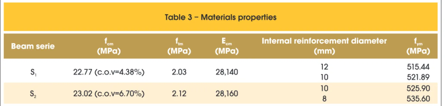
Concrete mechanical properties were determined after at least 28 days of concrete placement using cubic or cylindrical test speci -mens. Mean compressive strength, fcm, tensile strength, ftm, and
elastic modulus, Ecm, values are presented in Table 3. The same
table shows mean yield strength values of the internal reinforce
-Table 1 – Mechanical properties of PBO fabric mesh and cementitious mortar
Nominal thickness
Elastic modulus
Tensile strength
Tensile strain Compression strength
(mm)
(GPa)
(MPa)
(‰)
(MPa)
PBO fiber
mesh
0.0455 (longitudinal)
0.0224 (transversal)
270
5,800
21.5
-
Mortar
-
6
3.5
-
29
Table 2 – Amount of internal reinforcement and strengthening in each series
Beam serie
Number of strengthening layers
As
2A’s
Af
s
f(mm )
2(mm )
2(mm )
(%)
(%)
S
11
339.30
157.00
6.75
0.905
0.018
1
339.30
157.00
6.75
0.905
0.018
S
21
157.00
100.53
6.75
0.419
0.018
2
157.00
100.53
13.50
0.419
0.036
3
157.00
100.53
20.25
0.419
0.054
Table 3 – Materials properties
Beam serie
f
cmf
tmE
cmInternal reinforcement diameter
f
ym(MPa)
(MPa)
(MPa)
(mm)
(MPa)
S
122.77 (c.o.v=4.38%)
2.03
28,140
12
515.44
10
521.89
S
223.02 (c.o.v=6.70%)
2.12
28,160
10
525.90
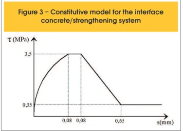
tween the two materials. These stresses may lead to the premature debonding of the PBO-FRCM system and consequent structure fail -ure with little mobilization of its resistance capacity, indicating that the material was underutilized. Slipping between reinforcement and con -crete was calculated using a six-node one-dimensional interface ele -ment with quadratic interpolation functions, according to Adhikary and Mutsuyoshi [9]. The constitutive model applied is that recommended by the CEB-FIP Model Code 1990 [10], with bond stress (
τ
) to slip (s) relationship parameters obtained by Silva [11] and shown in Figure 3.3.5 Finite element mesh used for numerical analyses
Due to the loading symmetry, mechanical properties, and geom -etry, only half of the beams were used in the numerical simula -tions. The inite element mesh used in the numerical simulations is presented in Figure 4. Concrete was discretized by 18 two-di -mensional plane stress elements, and the external reinforcement and the interface concrete/strengthening were discretized by eight one-dimensional elements.
Further details of the inite element model used in the numerical simulations are described by Paliga et al. [12].
4. Results
In this section, the results obtained using numerical simulations are presented, discussed and compared with the results of the experi -mental program (Ombres[1]). It must be mentioned that the inite element model was able to follow up beam performance from initial loading to ultimate load. The numerical model was also able to detect beam failure mode. Failure may be ductile, due to excessive elongation of the tensionedreinforcement or to failurecaused by PBO-FRCM material tension, or fragile, resulting from crushing of the compressed concrete or from PBO-FRCM systemdebonding.
4.1 Series S
1In this series, two beams were reinforced at a tension reinforcement as a stiffer line inside the concrete that resists only to axial forces.
It was assumed perfect bonding between the reinforcement and the concrete that involves it. Therefore, the reinforcement stiffness matrix has the same dimensions as the concrete element. The adopted steel constitutive equation is bilinear both for tension and compression.
3.3 Model for the strengthening composite material
The strengthening material was modeled by quadratic elements of plane truss with three nodes. The element is ixed to the remain -ing inite element mesh by an interface element. These materials are modeled as having linear elastic behavior until rupturestress is achieved, and are able to absorb only tension forces parallel to their longitudinal axis.
3.4 Model for the interface between the concrete
substrate and the PBO- FRCM system
The transference of forces between the external strengthening sys-tem and the concrete generates bondstresses at the interface
be-Figure 3 – Constitutive model for the interface
concrete/strengthening system
ratio of 0.905% (3ø12mm), compression ratio of 0.419% (2ø10mm) and strengthening ratio of 0.018% (a 6.75mm2 layer). According to
Ombres [1], rupture load of the irst prototype was 87.42kN, and fail -ure was caused by concrete crushing. The second prototype failed also due concrete crushing at 87.60kN ultimate load. The rupture load obtained by the numerical model was 86.25kN, representing an average difference of -1.4% relative to the experimental values. Figure 5 shows the load-delection curves obtained experimen -tally, which are compared with the beam performance numerically calculated.
Figure 6 shows the comparison between the experimental and the numerical values for concrete compressive strain (sample point near node 77) and for maximum strengthening tensile strain (sam -ple point near node 94).
4.2 Series S
2In this series, three numerically simulated beams were reinforced with a tension reinforcement ratio of 0.419% (2ø10mm), compres -sion ratio of 0.268% (2ø8mm) and PBO-FRCM reinforcement ratio of 0.018% (one 6.75mm2 layer), 0.036% (two 13.5mm2 layers) and 0.054% (three 20.25mm2 layers).
4.2.1 Beam strengthened with one PBO-FRCM layer
According to Ombres [1], the beam strengthenedwith one PBO-FRCM layer failed at a 54.24kN load due to concrete crushing. The ruptureload numerically obtained by inite element model was 52.25kN, representing a difference of -3.7% relative to the experi -mental value.
Figure 7 shows the load-delection curves obtained experimentally and numerically.
Figure 8 shows the comparison between the experimental and the numerical values for concrete compressive strain (sample point near node 77) and for maximum strengthening tensile strain (sam -ple point near node 94).
4.2.2 Beam strengthened with two PBO-FRCM layers
According to Ombres [1], the beam strengthened with two PBO-FRCM layers collapsedat a 66.00kN load due to the debonding of the strengthening system from the concrete substrate. The rupture load numerically obtained by inite element model was 68.75kN, rep -resenting a difference of +4.2% relative to the experimental value.
F
igure 5 – Load-deflection curves (node 73 – Figure 4)
for Beam Serie S1
Figure 6 – Load versus Strain in the mid-span
section for Beam Serie S
1Figure
7 – Load-deflection curves (node 73 – Figure 4)
Figure 9 shows the load-delection curves obtained experimentally and numerically.
Figure 10 shows the comparison between the experimental and the numerical values for concrete compressive strain (sample point near node 77) and for maximum strengthening tensile strain (sam -ple point near node 94).
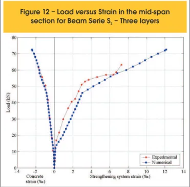
4.2.3 Beam strengthenedwith three PBO-FRCM layers
According to Ombres [1], the beam strengthened with three
PBO-FRCM layers failedat a 71.39kN load due to the debond -ing of the strengthen-ing system from the concrete substrate. The rupture load numerically obtained by inite element model was 72.75kN, representing a difference of +1.90% relative to the experimental value.
Figure 11 shows the load-delection curves obtained experimen -tally and numerically.
Figure 12 shows the comparison between the experimental and the numerical values for concrete compressive strain (sample point near node 77) and for maximum strengthening tensile strain (sample point near node 94) as a function of applied load increase.
Figure 8 – Load
versus
Strain in the mid-span section
for Beam Serie S – One layer
2Figure 9 – Load-deflection curves (node 73 – Figure 4)
for Beam Serie S – Two layers
2Figure 10 – Load
versus
Strain in the mid-span
section for Beam Serie S – Two layers
24.3 Discussion of the obtained results
Figure 13 presents the behavior of the three beams numerically analyzed in series S2 in terms of maximum delection, as a function of applied load increase.
The eficacy of the strengthened system relative to ultimate loads increased as the number of PBO-FRCM layers increased. In addi -tion, the beams presented adequate ductility levels. The concrete crushing that caused the beam with one PBO-FRCM layer to fail happened after the tensioned reinforcement yielded.
When the behavior of the strengthened beams was analyzed, it was
observed that the strongest inluence of the PBO-FRCM ratio also happens after the tensioned internal reinforcement yielded, when the strengthening system resistance capacity was effectively mobilized. It must be noted that the beam strengthened with two PBO-FRCM layers was approximately 32% more resistant than the one with only one FRCM layer, whereas the beam with three PBO-FRCM layers was approximately 6% more resistant than that with two layers. Therefore, the 50% increase in strengthening system area (from 13.5mm2 to 20.25mm2) contributed very little to increase
beam resistance. This is easily explained by the fact that these beams failed due strengthening system debonding, suggesting that increasing the number of PBO-FRCM layers may lead to pre -mature beam failure due to strengthening system debonding and therefore, the resistance capacity of this material is underutilized. Figure 14 shows the bond stresses variations along the interface concrete/strengthening system obtained numerically for the last step before rupture load of beam series S1 e S2. The level of con -crete/strengthening system bond stress for the beams strength -ened with one PBO-FRCM layer (S1 and S2 – one layer) was low
before the beams failed, indicating the failure mode was not fragile, that is, it was not caused by debonding of the strengthening from the concrete substrate. On the other hand, beams strengthened with two and three PBO-FRCM layers presented high bond stress before the beams collapsed. These stress peaks, located between 58cm and 90cm from the support, were very close to the strength of the bond between the concrete and the strengthening material, indicating that failure was caused by debonding of the PBO-FRCM system. Therefore, the failure modes determined numerically are consistent with those obtained in the experimental tests.
5. Conclusions
The structural performance of the reinforced concrete beams ex -ternally strengthenedby a high-performance system consisting of high-strength ibers in a cementitious mortar (PBO-FRCM) was
Figure 12 – Load
versus
Strain in the mid-span
section for Beam Serie S – Three layers
2Figure 13 – Load-deflection curves
numerically analyzed in this study. The obtained results allow the following conclusions.
The inite element model used for numerical simulations has shown to be a valuable tool to analyze this type of problem. Its eficiency was demonstrated when the results were compared with the ex -perimental values presented by Ombres [1]. Despite the different failure modes, the numerical model achieved an average approxi -mation of 2.8% for failure loads relative to the experimental values. The use of the PBO-FRCM system signiicantly improved the lex -ural strength of reinforced concrete beams. The results showed an increase of approximately 39% in load capacity when the external reinforcement material was applied (from 52.25kN to 72.75kN). However, increasing PBO-FRCMratios may lead to beam failure due todebonding of the strengthening system. This represents an underutilization of the strengtheningmaterial, as it cannot be submitted to maximum strain. This is shown by the increase in ap -proximately only 6% in the ruptureload of the beams with three strengthening layers (Af=20.25mm2 – P
u=72.75kN) relative to
those relationship with two layers (Af=13.50mm2 – Pu=68.75kN).
According to Ombres [1], these beams faileddue to the debonding of the PBO-FRCMsystem from the concrete substrate.
Beam ductility was adequate. Even when beams failed due to concrete crushing, this happened after the tensioned internal re -inforcement yielded.
The strongest inluence of the PBO-FRCMratio on beam stiffness happens after the tensioned internal reinforcement yielded. Before cracking, there is no inluence of the PBO-FRCM ratio on beam be -havior, as it depends almost exclusively of the stiffness of the concrete section that is still intact. After cracking load, the increase in stiffness as the number of layers increase is minimal, as the dependence of the tensioned internal reinforcement is higher. After the tensioned internal reinforcement yields, beam resistance starts to depend almost exclu -sively of the strengtheningmaterial. There is a signiicant increase in stiffness as PBO-FRCM systemarea increases.
When premature failuremodes are prevented, the simple models commonly adopted to predict resistance are capable of providing reasonably accurate approximations. However, when external strengthening PBO-FRCM systemdebonding is expected, more sophisticated models should be used to provide realistic predic -tions of the resistance capacity of strengthened beams. Therefore, numerical models based on the inite element method are very useful to analyze this type of problem.
6. References
[01] OMBRES, L. Flexural analysis of reinforced concrete beams strengthened with a cement based high strength composite material. Composite Structures, v.94, Dec, 2011; p.143-155.
[02] DI TOMMASO, A.; FOCACCI, F.; MANTEGAzzA, G. Rinforzo a lessione di travi in calcestruzzo armatto com reti di carbonio e matrice cementizia. In: Proceedings of the national AICAP conference. Italy, 2004. [03] AIELLO, M. A.; LEONE, M.; OMBRES, L. Structural
analysis of reinforced concrete beams strengthened with externally bonded FRP (iber reinforced polymers) sheets. In: Proceedings of the third international conference on “composites in constructions”, Lyon,France, 2005, p.11-8.
[04] WU, z. S.; IWASHITA, K.; HIGUCHI, T.; MURAKAMI, S.; KOSEKI, Y. Strengthening PC structures with externally prestressed PBO iber sheets. In: Proceeding of the international conference on FRP composites in civil engineering, Honk Hong, 2001, p.1085-92. [05] DI TOMMASO, A.; FOCACCI, F.; MANTEGAzzA, G.;
GATTI, A.. FRCM versus FRP composites to strengthen RC beams: a comparative analysis. In: Proceedings of the international symposium on ibre reinforced polymers for reinforced concrete structures (FRPRCS8). Patras, Greece, 2007.
[06] DARWIN, D.; PECKNOLD, D. A. Nonlinear biaxial stress-strain law for concrete. Journal of Engineering Mechanics Division, v.103, 1977; p.229-241.
[07] KUPFER, H. B.; GERSTLE, K. H. Behavior of concrete under biaxial stresses. Journal of Engineering Mechanics, v.99, 1973; p.853-866.
[08] ELWI, A. E.; HRUDEY, T. M. Finite element model for curved embedded reinforcement. Journal of Engineering Mechanics Division, v.115, 1989; p.740-745. [09] ADHIKARY, B. B.; MUTSUYOSHI, H. Numerical
simulation of steel-plate strengthened concrete beam by a non-linear inite element method model.
Construction and Building Materials, v.16, 2002; p.291-301. [10] COMITé EURO-INTERNATIONAL DU BéTON.
CEB-FIP Model Code 1990. London, Thomas Telford, 1993.
[11] SILVA, P.A.S.C.M. Modelação e análise de estruturas de betão reforçadas com FRP, Porto, 1999, Dissertação (mestrado) - Faculdade de Engenharia da
Universidade do Porto, 254 p.
![Figure 2 – Longitudinal and cross section of the beams tested by Ombres [1]](https://thumb-eu.123doks.com/thumbv2/123dok_br/18860294.417814/2.892.65.439.794.1130/figure-longitudinal-cross-section-beams-tested-ombres.webp)