Finite Element Modeling of Concrete Behavior at Early Age
Modelagem por Elementos Finitos do Comportamento
do Concreto nas Primeiras Idades
M. AURICH a
A. CAMPOS FILHO b
T. N. BITTENCOURT c
S. P. SHAH d
s-shah@ northwestern.edu
a Pontifícia Universidade Católica do Rio Grande do Sul, [email protected], Avenida Ipiranga, 6681, Prédio 30, Bloco B, Sala 101, 90619-900,
Porto Alegre, RS, Brasil;
b Universidade Federal do Rio Grande do Sul, [email protected], Av. Osvaldo Aranha, 99, 3o. Andar, 90035-150, Porto Alegre, RS, Brasil;
c Escola Politécnica da Universidade de São Paulo, [email protected], Av. Prof. Almeida Prado, Trav. 02, número 271, Butantã, 05508-900,
São Paulo, SP, Brasil;
d Center for Advanced Cement-Based Materials, Northwestern University, s-shah@ northwestern.edu, 2145 Sheridan Road, Evanston, Illinois
Received 12/11/2008. Accepted 18/02/2009. Available Online 03/04/2009
Abstract
Resumo
In this work a computational model, based on the inite element method was implemented, to simulate the early age concrete behavior, having as a special feature, the evaluation of the cracking risk. The inite element analysis encloses the computational modeling of the following phenomena: chemical, thermal, diffusion and mechanical which occur at the irst days after the concrete cast. The developed software results were compared with experimental values found in the literature, demonstrating an excellent agreement for all the imple
-mented analysis.
Keywords: Concrete. Early age. Thermal analysis. Diffusion analysis. Mechanical Analysis.
Neste trabalho é apresentado um modelo computacional, baseado no método dos elementos initos, para a simulação do comporta
-mento de peças de concreto nas primeiras idades, tendo, em especial, o propósito de avaliar o potencial risco de issuração. A análise por elementos initos abrange a modelagem computacional dos fenômenos químicos, térmicos, de difusão de umidade e mecânicos que ocorrem nos primeiros dias após o lançamento do concreto. Os resultados desta modelagem computacional foram comparados com valores experimentais encontrados na literatura, demonstrando excelente aproximação em todas as etapas de solução implementadas.
1. Introduction
Over the past several years, many numerical tools have been devel
-oped to evaluate the measures adopted to reduce the cracking risk at early age (Lura, 2000; Morabito, 1998; Shah, 1994). These tools
are based on mathematical models capable to describe the coupling
of thermal, moisture diffusion, chemical and mechanical analysis. In this work, according to Aurich (2008), a methodology for evalu
-ate the potential cracking risk in concrete structures at early age is described. It will be shown numerical models to describe the main
aspects of the chemical, thermal, moisture diffusion and
mechani-cal phenomena that occur during the irst days after the concrete
cast and a computational implementation of these models through
the inite element method.
In the chemical analysis, the heat released due to the exother
-mic reactions of the cement hydration is determined by a concrete adiabatic temperature rise curve. This heat released due to the temperature rise inside the body is the input for the next step. In the thermal analysis, besides the heat released due to the exo
-thermic reactions of the cement hydration, the heat lux on account of the difference of temperature between the body and the environ
-ment is considered. The nodal temperatures are evaluated from the body thermal and geometrical properties. These temperatures will be input data for the last step, the mechanical analysis. The follow analysis is the moisture diffusion. Taking into account the similarity between the differential equation that governs the heat transfer analysis and the moisture diffusion, the same pro
-cedures used to evaluate the nodal temperatures in the previous step are used to determine the nodal values of relative pore hu
-midity. These values will also be used as input data in the me
-chanical analysis.
In the mechanical analysis, the stress states due to the tempera
-ture and humidity changes evaluated in the previous steps and due to concrete shrinkage and creep are computed. When the stress state in any sample point reaches the failure surface, this point is considered cracked. The software considers concrete cracking through a smeared model with ixed crack.
The developed software results were compared with experimental values found in the literature, demonstrating an excellent approach for all the implemented analysis.
2. Chemical Analisys
In this analysis, the heat released due to the exothermic reactions of the cement hydration is determined by a concrete adiabatic tem
-perature rise curve. In this study, the curve proposed by the Japan Society of Civil Engineers (JSCE, 1999), as shown in igure 1, or a curve determined from experimental data could be used.
According to JSCE (1999), the adiabatic temperature value, during the hydration reactions development, can be estimated according to equation 1.
where:
• ∆Tmax: maximum temperature achieved by cement in the calori
-metric test;
• t: time (between 0 and 70 days).
This analysis generates a volumetric load, in a perfect analogy with
the structure self-weight, but instead of a force, it generates heat.
This heat released due to the temperature rise inside the body is the input for the next step, the thermal analysis.
3. Thermal Analysis
According with Bathe (1996), for a heat transfer analysis in a two-dimensional body, assuming that the material obeys the Fourier’s Law of heat conduction, it can be written that:
where:
• qx, qy: heat lows conducted per unit area;
• θ: body temperature;
• kx, ky: thermal conductivities corresponding to the principal axes
x,y.
Considering the heat low equilibrium inside the body, it is obtained
that:
where qB is the rate of heat generated per unit volume.
a term that takes account of the rate at which heat is stored within the material. The rate of heat absorption may be considered as:
where c is the material speciic heat capacity. The variable qc can
be understood as a part of the heat generated, which must be
sub-tracted from the otherwise generated heat qB in the expression 7. This effect leads to a transient response solution.
4. Moisture Diffusion Analysis
In the diffusion most general case, according to CEB-FIP Model Code 1990 (1993), Kwon (2008) and Jeon (2008), gases, liquids and solu -tions are transported, through a porous medium, according with the
Fick´s First Law of Diffusion, considering a transient phenomenon, such as drying of the concrete, the balance equation is given by:
where:
• D(H): diffusion coeficient (m2/s) at relative pore humidity H
• : gradient in relative pore humidity (m-1)
A study conducted by Baluch (2008) established an analogy be
-tween the heat transfer analysis and the moisture diffusion inside of a concrete body
The differential equation that governs the heat transfer phenom -enon, in the transient solution, can be written as.
where:
• θ = θ(x, y, t): temperature as a function of location variables x and y and the time variable t;
• k: thermal conductivity; • c: speciic heat; • ρ: density.
Similarly, rewriting the differential equation that governs the mois -ture diffusion phenomenon, it is transformed to:
where:
• H = H (x, y, t): pore relative humidity as a function location vari
-ables x and y and the time variable t;
where:
• θS: known temperature at the surface S θ; • kn: thermal conductivity of the body;
• n: unit normal vector to the surface of the body;
• qS: prescribed heat lux input on the body surface S q.
Three boundary conditions may be considered in the heat transfer analysis:
n Temperature conditions: the temperature may be prescribed or ixed on certain points or surfaces of the body, denoted by Sθ in equation 4;
n Heat low conditions: the heat low input may be prescribed in certain points or surfaces of the body. These heat low boundary conditions Sq are speciied in equation 5; n Convection boundary conditions: the convection may be included as boundary condition, adding the following term in equation 5:
where h is the convection coeficient. Here at environmental tem
-perature θe is known, but the surface temperature θS is unknown. For the inite element solution of the heat transfer problem, using the principle of virtual temperatures, given as:
where:
and Qi is the concentrated heat low input. Each Qi is equivalent
to a surface heat low, over a very small area. The bar over the temperature θ indicates that a virtual temperature distribution is
being considered.
• D(H): moisture diffusion coeficient (usually as a function of H). Considering the boundary conditions in the heat transfer analysis,
it can be written that:
where:
•
n
∂
θ
∂
: thermal gradient at the surface;
• h: convective coeficient;
• θe: temperature at the surface of the solid;
• θS: temperature of the ambient space.
Also, considering the boundary conditions in the moisture diffusion analysis, it can be written that:
where:
•
n
H
∂
∂
: moisture gradient at the surface;
• αm: mass transfer factor;
• He: relative pore humidity at the surface of the porous medium;
• HS: relative humidity of the ambient space.
Comparing the equations that describe the moisture diffusion and heat transfer analysis, it is clear that exists an analogy between both problems. The correspondence between the parameters in the analyses can be seen in table 1.
5. Mechanical Analysis
Finite elements for axis-symmetrical, plane stress and strain analy
-ses have been implemented. According to igure 2, the concrete is represented through a viscoelastic model, corresponding to a chain composed by ive Maxwell´s elements in parallel. Bazant and Wu (1974) presented an algorithm to automatically determi
-nate the parameters Eµ (t) and ηµ (t) for each age, t, of concrete,
from experimental results or standard concrete values. According to Aurich (2008) this model is calibrated from the creep formulation presented in Código Modelo CEB-FIP Model Code 1990 (1993) or FIB (1999).
The concrete shrinkage and thermal expansion strains are consid
-ered as prescribed deformations on structure. As creep, concrete shrinkage strains are evaluated according to CEB-FIP Model Code 1990 (1993) or FIB (1999), which considers different expressions to determinate the autogenous and the drying shrinkage.
The failure criterion proposed by Ottosen (1977) is adopted to identify concrete cracking. Figures 3a and 3b show the meridians
and the cross sections of this failure surface.
This failure criterion was adopted by CEB-FIP Model Code 1990 (1993) and is expressed by:
where,
• I1 : irst invariant of stress tensor;
• J2, J3 : the second and the third invariant of deviatoric stress tensor.
The concrete stress-strain behavior of concrete subjected to ten
-sile stresses should be expressed by two relations: a stress-strain relationship representing the behavior of the concrete outside the fracture zone and a stress-crack opening relation which describes the deformations occurring within the fracture zone.
The CEB-FIP Model Code 1990 (1993) presents a stress-crack opening relation for cracked concrete, σ-w, as shown in igure 4. To represent the uncracked concrete behavior, subjected to tensile stresses, the CEB-FIP Model Code 1990 (1993) suggests a bilin
-ear stress-strain relationship, as given in equations 19 and 20: n for
σ
≤
0
.
9
f
ctm:n for :
where:
• Ec: tangent modulus of elasticity (MPa);
• fctm: tensile strength;
• σct: tensile stress (MPa);
• εct: tensile strain.
Equations 21 to 24 describe the bilinear stress-crack opening rela
-tion, which evaluates strain in cracked concrete: n for:
n for: :
where:
• w1: crack opening (mm);
• wc: crack opening for σct = 0;
• GF: fracture energy (Nm/m2);
• βF: coeficient that depends on the maximum aggregate size as given in table 2.
The fracture energy, GF, can be calculated as:
where αF is a coeficient that depends on the maximum aggregate size, also given in table 2.
6. Numerical Applications
this work are presented in this item. The experimental results of concrete rings tests will be compared with the developed software results for the time at which the cracks occur and the increase of the crack opening.
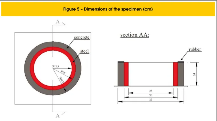
Grzybowski and Shah (1990) developed a test using a ring specimen to study the concrete cracking with restrained shrink
-age. The test consists in a concrete ring internally limited by a
steel ring, in which are placed strain-gages for strain
measur-ing, and an external microscope to measure the crack width. The tests proposed by the authors were conducted at ACBM laboratory (Center for Advanced Cement-Based Materials at Northwestern University, Evanston, Illinois) with the purpose to compare different types of shrinkage-reducing admixtures performances at early age. The dimensions of the specimens are given in figure 5.
The specimens were cured for 4 hours at 20oC and 100% RH, and
then after demoulding exposed to drying in the humidity room at
the ambient temperature of 20oC and 40% RH.
Figure 6 illustrates the test, the position of the strain-gages in the
steel rings and concrete ring prepared for testing.
To analysis the algorithm results, this paper studies two rings tested by Shah, Karaguler and Sarigaphuti (1993) and Shah et al
(1994). The results for temperature rising, moisture diffusion and stress development are presented. The comparison between the results for the time at which the cracks occur and the increase of the crack width is also showed.
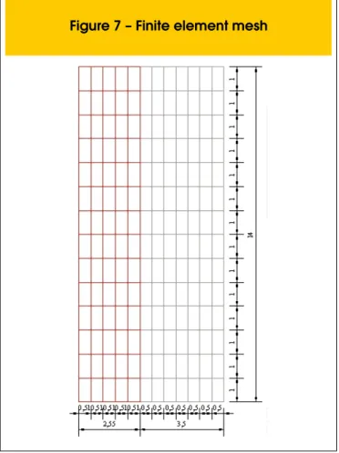
The mesh used for the inite element analysis has 168 elements and can be seen in igure 7.
The boundary conditions adopted for the axis-symmetrical analy
-sis (thermal, diffusion and mechanical) are shown in igures 8, 9
and 10.
mechanical analysis for both studied rings are shown in tables 3, 4 e 5.
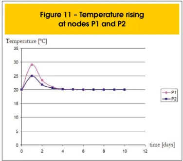
Figure 11 shows the temperature rising for two nodes, P1, situated in the central zone of the concrete ring, and P2, situated in the
external surface of the concrete ring.
The temperature development maps are shown in igure 12. It can
be seen that the maximum temperatures, due to the heat
gener-ated by the cement hydration reactions, occur in the central zone of the concrete ring. This situation was already veriied in igure 11, where the node P1, situated in the central zone of the concrete ring, reached a higher temperature than the node P2, situated in the external surface of the concrete ring. In the ifth day, the con
-crete ring temperature had already equalized with the environment
temperature.
Figure 13 shows the moisture diffusion development for two nodes, P1, situated in the central zone of the concrete ring, and P2, situ
-fusion development maps are shown in igure 14. It can be seen that the drying process, due to the environmental relative humidity is lesser than the initial relative humidity of the concrete ring, occur form the external surface to the central zone of the concrete ring. This situation was already veriied in igure 13.
The mechanical analysis results are shown for both rings tested, which properties were observed in table 5. The ring 2 (Shah, Kara
-guler and Sarigaphuti, 1993) were made with a concrete which compressive strength and Young modulus higher than ring 1 (Shah
et al, 1994).
Figure 15 shows, for ring 1 (Shah et al, 1994), the comparison
between experimental and numerical results for the time at which
the cracks occur and the increase of the crack width. Figure 16 shows the same comparisons for ring 2 (Shah, Karaguler and Sarigaphuti, 1993).
The stresses development maps for ring 1 (Shah et al, 1994) are
shown in igure 17. In these maps it could be observed that the crack opening occurs from the external surface to the interior of the concrete ring, to support what was observed in the test, according to igure 18.
The agreement between the numerical and experimental results, for the time at which the crack occurs and the increase of the crack width, is excellent. The numerical analysis shows why ring 2, with higher strength, cracks earlier than ring 1. The concrete shrinkage prescribed deformations generate stresses propor
-tional to Young modulus, and the tensile strength development at early age is not enough to avoid the cracking formation in the
stiffener ring.
It can be seen that, in the stresses development maps showed in figure 17, in the tenth day the red color appears in the ex
-ternal surface of the ring. This color corresponds to the stress level equivalent to the concrete tensile strength. So, the crack opens on the external surface, reducing the stress value. At the fourteenth day, the red stress level is reached again in
a further internal position (the stress on external surface is
close to zero). In sequence, with the crack propagation, the stress level falls down. At the nineteenth day, the stress peak is reached in a more internal position, being followed by the stress reducing. This circumstance successively repeats each
time closer to the steel ring surface.
8. Acknowledgments
This research project was supported by the Brazilian National Council for Scientiic and Technological Development (CNPq), by the Coordination of Improvement of Higher Education (CAPES), and by Center for Advanced Cement-Based Materials at North
-western University (ACBM).
9. References
[01] AURICH, M.. Simulação Computacional do
Comportamento do Concreto nas Primeiras Idades. Tese de Doutorado. Escola Politécnica da Universidade de São Paulo. 245p. 2008. [02] BALUCH, M. H., RAHMAN, M. K., MAHMOUD,
I. A.. Calculating drying-shrinkage stresses. Concrete International Magazine, july, pp. 37-41. 2008.
[03] BATHE, K. J.. Finite Element Procedures. Englewood Cliffs, New Jersey, Prentice Hall. (Edição revisada de Finite Element procedures in Engineering Analysis, 1982). 1996.
[04] BAZANT, Z. P., WU, S. T. Rate-type Creep Law of Aging Concrete based on Maxwell Chain. Materials and Structures, v. 7, n. 34, pp. 45-60. 1974.
[05] COMITÉ EURO-INTERNATIONAL DU BÉTON. CEB-FIP Model Code 1990. Lausanne, 1993. (Bulletin d´Information, 213/214).
[06] FÉDERATION INTERNATIONALE DU BÉTON. Structural Concrete. Textbook on Behavior, Design and Performance - Updated Knowledge of the CEB/ FIP Model Code 1990. 1999. (Bulletin 1-3).
[07] GRZYBOWSKI, M.; SHAH, S.P.. Shrinkage Cracking of Fiber Reinforced Concrete. Journal of the American Concrete Institute, v. 87, n. 2, pp. 138-148. 1990.
Speciication for Design and Construction of Concrete Structures. Japan Society Of Civil Engineers, Tokyo, Japan. 172p. 1999.
[09] JEON, S-J.. Advanced assessment of cracking due to heat of hydration and internal restraint. ACI Materials Journal, v.105, n. 4, pp. 325-333. 2008. [10] KWON, S. H., SHAH, S. P.. Prediction of Early
Age Cracking of Fiber-Reinforced Concrete due to Restrained Shrinkage. ACI Materials Journal, v.105, n. 4, pp. 381-389. 2008.
[11] LURA, P.. Autogenous deformation and internal curing of concrete. Tese de Doutorado.
Delft University of Technology. Delft. 2000. [12] MORABITO, P.. Methods to determine the heat of
hydration of concrete. Prevention of thermal cracking
in concrete at early ages. Report 15, R. Springenschmid, E & FN SPON. 1998. [13] OTTOSEN, N. S.. A failure criterion for concrete.
Journal of Engineering Mechanics Division, ASCE, 103, n. 4, p. 527-535, Aug. 1977.
[14] SHAH, S. P.; KARAGULER, M. E.; SARIGAPHUTI, M.. Effects of Shrinkage-Reducing Admixtures on Restrained Shrinkage Cracking f Concrete.
ACI Materials Journal, v. 89, n. 3, pp. 138-148, 1993. [15] SHAH, S. P.; OUYANG, C.; MARIKUNTE, S.; YANG,