The structural systems with wafle lat slabs are the most used in Brazil when the main requirement is lexible “layouts” and long spans with reason -able economy. However, few studies have been developed in Brazil regarding the behavior of these slabs when the lexural resistance is satisfac -tory and the shear in the ribs and punching resistances become competitive. This work shows the experimental analysis of 8 two-way reinforced concrete wafle lat slabs under centered load. The dimensions of the slabs were the same and equal to 1800 mm x 1800 mm x 140 mm. The ribs were 80 mm (height) by 50 mm (width) and the compressive concrete strength was approximately 40 MPa. The experimental results were compared to those estimated by the Brazilian code NBR 6118:2003. It was veriied that the resistance of the ribs is not satisfactorily estimated by the code, which excessively underestimates the results for ribs with and without shear reinforcement.
Keywords: reinforced concrete, wafle slab, lat slab, shearing, punching.
Os sistemas estruturais com lajes lisas nervuradas são os mais utilizados no Brasil quando a exigência principal é a disponibilidade de “layouts” lexíveis e grandes vãos com razoável economia. Entretanto, poucos estudos foram realizados no Brasil considerando o comportamento destas lajes quando a resistência à lexão é satisfatória e as resistências ao cisalhamento nas nervuras e ao puncionamento tornam-se concorrentes. Este trabalho traz as análises experimentais de 8 lajes lisas nervuradas bidirecionais de concreto armado sujeitas a carregamento centrado. As dimensões das lajes foram constantes e iguais a 1.800 mm x 1.800 mm x 140 mm. As nervuras apresentaram 80 mm de altura por 50 mm de base e a resistência do concreto à compressão foi de aproximadamente 40 MPa. Os resultados foram comparados aos estimados pela norma brasileira NBR 6118:2003 [1]. Veriicou-se que a resistência das nervuras não é satisfatoriamente estimada pela norma, subestimando demasia -damente os resultados para as nervuras sem e com armadura de cisalhamento.
Palavras-chave: concreto armado, laje nervurada, laje lisa, cisalhamento, punção.
Reinforced concrete wafle lat slabs under shearing
Lajes lisas nervuradas de concreto armado
ao cisalhamento
S. S. M. SOUZA a [email protected]
D. R. C. OLIVEIRA b
a Federal University of Para, PPGEC, [email protected], Augusto Correa Street, nº 01, district Guama, Belem, Para, Brazil. b Federal University of Para, PPGEC, [email protected], Augusto Correa Street, nº 01, district Guama, Belem, Para, Brazil.
Received: 28 Aug 2010 • Accepted: 17 May 2011 • Available Online: 07 Oct 2011
Abstract
1. Introduction
The increasing use of larger spans and the masonry walls directly on the slabs positing, mainly because of the architecture require -ments, are increasingly common on the loors of buildings. The massive use of lat slabs in such cases leads to higher thick -nesses, the structure may become uneconomic, as part of the bearing capacity of the slab is used to resist to its self weight. In this case, the use of ribbed lat slabs is an attractive alternative because it is a structural system that consists of slabs supported directly on the columns (without beam) through a massive region, and uni or bidirectional ribs, where part of the concrete below the neutral line is eliminated, being replaced by a illing mate -rial, which are commonly used blocks of expanded polystyrene (EPS), or removable formwork, reducing the weight of the slab and permitting larger spans.
The structural system in lat ribbed slabs has several advantag -es over the conventional solid slabs (beams and columns) in the same span, can cite the reduction in the formwork amount, the low -er consumption of mat-erials and manpow-er, and low-er self weight, creating a relief in the foundations, with or without inert material between the ribs. There is also greater freedom and lexibility to adapt the internal space (in the absence of beams) and is indicated primarily for residential buildings, hospitals and garages, ease the passage of common and special pipes lines.
Despite the advantages mentioned above, the elimination of the beams carries some disadvantages, such as increasing vertical displacements compared to conventional slabs with the same span, decreased overall stability of the structure due to horizontal actions, the possibility of failure by punching, consequently, pro -gressive collapse, and the possibility of shear failure of the ribs close to the solid concrete area. The failure by punching can occur due to concentrated loads or distributed in small areas, directly on the slabs. According to Souza and Cunha (1998) [2], this type of failure is so fragile and sudden (without warning), it usually occurs before the lexure reinforcement reaches the bending yield stress, which may cause progressive collapse of the structure. Thus, the objective of this study was to evaluate the behavior of 8 two-way lat slabs of reinforced concrete with shear reinforcement in the
ribs and punching reinforcement in the massive region, subjected to centered loads.
2. Experimental programm
2.1 Slabs characteristics
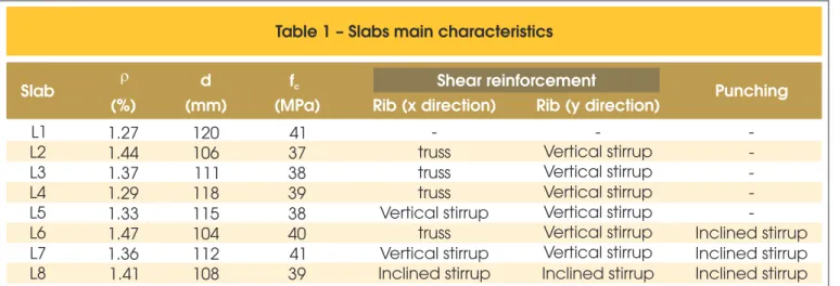
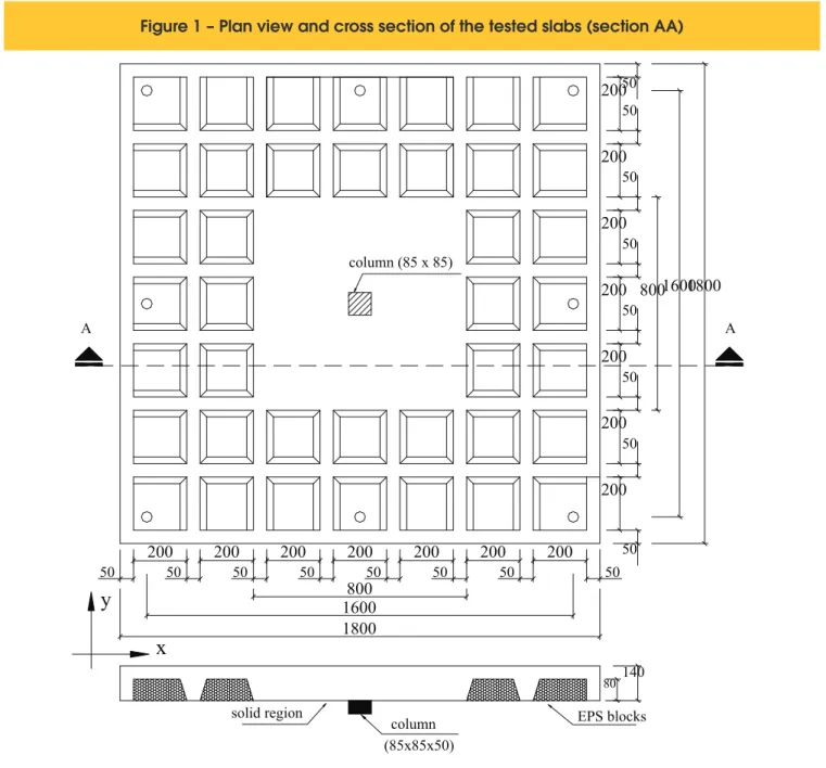
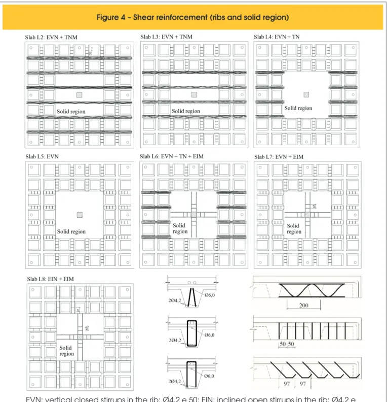
Tests were conducted in 8 two-way square ribbed lat slabs of rein -forced concrete with 1800 mm side and 140 mm thick. Loads were applied from the bottom of the slabs surface through a square metal plate with 85 mm side and 50 mm thick, simulating the ac -tion of a column. Reinforcement bending were the same for all slabs, consisting of bars of 6.0 mm and 12.5 mm diameter bars in the x direction and 12.5 mm in diameter in the y direction, pro -viding a geometric rate of reinforcement bending (r) of approxi -mately 1.40%, determined according to the recommendations of the CEB-FIP MC90 [3]. The main variables considered were the types of shear reinforcement in the ribs, consisting of trusses, verti -cal closed stirrups and open stirrups inclined at 45 degrees and the use of stirrups inclined at 45 degrees with punching reinforcement in the solid region. Table 1 shows the main characteristics and dimensions of the slabs are shown in Figure 1.
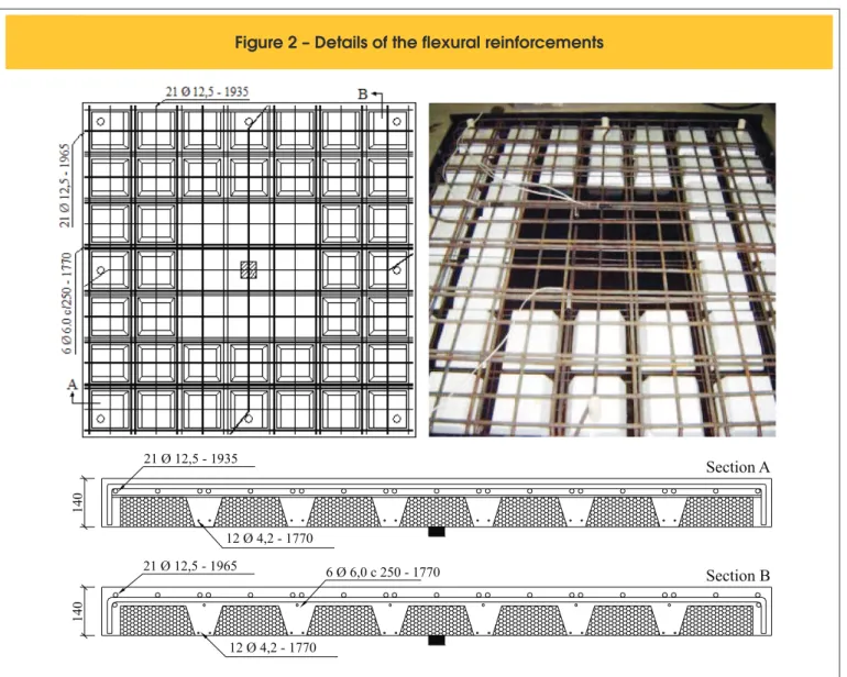
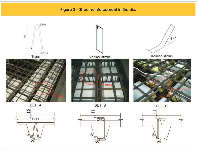
The main reinforcement, located on the upper surface of the slab, was composed of 21 bars of 12.5 mm and 6 bars of 6 mm in di -ameter in the x direction and bars 21 bars of 12.5 mm in di-ameter in the y direction. In the bottom surface of the slabs were placed only distribution reinforcement positioned longitudinally and trans -versely, composed of 12 bars of 4.2 mm in diameter in each direc -tion, and arranged two bars per rib. Figure 2 shows the positioning of the lexural reinforcement. For slabs with shear reinforcement in the ribs were used three different types of elements, consisting of trusses (TR 8644), in order to investigate the eficiency of the diagonals in the shear resistance, vertical closed stirrups and open stirrups inclined of 45 degrees, and all the stirrups were made of 4.2 mm in diameter. Figure 3 shows the three types of reinforce -ment used.
Regarding the punching reinforcement in the solid area were used open stirrups inclined of 45 degrees, from bars with a diameter of 6.3 mm and arranged in three layers distributed in cross. The
Table 1 – Slabs main characteristics
Slab
r
d
fc
Shear reinforcement
(%)
(mm)
(MPa)
Rib (x direction)
Rib (y direction)
Punching
L1
1.27
120
41
-
-
-
L2
1.44
106
37
truss
Vertical stirrup
-
L3
1.37
111
38
truss
Vertical stirrup
-
L4
1.29
118
39
truss
Vertical stirrup
-
L5
1.33
115
38
Vertical stirrup
Vertical stirrup
-
L6
1.47
104
40
truss
Vertical stirrup
Inclined stirrup
L7
1.36
112
41
Vertical stirrup
Vertical stirrup
Inclined stirrup
L8
1.41
108
39
Inclined stirrup
Inclined stirrup
Inclined stirrup
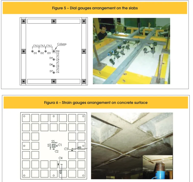
surface of the slabs. Figure 5 shows the scheme of the gauges positioning on the slabs, indicated by the letter D.
2.2.2 Concrete Surface
To measure the concrete strains were used strain gauges (EERs) ixed to the bottom surface of all slabs, and subsequently connect -ed to the equipment data acquisition (Spider 8). Four EERs were used (C1, C2, C3 and C4) on the slab without shear reinforcement (L1) and on the slabs where the shear reinforcement was different in the x and y directions (L2, L3, L4 and L6), whereas in slabs with the same shear reinforcement in both directions (L5, L7, L8) were ixed only two EERs (C1 and C3).
choice for this type of shear reinforcement was due to the ease of installing them on the slab, but also outperforms the vertical stir -rups, considering the ultimate resistance of the elements, accord -ing to Oliveira (1998) [4]. Figure 4 shows the placement of shear reinforcement in the ribs and in the solid area.
2.2 Slabs monitoring
2.2.1 Displacements
The vertical displacements were measured using 7 dial gauges
positioned in the middle of the span, distributed in two directions (x and y), spaced 174.5 mm apart and in contact with the upper
Figure 1 – Plan view and cross section of the tested slabs (section AA)
50
200
50200
50200
50200
50200
50200
50200
50800
1600
1800
50
1800
column (85 x 85)200
800
1600
2.2.4 Shear Reinforcement
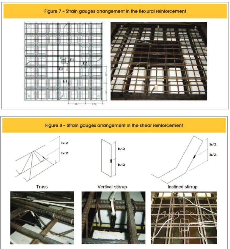
To measure the shear reinforcement strains in the ribs and solid area were set EERs of the same type used in the lexural reinforcement. In shear reinforcements composed of trusses was placed a strain gauge on the tensile diagonal and in the shear reinforcement composed of stirrups, both vertical closed and open inclined at 45 degrees was set a strain gauge on a leg of the stirrup, positioned at half height (Figure 8).
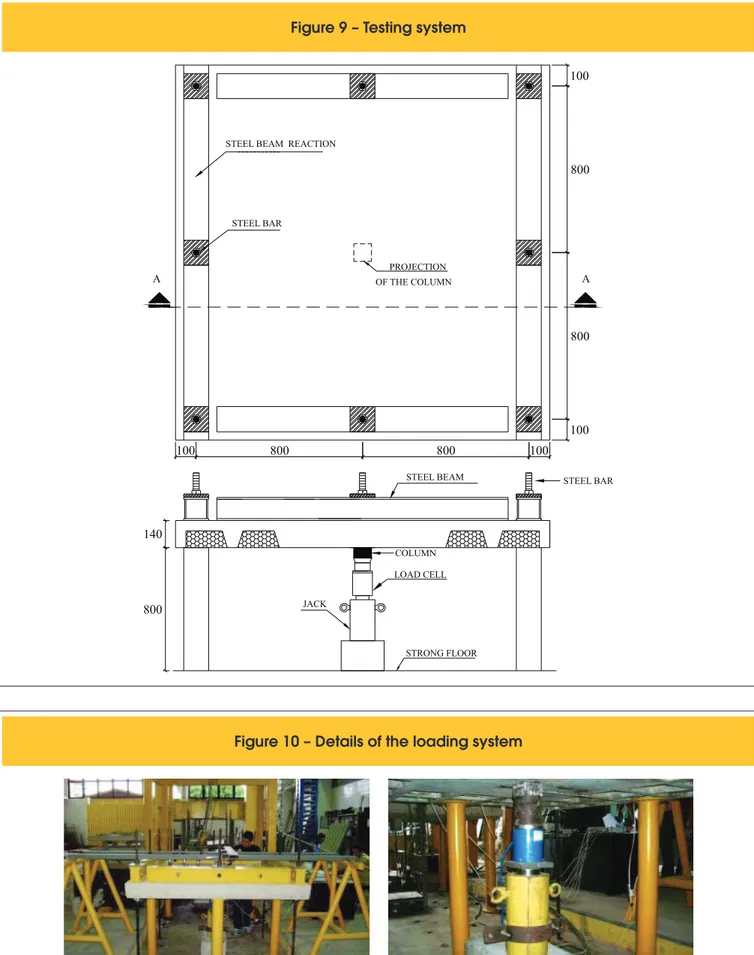
2.3 Loading system
The test system consisted of slabs supported on all four sides by
steel beams reaction, simulating a continuous support of the slabs. The load was applied through a hydraulic cylinder on a steell plate simulating the action of a column, powered by a hydraulic pump whose intensity was measured by a load cell coupled to a digital display. The loading applied to the tested slabs was transmitted to the laboratory slab by reaction of 8 steel ties.
After the assembly process of the system, the loading was applied
upward from the slabs bottom surface, adopting a load increase of The EERs were positioned in the region 55 mm away from the face of
the column, and only in the tangential direction, this position is justiied by the fact of having a predominance of tangential stresses on the radial stresses in this type of structural system (Oliveira, 1998). The position -ing of the strain gauges in the concrete surface is shown in Figure 6.
2.2.3 Flexural reinforcement
The lexural reinforcement strains were monitored in the same way that those on the concrete surface, taking into account the type of shear reinforcement ribs in the x and y directions, but always in the direction of the tangential stresses of the slabs as well as the tangential strains are much more important than the radial. Each bar was instrumented using one strain gauge at half height of the bar. The slabs L1, L2, L3, L4 and L6 showed the same position and amount of strain (E1, E2, E3 and E4) and similarly the slabs L5, L7 and L8 showed the same position and amount of strain gauges (E1 and E3). Figure 7 shows the positioning of the strain gauges in the lexural reinforcement and a detail of the gauges installation on the bars surfaces.
21 Ø 12,5 - 1935
12 Ø 4,2 - 1770
Section A
21 Ø 12,5 - 1965
12 Ø 4,2 - 1770
6 Ø 6,0 c 250 - 1770
Section B
140
140
approximately 10% of the estimated failure load. For each load incre -ment the vertical displace-ments were measured through seven dial gauges and readings of the strains in reinforcement and concrete were performed with two modules of the equipment data acquisition Spider 8. The details of the test system are shown in Figures 9 and 10.
3. Results
3.1 Materials
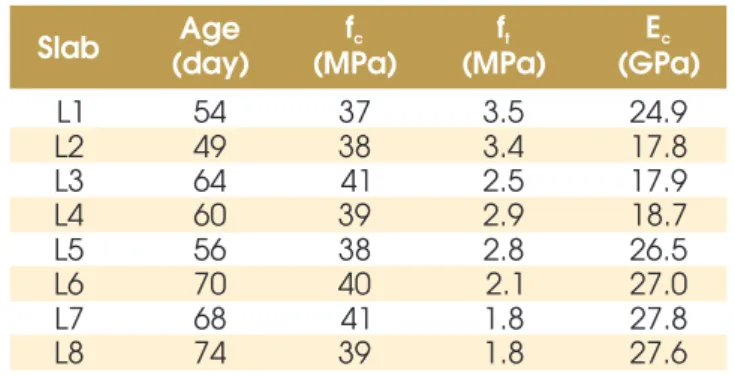
The mechanical properties of concrete were determined from tests of compressive strength, tensile strength by diametrical compres -sion and modulus of elasticity, according to NBR 5739:1994 [5], NBR 7227:1994 [6] and NBR 8522:1984 [7], respectively. The re -sults presented in Table 2 represent the average of the three proof cylinders tested for each slab in their ages. The characteristics of the steels used in this study were obtained from axial tensile test, according to NBR 6152:1992 [8] and are presented in Table 3.
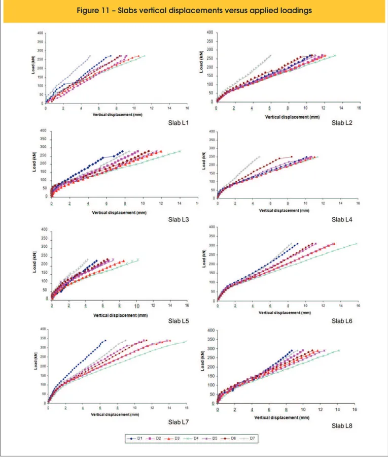
3.2 Displacements
The dial gauges were distributed in two directions (x and y) in order
to compare the behavior of the slabs due to the variation of shear reinforcement in the ribs and the use of punching reinforcement. Figure 11 shows the vertical displacements observed in the slabs. Figure 12 shows the vertical central displacements (D4) of all slabs for each load applied. The vertical displacements of the slabs were different for the corresponding points in both directions, indicating possible problems of symmetry of the column or support, and even the occurrence of differential accommodation of the test system during the tests. The greatest discrepancies were found in L4 slab for the meters D1, D2, D6 and D7. But the central gauge (D4), placed on loaded region, had the highest vertical displacements for all slabs, as expected. The maximum displacement (Figure 12) shows a similar behavior between the slabs, with three slabs with punching reinforcement (L6, L7 and L8) showed the largest inal displacements.
3.3 Concrete strains
Only the tangential strains were measured, once they are high -er than the radial ones (Oliveira, 1998 and Smith, 2004 [9]). The slabs L6 and L7 were the ones with the largest strains (4.19 ‰ and 3.64 ‰, respectively), indicating the occurrence of t concrete
crushing in these slabs. Figure 13 shows the maximum strains of the concrete for all slabs.
3.4 Flexural reinforcment strains
The largest strains were recorded near the column (E1) in the
slab L7, with the flexural reinforcement showing maximum strain of 4.38 ‰, reaching the yielding (strains greater than 2.5 ‰). In addition L7 slab, the flexural reinforcements of the slabs L1 (3.76 ‰), L2 (2.72 ‰) and L6 (3.79 ‰) also yielded. Figure 14 shows the maximum strain in the flexural reinforce
-ment of the slabs.
EVN: vertical closed stirrups in the rib: Ø4.2 e 50; EIN: inclined open stirrups in the rib: Ø4.2 e
97; EIM: inclined open stirrups in the solid region: Ø6.3 e 65; TN: truss in the rib: Ø4.2 e 200;
TNM: truss in the rib and solid region: Ø4.2 e 200.
3.5 Shear reinforcement strains
The strains in ribs shear reinforcement were much smaller than the yield strain of steel (εysw=4.7 ). However, in some slabs (L6 and L7), there was a change in the shear failure mode of the ribs for lexure, being the effective the inclined reinforcement (truss and open stirrups inclined at 45 degrees) for slabs providing greater ductility. Figure 15 shows the strains of the shear reinforcement in two of the slabs tested. In relation to punching reinforcement (45 degrees inclined stirrup), despite having been requested enough, had no stirrup yielding (strain greater than 4.43 ‰), and reached the maximum deformation of 3.34 ‰, observed in the slab L8 (the
slab with inclined stirrups in the ribs), i.e. performed better when coupled with the use of inclined stirrups in the ribs. It can be seen (Figure 16) that with approximately 80% of tensile strength, the reinforcements began to strain in a non linear manner in relation to the applied loads, indicating that the yielding was not so far and conirming the gain of ductility of the slabs obtained with the intro -duction of shear reinforcement.
3.6 Loads and failure modes
The use of shear reinforcement in the ribs did not cause gains in ul
-timate load, because sometimes the lexural or punching strength
Figure 5 – Dial gauges arrangement on the slabs
D1 D2 D3 D5
D6
D7 D4 174,5 174,5 174,5
174,
5
174,
5
174,
5
Column
Figure 7 – Strain gauges arrangement in the flexural reinforcement
Figure 8 – Strain gauges arrangement in the shear reinforcement
had been reached, making it impossible for the shear reinforce -ment were requested in order to provide an increase in the failure loads. In relation to punching reinforcements, they provide signii -cant gains for failure load, compared to the reference slab (L1), giving to the slabs, with this kind of reinforcement, a more ductile behavior. Table 4 shows the loads and modes of failure observed in the slabs. In situations where it was not possible to clearly observe
the failure mode, the criterion used for classiication was based on that presented by Oliveira (1998) [4], where the lexure mode oc
-curs for Pu/Plexure > 1.0, with strains on the lexural reinforcement
Figure 9 – Testing system
A A
800
800
100 100
800 800 100
100
STEEL BEAM REACTION
STEEL BAR
PROJECTION
140
800 JACK
LOAD CELL COLUMN
STEEL BEAM
STRONG FLOOR OF THE COLUMN
STEEL BAR
Table 2 – Concrete mechanical properties
Slab
Age
f
cf
tE
c(day)
(MPa)
(MPa)
(GPa)
L1
54
37
3.5
24.9
L2
49
38
3.4
17.8
L3
64
41
2.5
17.9
L4
60
39
2.9
18.7
L5
56
38
2.8
26.5
L6
70
40
2.1
27.0
L7
68
41
1.8
27.8
L8
74
39
1.8
27.6
f :tensile strength of concrete; t
E : modulus of elasticity of concrete.c
Table 3 – Steels mechanical properties
f
f
ysf
ue
ysE
s(mm)
(MPa)
(MPa)
(‰)
(GPa)
4.2
630
705
4.7
233
6.0
590
688
4.5
236
6.3
588
794
4.4
242
12.5
601
740
2.5
255
f: bars diameter;
f and f : yield and failure strength, respectively;ys u
eys: yield strain;
E : longitudinal modulus of elasticity.s
slabs L6 and L7 were classiied as lexure, followed by punching (punching cone formation). The remaining slabs failure by punch -ing, characterized by a sudden and brittle failure. Figure 17 shows the failure surface of the slabs and Figure 18 shows the cracking pattern of the slabs at the end of the tests.
3.7 Comparisons between experimental
and estimates results
Table 5 presents the estimated failure loads according to NBR 6118:2003 for punching and shear in the ribs, and lexural resis -tance from yield line theory using the equations developed by Oliveira (2003) [10], and the experimental failure loads. In general, the normative estimates for shear strength of ribbed slabs were conservatives, including those with shear reinforcement in the ribs, showing that the security of the slabs would be even greater if the failures were in the ribs.
Regarding the punching resistance, the estimates from NBR 6118:2003, showed that this code tends to overestimate the results, and in some cases considered satisfactory, although not always coincide with the observed failure mode, but also provided some conservative results. For the lexural strength can be observed that with the exception of L6 slab, all slabs had higher estimates to the experimental results. In the slabs without punching reinforcement
the resistance was overestimated, on average, 23%, indicating that a lexural failure was far, with the slabs L1 and L2 presenting punching failures. The slabs with punching reinforcement L6 and L7 showed estimated resistances close to the experimental ones and were satisfactory even for the observed failure modes.
4. Conclusions
The slabs with shear reinforcement in the ribs (L2, L3, L4 and L5)
did not achieve signiicant resistance in relation to the reference slab (L1). In relation to the slabs with punching reinforcement (L6, L7 and L8), they showed superior resistance to the slab L1, around 26%, conirming the eficiency of the inclined stirrups as punching reinforcement.
Considering the slab (L1) the ultimate strength was too underesti
-mated for a failure in the ribs. The other slabs also had estimates well below the experimental results. For the slabs with shear and punching reinforcements (L6, L7 and L8) the disparity was much greater, resulting in estimated failure loads of approximately 2 times smaller than the experimental ones, since the contribution of the punching reinforcement is not considered in this design. In to the punching failure loads estimates, most of the results were satisfactory, with differences between the experimental results up to 5%. It must be observed the not ever a punching failure was observed, even for slabs in which the results were considered satisfactory.
5. Acknowledgements
The authors thank CNPq, CAPES, FADESP, ITEGAM and FAPESP for inancial support for this work.
6 References
[01] Association of Technical Standards, NBR 6118 - Design of Concrete Structures. Rio de Janeiro, 2003. [02] Souza, V. C. M., CUNHA, A. J. P. Prestressed and
Reinforced Concrete Slabs. Rio de Janeiro, Ed UERJ, 1998, 580p.
[03] CEB - FIP (1990). Model Code 1990: Final Draft. Bulletin d’Information, No 203-205, CEB, Lausanne, July 1991.
[04] OLIVEIRA, D. R. C., Experimental Analysis of Reinforced Concrete Flat Slabs with Punching Reinforcement. Department of Civil and Environmental Engineering, University of Brasilia, Master Thesis, Brasília, 1998, 137p.
[05] BRAZILIAN ASSOCIATION OF TECHNICAL STANDARDS. NBR 5739 - Testing of compression in cylindrical concrete proof bodies. Rio de Janeiro,1994. [06] BRAZILIAN ASSOCIATION OF TECHNICAL
STANDARDS. NBR 7222 - Mortar and Concrete - Determination of tensile strength by diametrical compression of cylindrical proof bodies - Test Method. Rio de Janeiro, 1994.
Figure 12 – Slabs middle span vertical
displacements (D4)
Figure 13 – Slabs concrete strains
Figure 14 – Slabs flexural reinforcement strains
[08] BRAZILIAN ASSOCIATION OF TECHNICAL STANDARDS. NBR 6152 - Metallic materials. Determination of Mechanical Properties Tensile - Test Method. Rio de Janeiro, 1992.
[09] Soares, Y. V. Experimental Analysis of Reinforced Concrete Ribbed Flat Slabs with Metallic Columns. Department of Civil and Environmental Engineering,
University of Brasilia, Master Thesis, Brasília, 2004, 200p.
Figure 15 – Slabs L2 and L5 shear reinforcement in the ribs strains
L2 L5
Figure 16 – Slabs L6 and L8 shear reinforcement in the solid region strains
L6 L8
Table 4 – Slabs loads and modes of failure
Slab
d
r
f
ce
s, maxe
c, maxShear reinforcement
P
uFailure
mode
(mm)
(MPa) (‰)
(‰)
Rib
Punching
(kN)
L1
120
0.0127
41
3.8
3.1
-
-
280.0
punch
L2
106
0.0144
37
2.7
2.9
Truss
-
278.5
punch
L3
111
0.0137
38
2.2
2.8
Truss
-
287.5
punch
L4
118
0.0129
39
2.3
2.8
Truss
-
287.0
punch
L5
115
0.0133
38
2.8
2.5
Vertical stirrup
-
235.0
punch
L6
104
0.0147
40
3.8
4.2
Truss
Inclined stirrup
380.0
flexure
L7
112
0.0136
41
4.4
3.6
Vertical stirrup
Inclined stirrup
361.0
flexure
L8
108
0.0141
39
2.2
-
Inclined stirrup Inclined stirrup
322.0
punch
es, max: maximum observed tensile strain for flexural reinforcement;
ec, max: maximum observed compressive strain for bottom concrete surface;