Behavior of reinforced concrete columns strenghtened
by partial jacketing
Estudo do comportamento de pilares de concreto
armado reforçados pela técnica do encamisamento
parcial e uso de conectores
a Federal University of Goiás, School of Civil Engineering, Goiânia, GO, Brazil;
b Pontifícia Universidade Católica de Goiás, Department of Civil Engineering, Goiânia, GO, Brazil.
Abstract
Resumo
This article presents the study of reinforced concrete columns strengthened using a partial jacket consisting of a 35mm self-compacting concrete layer added to its most compressed face and tested in combined compression and uniaxial bending until rupture. Wedge bolt connectors were used to increase bond at the interface between the two concrete layers of diferent ages. Seven 2000 mm long columns were tested. Two columns were cast monolithically and named PO (original column) e PR (reference column). The other ive columns were strengthened using a new 35 mm thick self-compacting concrete layer attached to the column face subjected to highest compressive stresses. Column PO had a 120mm by 250 mm rect-angular cross section and other columns had a 155 mm by 250mm cross section after the strengthening procedure. Results show that the ultimate resistance of the strengthened columns was more than three times the ultimate resistance of the original column PO, indicating the efectiveness of the strengthening procedure. Detachment of the new concrete layer with concrete crushing and steel yielding occurred in the strengthened columns.
Keywords: columns, strengthening, concrete, bolts.
Este artigo apresenta um estudo do comportamento de pilares de concreto armado reforçados por encamisamento parcial, com o uso de uma ca-mada de 35 mm de concreto auto adensável na face mais comprimida submetidos à lexo-compressão até à ruptura. Foram utilizados parafusos conectores como armadura de ligação entre as duas camadas de concreto de diferentes idades. Foram ensaiados 7 pilares de 2000 mm de altu -ra, sendo 2 peças concretadas monoliticamente nomeadas de PO (pilar original) e PR (pilar de referência). Os outros 5 pilares foram reforçados utilizando uma camada de 35 mm de concreto moldada na face submetida a maior compressão. O pilar PO tinha uma seção transversal retangu -lar de 120x 250 mm e as demais colunas 155 x 250 mm após executado o reforço. Os resultados alcançados mostram que os pi-lares reforçados atingiram uma resistência de aproximadamente três vezes maior com relação ao pilar PO, demostrando eiciência da técnica utilizada. Os pilares apresentaram o desplacamento da camada de reforço nas cargas inais, com tendências ao esmagamento do concreto e escoamento do aço.
Palavras-chave: pilares, reforço, concreto, parafusos.
D. B. FERREIRA a
R. B. GOMES a
A. L. CARVALHO b
G. N. GUIMARÃES a
1. Introduction
Diferent types of pathologies can appear in structures which can cause a large number of problems and can ultimately lead to failure. Among these problems are design and execution laws, use of low quality materials and changes in building use. A com-mon strengthening technique for reinforced concrete structures consists of jacketing the member by adding new concrete to its sides increasing the size and resistance of the cross sec -tion. For a column strengthened using jacketing it is important to guarantee stress transfer at the new concrete/ old concrete interface. According to Gomes & Appleton [1], this technique is usually more adequate when the need occurs to increase com-pressive strength, increase the size of the cross section or to add more steel reinforcement to the concrete cross section. It is necessary to avoid detachment of the new strengthening con-crete added to a column member, when it is again at service loads, for the jacketing technique to work.
This article presents a study on the experimental behavior of seven reinforced concrete columns subjected to compression and uni-axial bending and strengthened by adding a self-compacting con-crete layer to its most compressed face. This technique is frequent-ly used in local construction. Sleeve wedge bolt connectors were used to increase bond at the old concrete-new concrete interface. The objective of this research is to analyze column behavior with respect to ultimate loading and the eiciency of the interaction of
of connectors.
2. Previous research
Research on columns has been done to obtain design pa-rameters for use in column design present in codes. Among such research, the study done by Ibrahim e MacGregor [2] analyzed the results obtained on tests of 20 columns (both reinforced and unreinforced) where high strength reinforced concrete was used. Much of the test setup used in this re-search was similar to the one used by Ibrahim e MacGregor [2]. Results show that the concrete cover of reinforced con-crete columns detached at an average concon-crete strain be-tween 4.0‰ and 4.5‰ for columns with a rectangular cross section, and between 4.7‰ and 5.2‰ for columns with a tri -angular cross section.
Adorno [3] started a series of studies done with the University of Brasilia (UnB) and the Federal University of Goias on re -inforced concrete columns subjected to uniaxial bending and compression. Column dimensions and details of column steel reinforcement are shown in Figures 1 and 2 for the model column used in the study. Several researchers (Araújo [4], Omar [5], Sahb [6] e Nascimento [7]), at those two univer -sities, followed Adorno’s line of research. Except for Araujo [4], they followed through with studies on column strengthen -ing us-ing a concrete jacket-ing with self-compact-ing concrete (SCC) and different kinds of connectors at the new concrete-old concrete interface were used.
Omar [5] researched column jacketing on different column faces using a layer of self-compacting concrete (SCC). The original columns were loaded until longitudinal steel yielding and then unloaded and strengthened with a concrete jacket. A new concrete layer was added to different column faces (com-pressive face, tension face and both faces). Stirrup shaped connectors (Φ 5 mm bar diameter) and additional longitudinal steel were used in the new concrete layer.
Following Omar’s research, Sahb [6] used wedge bolts as connectors between the two concrete layers of different ages in the jacketing procedure. Columns were reinforced on the most compressed side only with additional longitudinal rein-forcement for shrinkage. The objective of the study was to minimize detachment of the new concrete layer and avoid a fragile mode of failure.
Open stirrups attached to the original column stirrups were used as connectors between the old substrate concrete and the new strengthening concrete in the work done by Nasci-mento [7]. The original column stirrups had to be exposed to anchor the new connector.
All columns tested by these researchers presented good re-sults with increases in column ultimate capacity ranging from two to close to four times the resistance of the column without jacketing. However, a fragile mode of failure with detachment of the strengthening concrete layer occurred in almost all cas-es. Only one column tested by Nascimento [7] obtained a duc -tile mode of failure (without concrete cover detachment) and an increase in ultimate load capacity. New research is needed to minimize concrete detachment and obtain ductile failure.
Figure 1 – Column dimensions in mm
(ADORNO [4])
500
250 View B-B
250 120
View A-A 500
2000
120 100 280
3. Experimental program
Development of this research was based on previous work done by Adorno [4] and Sahb [6]. The columns tested and the test setup had the same basic properties as their work, such as: concrete cross section, steel reinforcement, connector type, type of con-crete and casting procedure.
Seven rectangular columns were tested subjected to compression and one-axis bending with and initial load eccentricity of 60mm. Five of the seven columns were strengthened at the most com -pressed face with the addition of a concrete layer (jacket) and use of wedge bolts along its length to increase adhesion between the old concrete substrate and the new concrete layer.
Column nominated as PO corresponds to the original column with-out strengthening with the rectangular cross section of 120 mm by 250 mm. Five strengthened columns were originally cast with a 120mm by 250mm cross section and the jacket consisted of a 35 mm layer of self-compacting concrete was later added to the compression face. Therefore, the ive strengthened columns had a 155 mm by 250 mm cross section when tested and all were strengthened with sleeve wedge bolts placed perpendicular to
the concrete interface formed after adding the new concrete 35 mm layer. Connectors are shown in Figure 3 and were manually ixed to the column so that 15mm of the connector was inside the
Figure 2 – Steel reinforcement details (ADORNO [4])
A A B B N2 N3 N1 N5 N6 N7 N8
4 N1 -10 L
T = 1950mm N6
2x11 N3
5 c. 50 LT= 640 mm
70
200 50
2x11 N4
5 c. 50 LT= 650 mm 50
70 440
500
140
2x4 N5
10 LT= 1080 mm View B-B
N1
N3 N1
N5 N4
9 N2
5 c. 100 LT= 640 mm
70
200 50
View A-A N1
N2
2x4 N6
5 LT= 550 mm
70 50 280200
200
2x3 N7
5 LT= 1400 mm
450
200 50
2x7 N8
5 LT= 800 mm
200
150 50
a 155 mm by 250 mm cross section and has the same cross section as the strengthened columns but was cast monolithi-cally. Since column PR was cast monolithically it should corre -spond to the strengthened column at its best as far as column load capacity is concerned. Column length was 2000 mm. The specimens were built with two corbels, one at the base and another at the top of the column, to avoid stress concentrations due to load application and to allow application of a vertical force with an eccentricity that will provide bending moment at the column mid-height so that the column will be under com-pression and uniaxial bending.
Two casts were made using self-compacting concrete. Columns with the original dimensions and the reference column were cast irst, and the strengthening layer was added in a second cast. Speciic testing on the fresh self-compacting concrete was done according to NBR 15823-1, namely: slump test, V-funnel test and L-Box test, using the equipment shown in Figure 4.
Testing was divided in two series. The irst one tested four col
-strengthened columns nominated P150-18 e P150-26 with con-nectors spaced vertically every 150 mm following the same geometrical properties as Sahb’s [6] research. Column P150-18 had a total of 18 connectors and P150-26 had a total of 26 con-nectors. Three columns with connectors spaced vertically every 100 mm were tested as the second series and they were nomi-nated as P100-26, P100-38 e P100-50 and they had a total of 26, 38 and 50 connectors, respectively. Figure 5 shows connec -tor positioning for all columns.
During testing of column P100-26, a problem occurred with the hydraulic jack and testing was interrupted. Therefore, testing for column P100-26 was divided in two parts and the irst part was renamed as P100-26a. After ixing the jack, reloading of the col -umn was done and testing proceeded until rupture. This second part of the test was renamed as P100-26b and only a ruler and displacement indicator R3 were used as instrumentation. Procedure for column jacketing were as follows: identiication of original stirrup positions, identiication for connector positioning, hole execution, old concrete scariication, connector placement, cleaning , concrete surface saturation and casting of new con-crete layer (jacket).
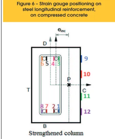
Electrical resistance strain gauges positioned along the steel reinforcement and on the concrete surface at column mid-height were used to measure strains on the steel and concrete surface as shown in Figure 6.
Horizontal and vertical displacements were measured by digital displacement indicators as shown in Figure 7. These indicators had a 0.01 mm precision and a 50 mm gauge length. Indica-tor installation procedure consisted on mounting a ixed device on a vertical support placed behind the column and the indica-tor cursor was placed on small metal plates glued to the col-umn’s surface. Indicators were removed prior to rupture to avoid equipment damage. A complementary reading of mid-height displacement (same height as digital indicator R3 was placed) was taken using a standard measuring tape and it was used to measure horizontal mid-height displacements after removal of the digital indicators.
Figure 8 presents the test setup which is basically the column attached to a steel frame on a reaction slab. The columns were transported to the reaction steel frame using an overhead bridge crane. They were positioned on the reaction frame with the help of a 300 kN hydraulic jack which was used to help position the setup’s steel plates and lock the column into place with the as-sembly steel beams.
Vertical load application was done using a hydraulic jack with a 300 kN capacity attached to a manual hydraulic pump. The hy-draulic jack was placed under the column on the reaction slab. A 300 kN capacity load cell was placed at the column’s top. All strains and load cell readings are recorded digitally on a mi-crocomputer. Some of the testing equipment was removed just prior to failure to avoid damage.
4. Test results
4.1 Displacements
Maximum displacements were measured by digital indicator R3
Figure 4 – Tests on fresh SCC
Slump test V-funnel
A
B
positioned at column mid-height and results are shown in Figure 9 for all columns. The dotted vertical line refers to Brazilian Con -crete Code NBR 6118 [8] displacement limit of L/250 for bars in lexure at service limit state conditions, which was used in this study only as a comparison parameter.
The highest measured displacement occurred for the original column PO and measured 26 mm, followed by displacements for reference column PR. Column P150-26 with 26 connectors showed highest displacements for the strengthened columns. All strengthened columns showed displacement curves with larger slopes than original column PO indicating the jacketing technique reduces column displacements since the size of the cross section increases. Column PR had the same dimensions
as the strengthened columns and displacement curves had sim-ilar slopes.
Strengthened columns were more rigid as the number of con -nectors increased. The displacement curve for column P100-50 with the greatest number of connectors is closest to the dis-placement curve for reference column PR.
4.2 Steel strains
initial loading, except for column P150-18 which shows a small level of compression at initial loads. Only the steel in column PO showed strains above the yielding, indicate by the dotted vertical line. Since some of the recording equipment was removed before failure (at about 80% of ultimate load), it may be possible that lon-gitudinal steel may have yielded in other columns as well, espe-cially columns P100-26 and P150-26 which show latter curves at
higher loads. Steel strains in strengthened columns were smaller than those strains in the original column PO and higher than refer-ence column PR.
In general, strengthened column stifnesses increased with an in -crease in the number of connectors. The strengthened columns, with the exception of column P150-18, had higher steel strains than those obtained in the reference column PR and smaller that those obtained in original column PO.
Figure 11 shows load vs strain curves for strain gauges placed on the compression steel reinforcement at column mid-height. Col-umn PR showed greatest compressive strains. With the exception of column P100-26, all strengthened columns show a change in slope near the end of the test with a reduction in the compression strains indicating a sharp movement of the neutral axis of the cross section. However, this did not occur in columns PO and PR.
4.3 Concrete strains
For analysis of concrete strains, only the results from the strain gauges with the largest strains were considered. Figure 12 shows
load vs concrete strains for all columns. The two vertical dotted lines in Figure 12 indicate the ultimate concrete strains speciied in ACI Code 318 [9] and in Brazilian Code NBR 6118 [8] at 3.0 mm/m and at 3.5 mm/m, respectively.
Concrete strains in strengthened columns, except for column P150-18, reached the ACI Code ultimate strain. Although monolithically cast columns PO and PR and strengthened column P150-18 did not reach the Code’s ultimate strain, their behavior was similar to the other columns which is shown by almost lat, horizontal curves near ultimate loading. No column strains were above the ultimate concrete strain established by the Brazilian Code and strains in column P150-26 were closest to its ultimate concrete strain value. All columns showed compressive strains since the start of loading. Again, the slope of the curves is related to the number of con-nectors. An increase in the number of connectors indicates higher stifness for the strengthened columns, except for column P150-18 which behaved similar to column P100-50. Strains for column P100-26 are smaller than other columns, except the original col-umn PO, which can be explain by the fact that the test had to be interrupted and the column reloaded with some cracking already
Figure 10 – Load vs tension steel strain curves
Figure 11 – Load vs compressed steel
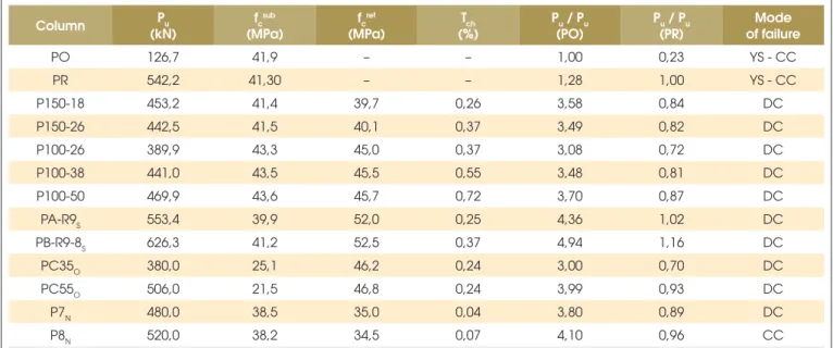
columns PO and PR were taken as parameters for comparisons. The additional parameter is connector ratio Tch which is deined as the ratio between the total cross sectional area of all connectors in a column and the area of the new concrete/old concrete interface. Table 1 shows ultimate loads, modes of failures, material proper-ties of the concrete substrate and the concrete used for jacketing, connector ratio Tch, and ratios between ultimate loads. The table also presents data from previous studies done by Omar [5], Sahb [6] e Nascimento [7] which analyzed similar columns.
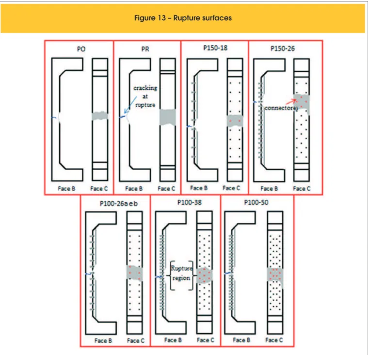
Rupture in all columns occurred at the column’s mid-height re-gion as shown in Figure 13. Only column P150-26 had concrete ruptured slightly above the column mid-height. Figure 14 shows
photographs of these ruptures for several columns. None of the connectors failed.
Ultimate load capacity increased of strengthened columns and ulti-mate loads ranged from 3.1 to 3.7 times the ultiulti-mate load capacity for original column PO. This strength gain was in direct proportion to the number of connectors for each column, with the exception of column P150-18. Column P150-18 has a low connector ratio of 0.25% but its ultimate load capacity was smaller than only two columns: P100-50 and PR.
Columns P150-18 and P150-26 had smaller ultimate loads than columns PA-R9S e PB-R9-8S tested by Sahb [6] which had the same number of connectors and distribution scheme. This difer -ence can be attributed to diferent concrete compressive strengths of jacket as shown in the third column of Table 1.
Omar‘s [5] column PC35 had an ultimate load close to strength-ened column P100-26 with a higher connector ratio. Columns tested by Nascimento [7], with smaller reinforcing ratios and lower concrete strengths, had ultimate loads four times higher than origi-nal column PO. This can be explained by use of diferent wedge bolt installation techniques, not to mention that Nascimento’s col-umn P8N was the only one in these studies that did not have the concrete jacket detached but showed concrete crushing.
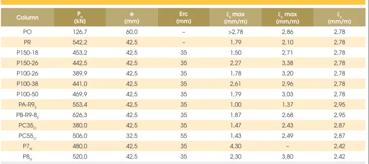
Table 2 shows results obtain from researchers mentioned above such as column eccentricity, thickness of the strengthening layer, maximum strains and steel yield strains.
5. Conclusions
Five reinforced concrete columns strengthened using a partial jacket consisting of a 35mm self-compacting concrete layer added to its most compressed face were tested in combined compression and uniaxial bending until rupture. Wedge bolt connectors were used to increase bond at the interface between the two concrete
Column Pu
(kN)
fcsub
(MPa)
fcref
(MPa)
Tch (%)
Pu / Pu (PO)
Pu / Pu (PR)
Mode of failure
PO 126,7 41,9 – – 1,00 0,23 YS - CC
PR 542,2 41,30 – – 1,28 1,00 YS - CC
P150-18 453,2 41,4 39,7 0,26 3,58 0,84 DC
P150-26 442,5 41,5 40,1 0,37 3,49 0,82 DC
P100-26 389,9 43,3 45,0 0,37 3,08 0,72 DC
P100-38 441,0 43,5 45,5 0,55 3,48 0,81 DC
P100-50 469,9 43,6 45,7 0,72 3,70 0,87 DC
PA-R9S 553,4 39,9 52,0 0,25 4,36 1,02 DC
PB-R9-8S 626,3 41,2 52,5 0,37 4,94 1,16 DC
PC35O 380,0 25,1 46,2 0,24 3,00 0,70 DC
PC55O 506,0 21,5 46,8 0,24 3,99 0,93 DC
P7N 480,0 38,5 35,0 0,04 3,80 0,89 DC
P8N 520,0 38,2 34,5 0,07 4,10 0,96 CC
Columns: PA-R9S and PB-R9-8S by Sahb [6]; PC35O and PC55O by Omar [5]; P7N and P8N by Nascimento [7]
Pu: Ultimate load;
fc
sub: compressive strength of the concrete substrate;
fc
ref: compressive strength of the jacket;
Tch: connector ratio;
DC: Detachment of new concrete layer (jacket); CC: Concrete crushing;
YS: Yielding of steel rebar.
Table 2 – Maximum strains
Column Pu
(kN)
e (mm)
Erc (mm)
ε
s max(mm/m)
ε
c max(mm/m)
ε
y(mm/m)
PO 126,7 60,0 – >2,78 2,86 2,78
PR 542,2 42,5 – 1,79 2,10 2,78
P150-18 453,2 42,5 35 1,50 2,71 2,78
P150-26 442,5 42,5 35 2,27 3,38 2,78
P100-26 389,9 42,5 35 1,78 3,20 2,78
P100-38 441,0 42,5 35 2,61 2,96 2,78
P100-50 469,9 42,5 35 1,79 3,03 2,78
PA-R9S 553,4 42,5 35 1,00 1,37 2,95
PB-R9-8S 626,3 42,5 35 1,87 2,68 2,95
PC35O 380,0 42,5 35 1,47 2,43 2,87
PC55O 506,0 32,5 55 1,43 2,49 2,87
P7N 480,0 42,5 35 4,30 – 2,42
P8N 520,0 42,5 35 2,30 3,80 2,42
Columns: PS - Sahb [6], PO - Omar [5], PN - Nascimento [7] e – initial eccentricity;
Erc – thickness of the strengthening layer at the most compressed face; εs max –maximum steel strain;
εc max – maximum concrete strain;
εy –steel yield strain, obtained by rebar specimen testing.
layers of diferent ages. Two columns were cast monolithically, named PO (original column) e PR (reference column).
Ultimate load capacity of all strengthened columns was 3.1 to 3.7 times the ultimate load capacity for original column PO but always smaller than the ultimate capacity of reference column PR. Column P100-50 had the highest ultimate load with the greatest number of connectors and, in general, the increase in ultimate load was in direct proportion to the number of connectors, with the exception of column P150-18.
All strengthened columns had smaller horizontal displacements than the original column PO which had a smaller cross section. Stifness increased with an increase in connector ratio. All columns had smaller stifnesses than the reference column PR.
Only the longitudinal steel in column PO yielded, but longitudinal steel strain in the other columns were close to yielding strain as their load-strain curves became very lat at about 80% of ultimate load. Rupture in all columns occurred after detachment of the concrete jacket at column mid-height. Stifness of the strengthened columns was in direct proportion to the number of connectors. No connec-tor failed in shear. More research is needed with respect to bond of concrete at diferent ages since concrete detachment occurred just prior to rupture indicating that perfect ductility was not obtained although a large increase in ultimate load occurred.
6. Acknowledgments
The authors wish to thank to inancial contributions of the Brazil -ian government through its research agencies CAPES and CNPq and the contribution of private companies such as Realmix, Carlos Campos Consultoria Ltda. and Impercia.
7. References
[1] GOMES, A & APPLETON, J. Strengthening of reinforced con -crete structures by use of jacketing. RPEE, Lisboa, 1998. [2] IBRAHIM, H. H. H.; MACGREGOR, J. G. Tests of eccentrically
loaded high-strength concrete columns. ACI Structural Journal, v. 93, n. 5, p. 585-594, September-October 1996.
[3] ARAÚJO, L. M. B. Análise Teórica e Experimental de Pilares de Concreto Submetidos à Flexão Normal Composta. Master’s Dis -sertation. Federal University of Goias, Goiânia, GO, 196p, 2004. [4] ADORNO, A. L. C. Análise Teórica e Experimental de Pilares em
Concreto Simples e Armado sob Flexo-Compressão Reta. 2004. 399p. Thesis (D.Sc.) – Civil and Enviornmental Engineering De -partment /UnB, Brasília, DF, 2004.
[5] OMAR, M. Y. M. Experimental analysis of reinforced concrete columns strengthened with self-compacting concrete. IBRACON Structures and Materials Journal, 2010.
[6] SAHB, K. F. P. Análise Experimental de Pilares de Concreto Ar -mado Submetidos à Flexo-Compressão, Reforçados com Con -creto Auto Adensável e Chumbadores. 224f. Master’s Disserta -tion. Federal University of Goias, Goiânia, Goiás, 2008. [7] NASCIMENTO, P. P. Análise Experimental de Pilares de Con
-creto Armado Submetidos à Flexo-Compressão, Reforçados com Concreto Auto Adensável e Conectores. Master’s Disserta-tion , Federal University of Goias, Goiânia, Goiás, 2009. [8] ABNT: Associação Brasileira de Normas Técnicas. NBR
6118:2007 – Design of Structures in Concrete – Procedures. Rio de Janeiro, 2007.
![Figure 1 – Column dimensions in mm (ADORNO [4]) 500 250 View B-B 250120 View A-A5002000120 1002802001001400 200100 A AB B](https://thumb-eu.123doks.com/thumbv2/123dok_br/18861362.417979/2.892.63.434.625.1126/figure-column-dimensions-in-adorno-view-view-ab.webp)
![Figure 2 – Steel reinforcement details (ADORNO [4])](https://thumb-eu.123doks.com/thumbv2/123dok_br/18861362.417979/3.892.58.830.171.761/figure-steel-reinforcement-details-adorno.webp)