*e-mail: mslima@gmail.com
1. Introduction
Duplex stainless steels (DSS), also referred to as ferritic-austenitic steels, combine many of the beneicial properties of ferritic and austenitic steels. Due to their high chromium and nitrogen contents (often also including molybdenum), these steels offer good resistance to pitting and uniform corrosion. According to American Society for Metals1 DSShave better stress-corrosion cracking resistance and appreciably higher yields and tensile strength than austenitic stainless steels and are currently used as alternatives when the operating temperature is below 260 °C. Above this temperature, intermetallic phases appear, such as σ-phase, which result in low toughness2. The early duplex stainless steels showed poor weldability due to the lack of knowledge about the reactions occurring in the heat-affected zones3. The almost 50/50% austenite/ferrite content in modern DSS is optimized for good mechanical and corrosion properties
after welding3.Currently, DSS have been welded using arc, friction and laser methods.
Among these welding methods, submerged arc welding (SAW) is usually applied to join thick sections of DSS as
for pressure vessels. Luo et al.4 studied SAW procedures to obtain DSS welds with an appropriate proportion of ferrite and austenite in the fusion and heat-affected zones. These authors found an average tensile strength of the welded joints of 795 MPa and veriied the nucleation of cracks in the fusion zone. They also found many σ-phase particles on tensile fractured surfaces. The appearance of the σ phase on the fracture surface conirmed that the thermal evolution of the SAW method was not convenient for this material. The hard and brittle σ-phase in the fusion zone at the leading weld side was very sensitive to the process parameters and signiicantly affects the ductility, plasticity, hardness and overall quality of DSS joints.
According to the time-temperature-transformation (TTT) curves5, the “nose” of the σ-phase is situated at
Mechanical and Corrosion Properties of a Duplex Steel Welded using Micro-arc or Laser
Milton Sergio Fernandes de Limaa*, Sheila Medeiros de Carvalhob, Viviane Teleginskia,c, Moisés Parionad
aInstituto de Estudos Avancados – IE, Av. Rodovia dos Tamoios, Km 5,5, Putim, CEP 12228-970, São José dos Campos, SP, Brazil
bInstituto de Aeronautica e Espaço – IAE, Av. Brg. Faria Lima, 1941, Parque Martim Cererê, CEP 12227-000, São José dos Campos, SP, Brazil
cInstituto Tecnológico de Aeronáutica – ITA, Av. Brg. Faria Lima, 1941, Parque Martim Cererê, CEP 12227-000, São José dos Campos, SP, Brazil
dUniversidade Estadual de Ponta Grossa - UEPG, Av. Gen. Carlos Cavalcanti, 4748, Uvaranas, CEP 84030-900, Ponta Grossa, PR, Brazil
Received: March 23, 2015; Revised: August 11, 2015
Duplex stainless steels have been extensively used in parts that are subject to corrosive environments and that have high mechanical strength requirements. Welding usually distorts the well-balanced austenite-ferrite ratio, and can produce brittle intermetallic phases; therefore, post-welding heat treatments are usually required. For applications where post-welding treatments are not possible, low heat input methods, such as micro-tungsten inert gas welding (TIG) and laser beam welding (LBW), can be used. The present investigation analyzed the microstructure, mechanical, and corrosion properties of 2507-classduplex steel tubes after welding. The microstructures of the heat-affected zones and the fusion zones contained variable amounts of ferrite and austenite. In the heat-affected and fusion zones in the TIG samples, the microstructures were primarily composed of ferrite grains with allotriomorphic austenite at the grain boundaries, intragranular Widmanstätten needles and plate-like precipitates. The LBW samples showed much iner microstructures, which contained austenite in the grain boundaries and ine austenite precipitates in the ferrite grains. Deleterious intermetallic phases, such as σ-phases, were not observed using X-ray diffraction. The tensile strength properties were very similar for the TIG and LBWsamples, reaching tensile strengths of approximately 840 MPa and total elongations between 61 and 87%. The heat-affected zone of the TIG welds were particularly susceptible to corrosion (0.05 mm/year) compared to the base metal (0.007 mm/year) and the laser welds (0.01 mm/year). Therefore, laser welding is a promising technique for the welding of 2507-class duplex tubes.
942 °C, nucleating after 36 seconds from the parent ferrite phase. Considering the TTT diagram, which is similar to the continuous cooling transformation diagram, one could estimate the critical cooling rate at 1.8 °C/s. Therefore, to avoid σ, it is necessary to investigate alternative welding methods, especially those with cooling rates greater than
this value.
One possibility is the use of plasma arc welding (PAW).
Urena et al.6 reported welding of 3-mm-thick rolled sheets of 2005 commercial DSS using PAW. They found that the optimum heat input was between 2.5 and 3.2 kJ/cm using keyhole mode7. An increase in the ferrite content of up to 20% was found in the microstructure of the melted zone. Austenite grows from the primary ferrite phase, but the transformation is incomplete due to a welding speed of 7 mm/s. The heat-affected zone experienced some softening due to excessive grain growth near to the fusion zone. Therefore, the heat input must be decreased to avoid problems in the heat-affected zone.
Mourad et al.8 studied the fusion zone of DSS class 2205, comparing laser beam welding (LBW) and tungsten inert gas welding (TIG). As expected, the width of the laser weld was thinner than the TIG weld under the so-called optimized conditions for a 6.4-mm-thick sheet. These optimized TIG conditions were110 A current, 12 V voltage, 0.15 m/min speed and 15 l/min argon shielding. In the laser process, the optimized conditions were 8 kW power, 0.5 m/min speed, focus on the surface and shielding gas low rate 20 l/min. Consequently, the heat inputs were 5.3 and 9.6 kJ/cm for TIG and laser welding, respectively. The heat input for the laser was higher than TIG because of the use of a CO2 laser
source, which is not recommended for this type of material9. Mourad et al.8 also measured the ratio between ferrite and austenite in the base metal, TIG weld and laser weld, which were 51/49, 53/47 and 61/39, respectively. The increasing ferritization in the laser fusion zone is due to the rapid cooling, which restricts the austenite growth in the ferrite grains, as observed by Mirshekari et al.10. Despite the unbalanced ferrite-austenite ratio, the laser welded samples showed tensile properties that were more comparable to the base material due to the microstructural reining. This reining is also responsible for the best corrosion properties of the LBW fusion zones compared to the TIG: approximately 0.053 mm/year for laser and 0.246 mm/year for TIG. Instead of argon, the authors also analyzed the use of nitrogen gas, which is known to be an austenite stabilizer for DSS. After introducing nitrogen, the corrosion rate for the laser fusion zone decreased to 0.0016 mm/year.
Capello et al.11,12 also employed CO
2 laser welding of 22Cr-5Ni-3Mo (UNS S32205) DSS. The heat input of 1.6 kJ/cm, resulting from5.6 kW power and 35 mm/s speed,was substantially less than the work of Mourad et al.8. Again, the phase balance were lost after laser welding because the ferrite content increased and the corrosion resistance was depleted. According to the authors, it is possible to recover the original state by annealing at 1050 °C for 6 hours. They also proposed a hybrid welding-heat treatment (CO2 laser welding and CO2 or diode laser heating). It was inferred from the study that an effective post-welding heat treatment could only be obtained when the laser thermal cycles exceeded an estimated temperature peak of 1000 °C for at least 10 seconds.
Mirakhorli et al.13 realized pulsed laser welding of 2-mm-thick SAF 2205 DSS. The solidiication pattern of the weld metal was found to change with the travel speed and/or frequency because of variations in the overlap factor. The partial overlapping between each laser pulse produced two distinct regions: a single spot structure with epitaxial ferrite growth from the substrate and a remelted pool structure with ine equiaxed grains. The cooling rates involved in the pulsed laser welding of DSS can be so high that the formation of austenite from ferrite can be limited to grain boundaries
and the overlapped regions.
Invernizzi et al.14 studied the corrosion behavior of 2507 DSS. According to the authors, the presence of sulfuric acid in organic acid aqueous solutions is severely detrimental to the corrosion resistance of the duplex steel. The corrosion rate increases almost linearly with H2SO4 concentration. A few tens of ppm of iron (III) or copper (II) was suficient to passivate the duplex even in the most aggressive environments, although the choice of counterions was important. The selective dissolution of austenitic phase, which is more pronounced with increasing solution aggressiveness, was observed in all experiments. Based on these results, it can be concluded that, although SAF2507 is recommended for mildly oxidizing conditions, the addition of suitable depolarizing substances allows the transition from active to passive states to be eficiently controlled.
Nilsson & Wilson15 showed that the presence of the σ phase plays an essential role in reducing the toughness and corrosion resistance of SAF 2507 alloys. The secondary austenite, usually obtained in the range 800-850°C, was also reported to be deleterious to the corrosion resistance because of low Cr and N contents, compared to primary austenite16. However, secondary austenite and complex chromium nitrides are expected to occur at these temperatures only after times exceeding 1 minute.
The residual stresses after welding could also be a source of concern for the mechanical and corrosion behavior of SAF 2507. However, according to Yang et al.17, residual stresses have no effect on general corrosion or pitting corrosion. Additionally, the stress distribution after welding is not fully understood.
The objective of the present contribution is to analyze the microstructural, mechanical and corrosion characteristics of 2507 DSS after micro-tungsten inert gas welding (mTIG) or laser beam welding (LBW). The low heat input methods could be considered an alternative to common arc welding as long as the macroscopic properties and microstructures are considered adequate for engineering purposes. Because of the complex metallurgy of the as-welded, heat-affected and base material regions (and for practical purposes), a post-welding heat treatment was not applied here.
2. Material and Methods
The tube was cut into40-mm-long pieces and cleaned using an abrasive steel sponge before welding. The micro-tungsten inert gas (mTIG) and laser beam welding (LBW) procedures were deined after a number of trials designed to determine full penetration and regular borders. The micro-tungsten inert gas will be called TIG hereafter for simplicity. The TIG was an Arc Machines Orbital Equipment, Model 205. The weld head was a model 9-750 designed for the welding of tubes with external diameters ranging from 3.2 to 19.0 mm. A microprocessor allows for the adjustment of the welding variables, namely the speed and current, as a function of the diameter, thickness and material to be welded. After some optimization the following process parameters were used: welding speed 0.25RPM, primary current 28A, background current 8A, total welding cycle 29.6s, primary pulse 0.1s and background pulse 0.1s. Gas shielding was provided using a special clamping device enclosing the tube and covering 10mm of length. Details of the micro-arc orbital weld procedures can be found elsewhere19. Considering the continuous potential of 100V and the average current of 18A, the output power was 1800W. Because the revolution time was ixed at 29.5 seconds, the surface speed was 1.81mm/s for a 19 mm diameter tube. Finally, the ratio between the power and speed gives a heat input (HI) of 994 J/mm.
The laser source was an IPG Photonics Yb: glass iber laser with a 2kW maximum power in continuous wave mode and an approximate Gaussian intensity distribution and beam diameter of 0.1 mm. A pure argon lux at 6l/min was used to protect the welded zone. Orbital LBW was accomplished by coupling a CNC lathe to the laser welding head so the focal position was ixed on the tube surface. The experimental procedure was explained in more detail elsewhere20. The tube spanat 42RPM and total welding time for one turn was 1.6 seconds; consequently, the surface speed was 33.3mm/s. The laser power was set to 1500W with the focus ixed on the tube surface. The laser heat input, based on the ratio between the laser power and the surface speed, was 45J/mm. Therefore, the laser heat input was twenty-two times less than the TIG.
Microstructural characterization was performed using an optical microscope (Zeiss model Imager.A2m), a scanning electron microscope (Hitachi model TM-3000) and X-ray diffraction equipment (Rigaku model Ultima IV). The microhardness tester was a Future-Tech FM 700 machine using a Vickers pyramid (HV), and the load was 200gf for 9s.
The samples for metallographic observation were cut using a diamond saw, polished using diamond solutions and then etched using a Kalling’s solution (5 g CuCl2, 100 ml hydrochloric acid and 100 ml Ethanol).
The X-ray diffraction spectra were analyzed using PDXL software (Rigaku) and the ICDD database, including peak search and integrated intensities. The X-ray diffractometry used the Bragg-Bretano coniguration with a copper anode and a micro-area attachment, allowing the fusion zone (FZ) and heat affected zone (HAZ) of the TIG weld to be analyzed separately. The micro-area attachment allows to
scan a relatively small area (0.5×0.5 mm2) each time in any direction. Therefore, any evidence of sigma phase could be revealed by a ine scanning over the weld or the heat-affected zone. The relative phase fraction ratio was determined by the PDXL Rigaku© software using the Reference Intensity
Ratio (RIR) method. In the RIR method an internal standard
is used to compare the relative intensity between different crystal structure and then give an estimate of the relative volume fraction21.
The thermal modeling was accomplished using ESIGroup SysweldTM software. Because the DSS physical data are missing from its database, the 304 stainless steel data were
used instead.
The equipment for the mechanical tests was an EMIC DL10.000 tensile machine with a loading cell of 100 kN. The samples for mechanical testing were machined from welded tube sections so that the weld line was perpendicular to the applied tension. To achieve this goal, the tube was cut longitudinally into four quarter-round pieces and then machined again in the middle to a width of 9 mm and length of 20 mm. Due to the sample characteristics, any tensile strength standard was applied. The strain rate was 1.0 mm/min.
A three-electrode electrochemical test cell was used for corrosion tests in an aerated H2SO4solution (0.1 mol/l) at
25 ± 0.5 °C22. Platinum was used as the counter electrode (CE), and a saturated calomel electrode (SCE) was used as the reference electrode. Two replicate tests of each group of samples were performed. Four types of working electrodes were prepared using epoxy resin: base material (BM), TIG welded fusion zone (TIG-FZ), TIG welded heat-affected zone (TIG-HAZ), and laser welded fusion zone (laser-FZ). Samples from the welded tube were cut in the cross section in these regions of interest. The samples were reduced to a section of the arch and embedded in epoxy resin to mount the working electrodes. An electric wire was used to maintain electrical contact. Before the corrosion tests, the samples were polished with grade 600SiC paper, washed in distilled water and dried with absorbent paper. The corrosion tests were performed as recommended by the ASTM G-59-97
standard23. The open circuit potentials (OCP) were measured using an Autolab PGSTAT 30 potentiostat system connected to a microcomputer. In the micropolarization tests, a disturbance to the system of ±10 mV around OCP and a macropolarization of ±150 mV were applied at a scanning rate of 1.0 mV/s. The polarization resistance (Rp) is the inverse angular coeficient of the micropolarization plot. The corrosion current density (icor) was calculated using the Equation 1, where the Tafel anodic (βa) and cathodic (βc) constants were obtained from the macropolarization curves
using the extrapolation method.
(
)
. . cor p c a i2 303 R a c β β
β β
= + (1)
Considering that the corrosion is uniform, the corrosion rate (mm/year) can be estimated using the Equation 2:
. .
. . . cor
PA i t corrosion rate
nρS F
= (2)
Table 1. SAF 2507 tube chemical composition.
Cr Ni Mo N Cmax Simax Mnmax Pmax Smax
Where PA is the atomic weight of the alloy (56.66859 g/Mol), t is time (for one year 31,536,000 seconds), n is the number of electrons involved in the reaction (considering Fe+2), ρ is the alloy speciic density (7.9 g/cm3), S is the electrode area (cm2) and F is the Faraday constant (96,487 Coulumb). These corrosion characterization techniques were pre-tested to ensure the repeatability of the experiments.
3. Results and Discussion
In this chapter, the characterization results of duplex steel seamless tubes welded by TIG or LBW from the different techniques will be shown and discussed, and the characteristics of both processes will also be compared.
3.1. Microstructural characterization
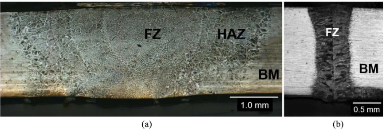
The effects of the different welding sources can be better observed from the metallographic examination of the sample cross-sections, as shown in Figure 1. Macroscopically, the width of the TIG fusion zone (TIG-FZ) was approximately 5 mm and 0.8 mm for the laser weld. The extensions of the FZs are directly related to the heat input, which is twenty-two times higher in the TIG technique.
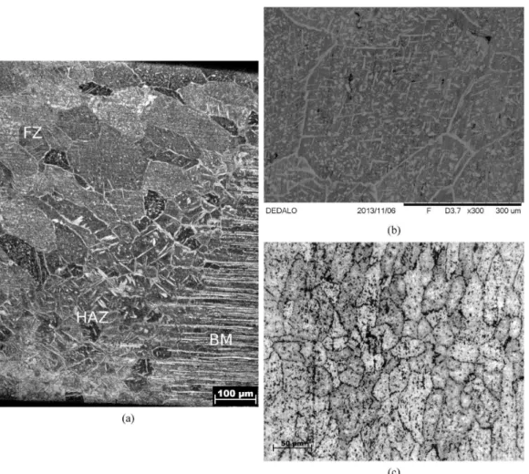
During solidiication, the ferrite phase nucleates irst, and later, the austenite phase precipitates via a solid-state reaction. Here, the austenite phase showed grain boundary allotriomorphs, Widmanstätten needles, and continuous ilms morphologies, as shown in Figure 1, similarly to Schmidt24. Under relatively slow cooling conditions, such as TIG welding, a two-phase structure may form with austenite precipitates at the grain boundaries and inside the grains. The microstructure of the TIG-FZ differs signiicantly from the base material. The original microstructure of the base material is composed of almost equal fractions of austenite/ ferrite layers, as shown in Figure 2. The heat-affected zone (HAZ, Figure 2a) presents acicular and Widmanstätten austenite needles around deformed ferrite grains as well as allotriomorphic austenite at grain boundaries6. The volume fraction of austenite in the heat-affected zone is similar to the base material, i.e., approximately 50%. The microstructure inside the fusion zone of the TIG weld can be better observed
in Figure 2b. The TIG-FZ is composed of equiaxed ferrite
grains with intergranular austenite growing in grains in the Widmanstätten phase and intergranular austenite. The volume
fraction of austenite did not change appreciably from the base material or HAZ (approximately 50%).
Laser welds are much narrower than the TIG-FZ, and the LBW-HAZ was almost undetectable. Due to the high cooling rate, the microstructure is composed of small equiaxed ferrite grains with allotriomorphic austenite at the grain boundaries and in the intergranular austenite. Few Widmanstätten needles were veriied in this case (Figure 2c).
The rapid cooling may freeze the ferrite phase well below the
ferrite-austenite transformation temperature. This retained
ferrite is unstable at ambient temperatures and may partially transform to ine austenite during cooling25. The heat-affected zone presents a complete or an incomplete transformation to ferrite, depending on how far it is from the melting boundary. The precipitation of austenite has begun just below the
ferrite-austenite transformation temperature and appears at
the grain boundaries or inside the grains with a plate-like morphology. In the laser welding case, the cooling rate was very fast, and the heat-affected zone is almost invisible.
Because the microstructures were too reined to allow for the determination of the σ phase, thermal modeling and a comparison with the literature data are necessary. Figure 3 presents the calculated thermal proiles for the TIG and laser cases with different distances from the weld centerline.
According to Li et al.5, the time-temperature-transformation of the σ-phase nucleation from the primary δ-ferrite phase in SAF-2507 DSS presents a nose at 961 °C/0.01h. Based on cooling from the homogeneous δ-ferrite range (1327 °C), the critical cooling rate is 10.2 °C/s. This value is only approximate because the cited literature only reported the TTT diagram. Considering the curves in Figure 3 and these
limitations, the cooling rates were very different in TIG and laser case.
In the TIG case, the cooling rate varied from 20.4 °C/s at a position 0.0 mm (weld centerline) to 6.4 °C/s at a position 7.47mm from the centerline. Although the cooling rate far from the centerline is below the critical cooling rate for σ-phase formation, the peak temperature is well below the ferrite-austenite loci (1000 °C). Therefore, the observation of σ-phase far from the TIG fusion zone is thermodynamically doubtful. For the LBWcase, the cooling rates are so high, ranging from 989 °C/s (position 0.0 mm) to 234 °C/s (position 1.26 mm), that the σ-phase should not occur.
Figure 2. Microstructure of the fusion and heat affected zones in (a) TIG weld near to the heat-affected zone, (b) inside the TIG-FZ and (c) laser-FZ. Optical and scanning electron microscopy.
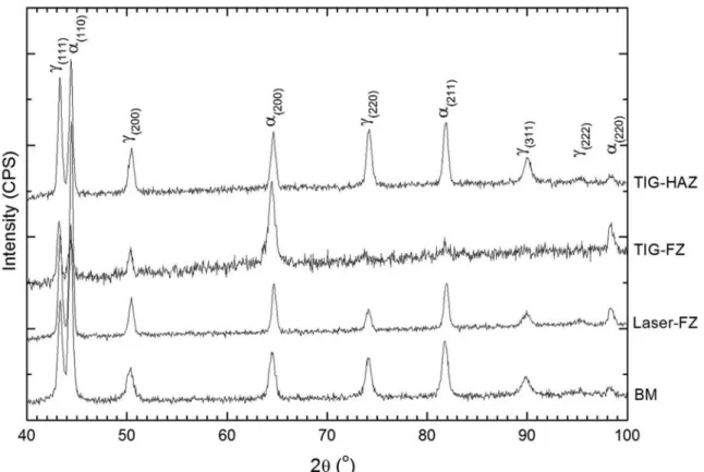
Although the thermal modeling suggests that the formation of σ-phase is improbable, it is important to obtain some real evidence about its existence because of its very detrimental effects. To achieve this goal, X-ray diffraction could give more information about the phases. Figure 4 shows diffractograms of the fusion zone of the TIG weld (TIG-FZ), the heat-affected zone of the TIG weld (TIG-HAZ), the fusion zone of the laser weld (laser-FZ) and inally the base material (BM). As shown, the diffraction patterns present peaks from austenite (γ) and ferrite (α) in all conditions. According to the PDXL software the relative fractions of ferrite were as follows: BM - 53±6%; Laser-FZ – 58.1±0.8%; TIG-FZ - 62±3% and TIG-HAZ - 44.1±0.9%. However, these numbers should be considered with care because the strong texture effects in the weldments. The amount of ferrite was about the same comparing the base material and the laser fusion zone. On the other hand, the fusion zone of the TIG weld was richer in ferrite than the BM and its heat-affected zone was poorer than the BM. The σ-phase was not veriied by the X-ray diffraction. It is known26 that the σ-phase possess a very strong line at a lattice spacing of 1.952Å, which corresponds to 46.5° in the spectra shown in Figure 4, which was not veriied.
3.2. Hardness and tensile behavior
The hardness of the base material was 280±2 HV. These values are quite similar in both the TIG and LBW fusion zones: 270±8 and 280±9 HV, respectively. For the HAZ of the TIG weld, the value was approximately 290 HV. Therefore,
the hardness values are quite similar in all regions, which could be considered a good indication of the absence of stress concentrators and hard and brittle intermetallics. The tube manufacturer indicates a maximum hardness during practical use of DSS SAF-2507 of 32 HRC18, i.e., approximately 320 HV. The hardness levels obtained here are well below this limit, so it is not expected a low toughness in the welds after LBW or TIG.
Tensile stress-strain curves for the tested samples are shown in Figure 5 for the TIG and laser-welded samples. As shown, the results are similar in terms of elastic-plastic behavior, including the tensile stress and total elongation.
The plots in Figure 5 did not present a linear elastic region
due to the shapes of the samples, which were round. Table 2 summarizes some of the mechanical properties of the samples. Because of the sample geometry (curved), the yield strength is not visible. The tensile strengths were above the value observed by Luo et al.4, indicating the grain reining behavior of micro-arc TIG and LBW compared to the SAW process. The reference values for SAF-250718 are between 800 and 1000 MPa for tensile strength and with a minimum elongation of 25%. All samples cracked in the base material. Therefore, the current weld properties are in good agreement with the manufacturer’s standards.
3.3. Electrochemical behavior
The corrosion rate for an aerated H2SO4 solution was determined for the eletroctrodes produced with the BM, LBW-FZ, TIG-FZ and TIG-HAZ. Figure 6 shows the OCP
curves for all electrodes, indicating the inal potential after
55 minutes of immersion, and Figure 7a and b shows the
micro and macropolarization curves, respectively. The electrodes exposed areas, the calculated corrosion current densities, polarization resistances and corrosion rates are listed in Table 3.
Figure 7. (a) Micropolarization and (b) Macropolarization vs. saturated calomel electrode in H2SO4 solution.
The base material (BM) had a higher open circuit potential (OCP) in the acid solution than the welded materials. Thus, when the BM and the welded metal are placed close together in an electrolyte, the BM is the cathodic part. However, according to Table 3, the BM possesses a higher polarization resistance (171 KΩ) and, thus, a lower corrosion rate (0.007 mm/year) than all other samples.
Secondary phases are considered to have a detrimental effect on pitting resistance because they or their interphase boundaries are the preferential sites for the initiation of corrosion. The reason for the increased corrosion current density is the presence of secondary phases in the welded metal. In contrast, the cooling process in LBW was so fast that the diffusion of alloying elements during welding was
limited (Figure 3). Because the elements in the FZ are
uniformly distributed, both the δ-ferrite and γ-austenite phases have similar compositions; thus, the presence of austenite in the microstructure is not detrimental to the corrosion resistance. Because the welds are more sensitive to corrosion, it is preferable to choose a situation where the welds have a more negativeOPC, as in the laser-welded SAF-2507 sample (Table 3).
The results of the electrochemical experiments on the LBW and BMsamples indicated that the corrosion current densities in the lasered samples are lower than in the BM samples. Stress relief, grain growth, changes in the chemical composition during heat treatment and, thus, a reduction of grain boundaries cause a reduction in the OCP difference between the metal/HAZ and the HAZ/weld metal and, subsequently, a reduction in the corrosion current density. Figure 5. Tensile strain-stress curves for the TIG and laser welded
samples.
Table 2. Summary of the mechanical properties of the SAF-2507
samples.
Technique Tensile strength (MPa) Total strain (%)
LBW 833 62.7
LBW 849 62.1
LBW 862 86.9
TIG 826 71.8
TIG 832 63.4
TIG 834 61.3
According to Table 3, the OCP of the TIG-FZ sample is greater than the TIG-HAZ sample. The corrosion behavior of the TIG-FZSAF-2507 (OCP=−241 mV, icor=28µA) was better than the TIG-HAZ (OCP=−273 mV, icor=97µA) up to 70 mV, manifested as a shift in the polarization resistance (42.2 to 11.7 kΩ). The corrosion behavior of the TIG-FZ SAF-2507 (corrosion rate = 0.014 mm/year) was better than the TIG-HAZ (corrosion rate = 0.05 mm/year); therefore, the TIG-FZ SAF-2507 showed a lower susceptibility to corrosion.
Comparing the base material to the resolidiied areas of the TIG welding, a twofold increase in the corrosion rate was observed (Table 3). The corrosion rate between the base material and the TIG weld in the heat-affected zone showed an increase of approximately seven times. There was an increase of approximately one and a half of the laser weld compared with the base material. The decrease in surface protection from TIG welding was more pronounced than from LBW. Therefore, the laser-welded tube had better corrosion performance than the TIG tube.
4. Conclusions
After the study, the following conclusions could be drawn:
a) Highly qualiied fusion welds using micro-tungsten inert gas and laser methods are possible;
b) The very reined microstructures of the welds are composed of almost equal amounts of austenite and ferrite phases, which is similar to the base material;
c) The heat-affected zone of the TIG weld is also composed of similar amounts of austenite and ferrite
phases;
d) Allotriomorphicaustenite grew at the grain boundaries and in the intergranular region as Widmanstätten needles and plate-like precipitates, which is different from the base material;
e) X-ray diffraction measurements and thermal modeling indicated the absence of the σ-phase in the welds;
f) In both TIG and laser welding, the tensile strength and elongation of the welds are similar to the base material and are below the limits enforced by the manufacturer of the tubes;
g) The corrosion test results revealed that the welded metal in all welded samples was the anodic part, while the base material was cathodic;
h) The welding process has a detrimental effect on the corrosion behavior of the alloy;
i) Laser welding resulted in better corrosion behavior than TIG welding.
Acknowledgements
The authors acknowledge funding from the CNPq, CAPES and FAPESP Brazilian agencies.
Table 3. Electrochemical parameters for each sample.
Material Electrode Area (cm2) OCP (mV) R
p (kΩ) icor (µA/cm
2) Corrosion rate (mm/year)
BM 0.272 -112 171 15.0 0.007
TIG-FZ 0.229 -241 42 28.0 0.014
TIG-HAZ 0.225 -273 12 97.0 0.050
LBW-FZ 0.0972 -223 110 8.5 0.010
References
1. ASM International Handbook Committee. ASM Metals Handbook.
10th ed. Materials Park: ASM; 1998. p. 2187-2189. Properties and Selection Irons Steels and High Performance Alloys 1. 2. Martins M and Casteletti LC. Sigma phase morphologies
in cast and aged super duplex stainless steel. Materials Characterization. 2009; 60(8):792-795. http://dx.doi.org/10.1016/j.
matchar.2009.01.005.
3. Pettersson C-O and Fager SÅ. Welding practice for the Sandvik duplex stainless steels SAF 2304, SAF 2205 and SAF 2507.
Sandviken; 1999. 15 p. Technical Guide, AB Sandvik Steel,
S-811 81.
4. Luo J, Yuan Y, Wang X and Yao Z. Double-Sided Single-Pass Submerged Arc Welding for 2205 Duplex Stainless Steel.
Journal of Materials Engineering and Performance. 2013; 22(9):2477-2486. http://dx.doi.org/10.1007/s11665-013-0529-8.
5. Li X, Miodownik P and Saunders N. Modelling of materials properties
in duplex stainless steel. Materials Science and Technology. 2002; 18(8):861-868. http://dx.doi.org/10.1179/026708302225004694.
6. Urena A, Otero E, Utrilla MV and Munez CJ. Weldability of a 2205 duplex stainless steel using plasma arc welding. Journal of Materials Processing Technology. 2007; 182(1-3):624-631.
http://dx.doi.org/10.1016/j.jmatprotec.2006.08.030.
7. Zhang M, Zhang SB. Observation of the keyhole during plasma arc welding. Welding Research Supplement. 1999; 53-58.
8. Mourad A-HI, Khourshid A and Sharef T. Gas tungsten arc and laser beam welding processes effects on duplex stainless steel
2205 properties. Materials Science and Engineering A. 2012; 549:105-113. http://dx.doi.org/10.1016/j.msea.2012.04.012.
9. Ion JC. Laser processing of engineering materials. Elsevier;
2005. p. 395-448.
10. Mirshekari GR, Tavakoli E, Atapour M and Sadeghian B. Microstructure and corrosion behavior of multipass gas tungsten arc welded 304L stainless steel. Materials & Design. 2014; 55:905-911. http://dx.doi.org/10.1016/j.matdes.2013.10.064.
12. Capello E, Chiarello P, Previtali B and Vedani M. Laser welding and surface treatment of a 22Cr/5Ni/3Mo Duplex Stainless Steel.
Materials Science and Engineering A. 2003; 351(1-2):334-343. http://dx.doi.org/10.1016/S0921-5093(02)00841-9.
13. Mirakhorli F, Malek Ghaini F and Torkamany MJ. Development of weld metal microstructures in pulsed laser welding of
duplex stainless steel. Journal of Materials Engineering and Performance. 2012; 21(10):2173-2176. http://dx.doi.org/10.1007/ s11665-012-0141-3.
14. Invernizzi AJ, Benedittis L and Trasatti SP. Corrosion behaviour of duplex SAF2507 in aqueous organic acid solutions. La Metallurgia Italiana. 2008; (1)23-28.
15. Nilsson JO and Wilson A. Influence of isothermal phase transformations on toughness and pitting corrosion of super duplex stainless steel SAF 2507. Materials Science and Technology. 1993; 9(7):545-554. http://dx.doi.org/10.1179/ mst.1993.9.7.545.
16. Mortezaie A and Shamanian M. Microstructure and corrosion behavior of multipass gas tungsten arc welded 304L stainless
steel. Materials & Design. 2014; 55:905-911. http://dx.doi.
org/10.1016/j.matdes.2013.10.064.
17. Yang J, Wang Q and Guan K. Effect of stress and strain on corrosion resistance of duplex stainless steel. International Journal of Pressure Vessels and Piping. 2013; 110:72-76. http://
dx.doi.org/10.1016/j.ijpvp.2013.04.025.
18. Sandvik. Tube: Duplex Stainless Steel Sandvik SAF 2507. Material datasheets -1875. Sandviken; 2008. 8 p.
19. Sandvik. Orbital weld machines model 205. 2014. Avaliable
from: <http://www.arcmachines.com/products/fusion-welding/ model-205>. Access in 25/10/2013.
20. Lima MSF, Goia FA, Riva R and Espírito Santo AM. Laser surface remelting and hardening of an automotive shaft sing a high-power fiber laser. Materials Research. 2007; 10(4):461-467. http://dx.doi.org/10.1590/S1516-14392007000400022.
21. International Centre for Diffraction Data - ICDD. Quantitative analysis: reference intesity ratio. Avaliable from <http://www.
icdd.com/resources/tutorials>. Access in: 07/11/2014. 22. ASM International Handbook Committee. ASM Metals
Handbook. Materials Park: ASM; 2003. p. 152-193. Corrosion:
Fundamentals, Testing, and Protection 13A.
23. ASTM International. ASTM G59-97: standard test method for conducting potentiodynamic polarization resistance measurements, designation: (Reapproved 2009), ASTM Customer: 1207691.
West Conshohocken. Available from: <http://enterprise.astm. org/filtrexx40.cgi?REDLINE_PAGES/G59.htm>. Access in:
18/11/2013.
24. Schmidt E. A study of austenite precipitate growth in duplex stainless steel: a research performance evaluation. [Thesis].
Department of Materials Science and Engineering, Carnegie Institute of Technology; 2005.
25. Palmer TA, Elmer JW, Wong J, Babu SS and Vitek JM. Investigation of the kinetics of the ferrite/austenite phase transformation in the HAZ of a 2205 duplex stainless steel weldment. In: Proceedings of the 6th International Conference on Trends in Welding Research; 2003; Pine Mountain, GA,
USA. p. 23-28.
26. Elmer JW, Palmer TA and Specht ED. Direct observations of
sigma phase formation in duplex stainless steels using in-situ