ISSN 1546-9239
© 2009 Science Publications
Corresponding Author: D.A. Wahab, Department of Mechanical and Materials Engineering, Faculty of Engineering, University Kebangsaan Malaysia, Malaysia
Designing for Comfort and Reliability in an Intelligent Car Seat
1
D.A. Wahab,
1N.F. Adull Manan,
2M.A. Hannan,
1S. Abdullah and
2A. Hussain
1
Department of Mechanical and Materials Engineering,
2
Department of Electric, Electronic and Systems Engineering,
Faculty of Engineering, National University of Malaysia, 43600 UKM Bangi, Selangor, Malaysia
Abstract: Today, intelligent safety systems are installed in modern cars in view of minimising road hazards. An intelligent air bag system for example, comprised several subsystems that are integrated to include the weight sensor system, image sensor system, crash sensor system and tyre pressure monitoring system. These systems when poorly positioned into the car seat, will certainly affect comfort and reliability of the car seat. This research presents the design work on an intelligent car seat, which is equipped with a load cell type-sensory system. The load cells are used to detect the weight of a passenger for the deployment of an air bag system. The proposed design is validated against displacement and stress analysis using an 80 kg load to simulate the weight of a passenger. Results from the design validation indicated that the proposed configuration and material is appropriate for use in the intelligent car seat application.
Key words: Design for comfort and reliability, intelligent car seat, intelligent safety system, load cells
INTRODUCTION
Today, the automotive industry is advancing very rapidly. Each year new and better automotive components are introduced by the automotive manufacturers in view of improving passengers safety and comfort as well as aesthetics. Intelligent Safety System (ISS) for example, is aimed at optimising passenger safety and comfort[1]. ISS is equipped with safety equipment to warn drivers on incoming road hazards. Developments related to automotive safety cost billions of dollars each year and that exclude casualties, death as well as its adverse effects to the environment[2,3].
This research presents the development work on a car seat that incorporates a load cell sensory system. The load cells are used for detecting the weight and position of the passenger for the deployment of an air bag in an ISS. The car seat is part of the improved features of the ISS for detecting road hazards. It combines several subsystems such as a weight sensor, image detector, collision system and a tyre pressure monitoring system. The subsystems, which are mostly based on sensors, are combined to provide precise information for the deployment of the air bag. The air bag will be deployed under circumstances such as hazards occurring at a specific speed, the position of the driver to the air bag source and the presence of a driver in the vehicle.
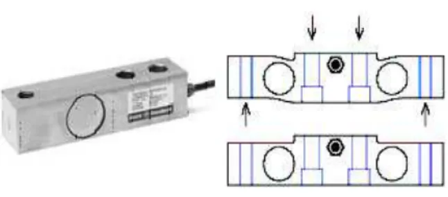
Fig. 1: Type of load cell
The design of the car seat proposed in this study takes into consideration the use of the load cell type-sensory system that are based on the principles of the Wheatstone bridge i.e. the amplifier arrangement. A wave receiver equipment converts load to electrical current as the output. The load cell is capable of accurately detecting the passenger and position of the air bag[4,5]. Figure 1 shows the type of load cell used in the application.
necessary for ergonomic application . In determining the shape and dimension of a product, the features of the human body form the basis in determining size measurements. This is known as the human factors study that is concerned with the interaction of human and products. It is therefore the objective of this study to propose an ergonomic design for a car seat that is equipped with sensory systems for the deployment of an intelligent air bag system.
DESIGN AND METHODOLOGY
This research focuses on the design aspects for ensuring comfort and reliability in the intelligent car seat. For this purpose, the configuration and materials for the car seat were identified. The design of the car seat follows the standard methodology for engineering design starting from information gathering through to concept, embodiment and detail design. Design concepts were generated based on the identified design objectives. Possible design concepts were evaluated and selected based on identified design criteria and eventually the final concept was chosen. The final concept was then validated against structural and stress analysis using a computer aided engineering software focusing on the seat cushion, frame structure and load cell platform. Each of these components is subjected to different compressive loading to represent the weight of the driver and passenger.
RESULTS AND DISCUSSION
Design of the car seat: An ergonomic design of a car seat will require data on the compatibility of human size with the car seat. Turek’s[12] guidelines on passenger comfort in a car seat as shown in Table 1 were referred to during the design of the seat cushion. The final design of the seat cushion is shown in Fig. 2.
Figure 2 shows the dimension of the car seat taking into consideration ergonomic requirements. The best position for driving comfort is lowering the knee at the same level as the thigh. In handling the foot pedal, the heels should be used instead of constantly twisting the ankle causing excessive torque to the vertebrae bones[13]. Sitting on a hard seat cushion will adversely affect the pelvic bone. According to Mills and Gilchrist[14], sitting on a flat wooden bench will cause peak pressures on the buttocks as compared to sitting
Fig. 2: Dimension of the seat cushion based on ergonomic guidelines
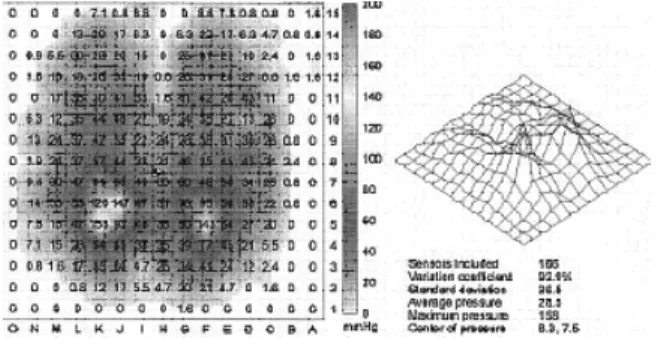
Fig. 3: Distribution of peak pressure[14]
on a soft foam cushion. They noted that such high pressures are tolerable for short periods only. Figure 3 shows the pressure contours on a thin foam cushion and the 3-D pressure map. A high peak pressure causes discomfort to the passenger, hence poor quality of driving. Choosing the appropriate material for the seat cushion is also necessary to ensure passenger comfort. For the proposed design of the car seat, the dimension of the seat cushion is 475×226×488 mm in the respective width, thickness and length.
Fig. 4: Arrangement of the load cells
Fig. 5: Location of the sensory system underneath the seat cushion
identifying the right location for the load cells and the shape of the compartment for ensuring passengers comfort as well protection to the load cells. The load cells are hard and will cause discomfort to passengers if not properly placed underneath the seat cushion.
For this purpose, a compartment of size 280×370×45 mm with a distance of 25 mm from the underside of the seat was proposed. The design allows the sensors to be loaded underneath the seat cushion. The passenger will not feel the hardness of the load cells due to the thickness of the cushion layer on top of the load cells. In order not to affect the functioning of the load cells, a thin layer of plastic sheet of 2.5 mm thickness is placed at the top and underneath the sensors. This will ensure a uniform weight distribution of the passenger. For safety as well as aesthetic reasons the load cell compartment is covered; it can however be opened or closed using the sliding mechanism.
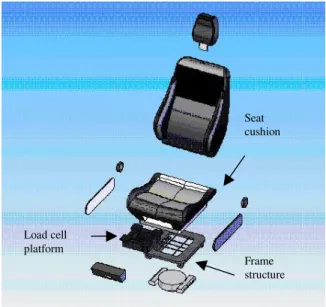
The complete design of the ergonomic car seat is shown in Fig. 6.
The following sections describe the material selection and design configuration of the car seat focusing on the three main components namely the seat cushion, sensory system platform and the seat frame. All three components were subjected to a design analysis using a load of 80 kg to represent the weight of an adult.
Load cell platform
Seat cushion
Frame structure
Fig. 6: The proposed design of the ergonomic car seat showing components under study
Material selection: Selecting the most optimum material for the seat cushion, seat frame and load cell platform was carried out using the Cambridge Engineering Selector, CES software®. The functional requirements and limitations for each of the component were specified and through manual and computational analysis, the most optimum material was identified.
For the seat cushion material, elasticity as well as stiffness is required to provide comfort. Also, the material must not be too heavy, with reasonable service life duration and cost. Most importantly, it must provide support for a stable posture. The most optimum material identified by CES® is Medium density flexible polymer foam. For the seat frame, the material must have sufficient durability to withstand the weight of a human. The material must have a suitable hardness and at a reasonable price. The material identified by CES® is Annealed Carbon Steel AISI 1025. For the load cell platform that will be subjected to compressive forces, the material must be light and of high strength. Most importantly, it shall not induce magnetic fields that can adversely affect the functioning of the load cells. The material identified by CES is High Density Polyethylene, a non-metal of high strength.
RESULTS DISCUSSION ON DESIGN VALIDATION
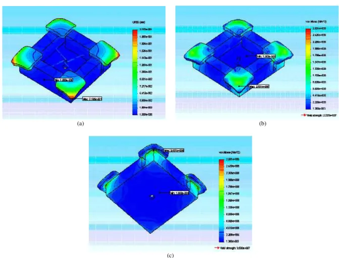
value (von-Mises) is 1.362×10 while the maximum
stress value is 2.651×10⁶ N m−2
. Maximum stress is located underneath the platform since weight is concentrated at the corner of the platform.
Seat cushion: Analysis on the seat cushion is focused on the load cell compartment that lies underneath the seat cushion. It is important to ensure that deformation of the seat cushion will not affect the functioning of the load cell sensory system. Figure 8a shows the displacement location and values for the load cell platform when subjected to a load of 784.8 N (80 kg). Results indicate that the maximum displacement value is 134.5 mm, which is concentrated at the centre of the seat cushion surface.
surface to the bottom and the weight that is concentrated at the sides.
Seat frame: The analysis is to ascertain that the steel frame located underneath the car seat has the strength and durability to withstand the passenger’s weight. Figure 9a shows the displacement location and values when subjected to a load of 784.8 N (80 kg). The maximum displacement value is 0.002283 mm located at end of the structure.
Figure 9b shows the stress distribution and location on the platform. The maximum stress value (von-Mises) is 1.492×10⁶ N m−2 located underneath the steel
structure due to weight concentration at the end of the support.
(a) (b)
(c)
(a) (b)
(c)
Fig. 8 (a-c): (a): Displacement distribution at 80 kg (b): Stress distribution at 80kg (c): Location of maximum and minimum stresses
(a) (b)
Fig. 9 (a-b): (a): Displacement distribution at 80 kg, (b): Stress distribution at 80 kg
Table 2 summarises of the displacement and stress values for the components when subjected to a load of 80 kg.
From the design analysis it was found that the maximum stress at 80kg load (at 2.651 M N m−2
the specified material i.e., High-density polyethylene at 2.520×10⁷ N m−2
or 25.2 MN m−2
i.e., only 10.5% from the yield strength of the material.
The seat cushion experienced a large displacement compared to that of the load cell platform and the steel structure. This displacement is however acceptable since the seat cushion is designed to provide comfort to passengers.
A small displacement would reflect that the material specified for the seat cushion is hard and inappropriate for use as a seat cushion. This also indicates that the seat cushion enables the load cell to respond accordingly when a load is placed on the seat cushion. The Medium Density Flexible Polymer foam is durable and has a yield strength of 6.5×10⁶ N m−2
, as such can withstand a load of 80 kg with a maximum stress of 1.757×10⁵ N m−2 or 2.7% of the yield strength.
As for the steel structure, the displacement is 0.002283 mm. The structure that uses Annealed Carbon Steel AISI 1025 with a yield strength of 3.225×10⁸ N m−2
experienced a maximum stress of only 1.492×10⁶ N m−2
or 0.46% of the yield strength when subjected to a load of 80 kg.
CONCLUSION
This study is aimed at designing for comfort and reliability in an intelligent car seat. The intelligent car seat incorporates a load cell sensory system placed underneath the seat cushion. If the load cells are not properly designed into the car seat, the reliability of the sensory system may be affected. Passengers may experience discomfort during riding.
The car seat design was analysed focusing on three main components namely the seat cushion, frame structure and the load cell platform. The analysis indicates that even though displacement occurs on the cushion, the material selected for the cushion provides comfort to the user by reducing pressure on the pelvis. The displacement experienced by the frame structure and load cell platform is however low indicating that the component did not undergo a drastic change in shape when subjected to the specified loadings. A significant change in shape will lead to fatigue and eventually failure in the components. It can be concluded from the analysis that the configuration and material selected for the car seat is appropriate for use in the ISS.
Proceeding of the IEEE International Conference on Intelligent Vehicles, pp: 570-574.
2. Gautama, S., S. Lacorix and M. Devy, 1999. Evaluation of stereo matching algorithms for occupant detection. In: Proceedings of the International Workshop on Recognition, Analysis and Tracking of Faces and Gestures in Real-Time System, pp: 177-184.
3. Devy, M., A. Giralt and A. Marin-Hernandez, 2000. Detection and classification of passenger occupancy using stereovision. In: Proceeding of IEEE Intelligent Vehicles Symposium, pp: 714-719.
4. Burn, B., 2005. The torsional sensing load cell for occupant positioning sensing. http://www.gagetek. com/autocell.pdf [15 April 2007].
5. Nozumi, S., 2004. Development of occupant classification system for advanced airbag requirement. Mitsubishi Motor Technical Review, (16): 61-64.
6. Guenaelle, P., 1995. One methodology to evaluate automotive seat comfort. In: Proceedings of the Third International Conference on Vehicle Comfort and Ergonomics, pp: 231-240.
7. Gyi, D.E., J.M. Porter and N.K. Robertson, 1998. Seat pressure measurement technologies: Consideration for their evaluation. Applied Ergonomics, 29 (2): 85-91.
8. Anderioni, G., G.C. Santambrogio, M. Rabuffetti and A. Pedotti, 2002. Method for the analysis of posture and interface pressure of car drivers. Applied Ergonomics, 33 (6): 511-522.
9. Grieco, A., 1986. Sitting posture: An old problem and a new one. Ergonomics, 29 (3): 345-362. 10. White, A.A. and M.M. Panjabi, 1990. Clinical
Biomechanics of the Spine. 2nd Edn. Philadelphia: Lippincott-Raven Publisher.
11. Pheasant, S., 1996. Bodyspace: Anthropometry, Ergonomic and Design of Work. Taylor and Francis, London.
12. Turek, J., 2000. Ergonomics Workstation Guidelines. http://www.ncsu.edu/ehs.emerg_info. html [23March 2007].
13. Thomas, G.L., 2005. How to sit: Ergonomic seating fact. http://www.trucomfort.com/howtosit/ [19March 2007].