Abstract
For deep-water long span bridges under earthquakes, the interac-tion between water and structure will inevitably induce the hydro-dynamic force on the structures. Based on the Morison potential fluid theory, a simplified calculation method of hydrodynamic force was proposed. Taken the 3rd Nanjing Yangtze River Bridge in China as the prototype, the shaking table test for the elevated pile caps was performed. And the results from the experiment and the proposed simplified calculation method were analyzed and com-pared. The main conclusions include: the natural vibration frequen-cy of the bridge in deep water is decreased, and the predominant frequency is reduced by 8.24% due to the water-structure interac-tion. In earthquake, the effect of hydrodynamic force on the dy-namic response of the deep water bridge is significant that the bending moment of the main girder is increased 7.73% and the bottom bending moment of the most adverse pile is increased 14.22%. In the seismic design of deep-water bridges, the effect of water-structure interaction should not be ignored.
Keywords
Bridge, water-structure interaction, hydrodynamic force, deep wa-ter, shaking table test.
Experiment and Calculation Method of the Dynamic
Response of Deep Water Bridge in Earthquake
1 INTRODUCTION
In order to across wider open water, bridges are developing towards longer span and deeper water (Feng 2009, Xiang 1998). Due to the long span and high pier, the bridges have a larger natural vibration period. Under earthquakes, the water acts on the underwater component of the bridge in the form of hydrodynamic force. Reflected as the viscous effect, inertia effect and diffraction effect, the hydrodynamic force may significantly change the vibration characteristics and seismic response of the bridges (Wei 2013 and Huang 2011), and even lead to girder falling and pier damage (Zhuang
Yue Li a, * Zhi Li a Qiqi Wu a
a School of Civil Engineering, North
China University of Technology, Beijing 100144, PR China
* Corresponding author: Yue Li, E-mail: [email protected]
http://dx.doi.org/10.1590/1679-78253872
2009). Therefore, as an important factor the hydrodynamic force should be considered in the seismic design of deep water bridge.
In the aspect of calculation method, many analytical approaches and numerical methods have been proposed to solve the hydrodynamic effect (Jiang 2016, Xing 2003 and Bouaanani 2010). Westergaard (1993) firstly analyzed the hydrodynamic force acting on the vertical dam under earthquake and put forward the analytical solution. Based on the analytical approaches, Liaw (1974) and Chopra (1991) deduced the analytical solution of the hydrodynamic force acting on the flexible cylinder and the gravity dam by radiation wave theory, and studied the coupling vibration effect of the surrounding water and cantilever column. Whereas, the semi analytical and semi numerical approaches could combine the advantages of analytical methods and numerical methods. Morison (1950) proposed the semi analytical solution in the form of the additional mass of the hydrodynamic force acting on the slender cylinder which diameter smaller than the wavelength of the flow, which is the Morison equation widely used by national specifications (JRA 1995, GSDHB 2008, CHSH 2008). Goto (1965) also put forward the other additional mass method by converting the hydrody-namic force into the static load under earthquake. Based on the radiation wave theory, Lai Wei (2006, 2007) proposed a semi analytical and semi numerical approach of hydrodynamic force consid-ering the elastic deformation of piers. Combined the Morison equation and the radiation wave theo-ry, Huang (2011) discussed the effect of hydrodynamic force on the pier in deep water under earth-quake. Based on the Morison equation, Li (2011) discussed the effect of hydrodynamic force on the long span girder bridges. The numerical method is a multi field coupling finite element method based on the potential fluid theory, which has been widely used in the field of dynamic fluid-structure interaction such as dams (Bathe 1999, Bouaanani 2009). Taken the piers of bridge as the target, Wei (2013) verified the validity of the numerical method based on the potential fluid theory by the experiment of the coupling system of the bridge pile group foundation and water.
2 SIMPLIFIED CALCULATION METHOD FOR HYDRODYNAMIC FORCE ON SLENDER
STRUC-TURES
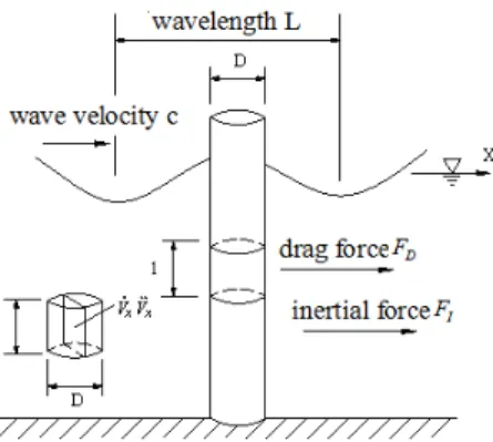
Based on the Morison's potential fluid theory (Morison 1950), it is assumed that the effect of fluid on the structure is caused by the acceleration field and velocity field, and the effect of structure on the movement of fluid could be ignored. Therefore, the hydrodynamic force acting on the column includes two components: one is the inertial force FI and the other is the drag force FD on the
col-umn due to the effect of viscous and swirl (as shown in Figure 1).
Figure 1: Hydrodynamic Forces on Cylindrical Column.
Then the hydrodynamic force on the surface of the cylinder could be defined as
C
A
u
x
u
x
2
1
x
u
V
1
C
F
F
t
z
x
F
,
,
I
D
M
D
p
(1)Here, ρ is the density of the fluid, ΔV is the volume of the submerged structure, Ap is the area
of the column section, u and are the absolute velocity and acceleration of the fluid respectively,
and are the relative acceleration and velocity of the column respectively, CM is the inertia
coeffi-cient and CD is the drag force coefficient of the fluid.
As the effect of the column on the fluid is ignored, the movement of the column will not cause the movement of the fluid. So the velocity and acceleration of the fluid are zero. The total hydro-dynamic force on the unit length of the column along the X-axis direction can be expressed as
1
(
1)
2
w M D p
F
C
Vx
C
A x x
(2)A movement equation of the entire column system under earthquake could be expressed as
1
(
1)
(
)
2
g M g D p
Here,
x
g is the acceleration of the ground motion.Previous study results (Goto 1965, Lai 2006) showed that the drag force acting on the column was much less than the inertial force under earthquake, so the hydrodynamic drag force could be negligible for most structures except some flexible structures. Therefore, a simplified method is put forward to calculate the hydrodynamic force acted on submerged columns with larger stiffness un-der earthquake. Based on the simplified method, the movement equation of the system of the sub-merged column and fluid under earthquake could be expressed as
(
1)
(
)
g M g
Mx Cx Kx
Mx
C
V x x
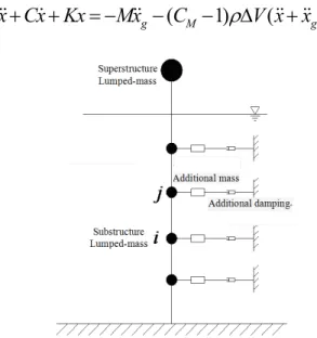
(4)Figure 2: Dynamic Analysis Model Based on the Proposed Simplified Method.
And the dynamic analysis model is shown in Figure 2. Assuming that the relative velocity of the water and the structure would be constant between two adjacent units, the force on the node i
is half of the sum of forces on the connected units. The additional mass of water Miw on the node i
could be defined as
(
1)
iw M ij
M
C
Vl
(5)Here, the node j is adjacent to node i, lij is half of the efficient length between node i and j.
Therefore, the movement equation of the entire system under earthquake can be expressed as:
(
)
g w g
Mx Cx Kx
Mx
M x x
(6)3 EXPERIMENTAL PROGRAM
3.1 Experimental Setup and Tested Specimens
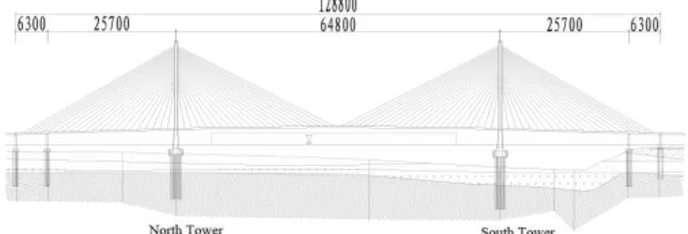
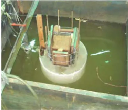
In order to validate the simplified calculation method of hydrodynamic force when investigating the dynamic behavior of bridge with pile foundation submerged in water under earthquake, the shaking table tests of the group pile foundation were carried out. The reduced scale models tested in this study derived from the pile foundation of the 3rd Nanjing Yangtze River Bridge in China. The bridge is a double cable plane and five span continuous steel box girder cable-stayed bridge with a total length of 1288m and a 648m main span. The specific layout of bridge is shown in Figure 3. The bridge has two towers with 215m height. There are 4 horizontal beams on the tower (as shown in Figure 4). The lower part of the tower is made of Chinese Grade C50 concrete and the height is 36.32m. The upper of the tower is made of Chinese Grade Q420B steel and 178.68m height. The steel component of the tower was embedded in the concrete. The steel girder is 1288m length, 37.2m width and 3.2m height (as shown in Figure 5). The girder is divided into total 89 segments and the length of every general segment is 15m.
Figure 3: General Layout of the 3rd Nanjing Yangtze River Bridge (Unit: cm).
Figure 5: General Cross Section of the Steel Box Girder (Unit: mm).
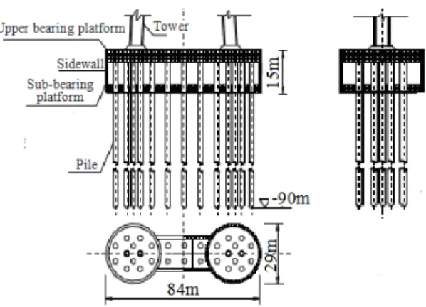
The bridge has 84m29m elevated pile caps (as shown in Figure 6). There are 30 piles under every elevated pile caps and 15 piles with 3m diameter under each round section. The maximum water depth of the elevated pile caps is 45m. The height of pile is 50m, and the diameter is 3m, the design axial force of the pile is 2000t. The equivalent consolidation depth method is used to simplify the dynamic effect of soil on the pile. The elastic modulus E of the cylindrical pile is 3.25103MPa, the density is 2500kg/m3, and the Poisson's ratio μ is 0.3. Elastic modulus Ev of the water is
2.2103MPa and the density is 1000kg/m3.
Figure 6: Layout of the South Pier of the 3rd Nanjing Yangtze River Bridge (Unit: m).
The tests were carried out at the Structure Laboratory of University of Science and Technology Beijing. This laboratory is equipped with the earthquake simulation shaking table which is served by an electrohydraulic energy control system. The platform size of the shaking table is 1.5 m×1.5 m. The maximum load capacity is 5t. The maximum horizontal driving displacement and speed are ± 200 mm and ± 500 mm/s. The maximum horizontal acceleration is ± 1.0g and the working fre-quency (f) ranges from 0.4 to 40 Hz. The dimensions of the model box are 2.0 m (L)×1.3 m (W)×1.5 m (H). The model box is made of steel frame with steel plate on the bottom.
was made of reinforced concrete and the piles were made of steel pipes. The distribution of measur-ing points is shown in Figure 8.
(a) pile model in air (b) pile model in water
Figure 7: Testing Model.
Figure 8: Distribution of Measuring Points (Unit:mm).
Wave absorbing devices were installed on the sides of the water tank which were perpendicular to the direction of the input waves in order to eliminate the reflected waves.
Physical Quantity Similarity Coefficient Physical Quantity Similarity Coefficient
Length Sl=1.50 Inertial Force SF =2.7510-3
Modulus of Elasticity SE=6.87 Hydrodynamic SP = Sl =0.02
Equivalent Density S=6.87 Flexural moment SM=5.510-5
Acceleration S=1 Frequency Sf=33.5
Stress S= SE=6.87 Time St=0.03
Strain S= S/SE=6.87 Displacement S= Sl =0.02
3.2 Experimental Results
First of all, the effect of fluid-structure interaction on the natural vibration characteristic of the pile foundation in experiment was analyzed, and the results were compared with the proposed simplified numerical method of the hydrodynamic force. Here, D represented the difference between the exper-imental and the calculated values (as seen the equation (7)). The natural vibration frequency of the model in air and water are shown in Table 2. Both in air and in water, the natural frequencies of the model obtained through the simplified numerical method basically coincide with the results from the experiment, so does the natural vibration period. After all, all differences do not exceed ± 3%. At the same time, estimated by half power method, the damping ratio were 0.006 and 0.012 in air and in water, respectively.
100%
Experimental results - Calculation results D
Calculation results
(7)
Methods In air In water
Frequency(Hz) Period(s) Frequency(Hz) Period(s)
Experimental Value 10.100 0.099 6.881 0.145
Calculated Value 9.891 0.101 7.022 0.142
D (%) -2.08 2.13 2.03 -2.07
Table 2: Comparison of Natural Vibration Obtained from the Simplified Method and the Shaking Table Test.
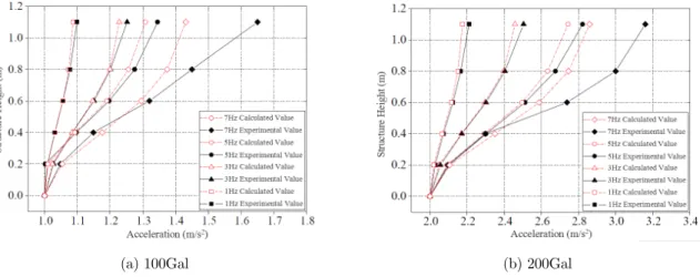
Under harmonic waves and earthquake waves, the dynamic responses of the model in water were analyzed with the experiment and the simplified method. Here, 1Hz, 3Hz, 5Hz and 7Hz har-monic waves, and Tianjin and Takatori earthquake waves were input as the seismic load. The dis-tribution of the peak horizontal acceleration along the height of the model are compared in Figure 9-Figure 11, here the peak accelerations of the waves were adjusted to 100Gal and 200Gal.
(a) 100Gal (b) 200Gal
(a) 100Gal (b) 200Gal
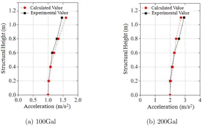
Figure 10: Distribution of the Peak Horizontal Acceleration under Tianjin Earthquake.
(a) 100Gal (b) 200Gal
Figure 11: Distribution of the Peak Horizontal Acceleration under Takatori Earthquake.
By comparing the dynamic responses, the peak horizontal acceleration of the model in water by the experiment and the simplified calculation method were close, and there was only a certain devi-ation in some cases. The maximum devidevi-ations under 100Gal/7Hz and 200Gal/7Hz harmonic loads are 15.4% and 10.5% respectively, the maximum deviations under the Tianjin wave and the Taka-tori wave are 9.0% and 12.5% respectively.
4 STUDY OF THE CABLE-STAYED BRIDGE BASED ON THE SIMPLIFIED CALCULATION
METHOD OF HYDRODYNAMIC FORCE
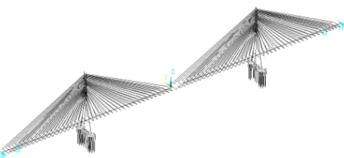
element is used to simulate the cables, the solid element is used to simulate the lower cap. In the model, the influence of the adjacent spans is ignored. The connection between the main bridge and the approach span is free translation in the longitudinal direction, and free rotation in longitudinal and horizontal directions. In addition, the embedded depth of the group piles is 3 times of the pile diameter under scouring line in the model. The analysis model of the bridge is shown in Figure 12. The boundary conditions of the model are listed in Table 3.
Figure 12: Three-dimension Analysis Model of the Bridge.
Position Degree of freedom
x y z x y z
Pile end under main tower 1 1 1 1 1 1
Main tower and main girder 0 1 1 1 0 0
Side pier, auxiliary pier and main girder 0 1 1 1 0 0
Note: axes x is the longitudinal direction, axes y is the horizontal direction, axes z is in the vertical direction. θx, θy, θz are the
rotation around axes x, y and z respectively. “0” presents freedom, and the “1” presents constraint or fixed.
Table 3: Boundary Condition of the Bridge Model.
4.1 Effect of Hydrodynamic Force on the Natural Characteristic of the Bridge
4.2 Effect of Hydrodynamic Force on the Dynamic Response of the Bridge under Earthquake
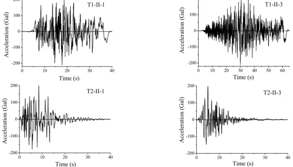
In order to investigate the effect of fluid-structure interaction on the dynamic response of the bridge in earthquake, 4 seismic waves belonging to the Type1 and the Type2 respectively were selected to simulate the far-fault and near-fault earthquakes according to the Code for Bridge Design V in Ja-pan (1995). As the effect of the hydrodynamic force on the seismic response of the bridge under vertical earthquake could be ignored (Uniform Building Code 1997), only the horizontal waves were put in the model. And the peak acceleration of the seismic waves was adjusted to 200Gal according to the seismic design intensity. The adjusted waves are shown in Figure 13.
0 10 20 30 40
-200 -100 0 100 200 T1-II-1 Ac cele ration (Gal ) Time (s)
0 10 20 30 40 50 60
-200 -100 0 100 200 T1-II-3 Time (s) Acce lera tion (G al)
0 10 20 30 40
-200 -100 0 100 200 Time (s) Acce leration ( G al) T2-II-1
0 10 20 30 40
-200 -100 0 100 200 200 Time (s) Ac cele rati on (G al) T2-II-3
Figure 13: Acceleration Time-history Graph of Seismic Waves.
4.2.1 Effect of Hydrodynamic Force on the Main Girder
In order to reflect the influence of hydrodynamic force on the internal force of the cable-stayed bridge, the coefficient R (as seen in the equation (8)) is used to express the influence of the hydro-dynamic force on the maximum earthquake response of the bridge. As shown in Figure 14, the hy-drodynamic force has a significant influence on the internal force of the main girder.
- 100%
Maximum dynamic response with water Maximum dynamic response without water R
Maximum dynamic response without water
(8)
reaches 7.74% under T2-II-3 wave. Similar to the shear force, the bending moment of the main girder has increased by 7.73%, while in the middle the moment reduces about 3.89%.
-600 -400 -200 0 200 400 600
-8 -6 -4 -2 0 RAx ia l Fo rc e(% ) Longitudinal coordinate(m) T1-II-1 T1-II-3 T2-II-1 T2-II-3
(a) Axial force
-600 -400 -200 0 200 400 600 -20 -10 0 10 20 RSh ear F orce (% ) Longitudinal coordinate(m) T1-II-1 T1-II-3 T2-II-1 T2-II-3
(b) Shear force
-600 -400 -200 0 200 400 600 -20 -10 0 10 20 RBe nd in g M om ent (% ) Longitudinal coordinate(m) T1-II-1 T1-II-3 T2-II-1 T2-II-3
(c) Bending moment
Figure 14: Distribution of R in Main Girder.
4.2.2 Effect of Hydrodynamic Force on the Main Tower
shear force of the main tower has reduced significantly in position of the main girder and the bot-tom of tower. Under T1-II-1 wave, the shear force at the tower botbot-tom in water decreases 11.03% than without water, which reduced 12.56% in the position of main girder. The effect of hydrody-namic force on the bending moment of the main tower is similar to the shear force, which reduces by 25.54% under T2-II-1 wave.
-50 0 50 100 150 200
-4 -3 -2 -1 0 1 2
T2-II-3 T2-II-1 T1-II-3 T1-II-1
RAxial Force(%)
Hei ght(m) -50 0 50 100 150 200
-16 -12 -8 -4 0 4
RShear Force(%)
He ig ht (m ) T2-II-3 T2-II-1 T1-II-3 T1-II-1 -50 0 50 100 150 200
-28 -24 -20 -16 -12 -8 -4 0 4
RBending Moment(%)
He ig ht (m ) T2-II-3 T2-II-1 T1-II-3 T1-II-1
(a) Axial force (b) Shear force (c)Bending moment
Figure 15: R Distribution of Internal Force in Main Tower.
4.2.3 Effect of Hydrodynamic Force on the Adverse Pile
As an important component, the pile foundation will take part in the fluid-structure interaction directly. Here, taken the most adverse position of the pile cap as an example, the distribution of the R along the pile height is analyzed (as shown in Figure 16).
-100 -90 -80 -70 -60 -50
5 10 15 20
T2-II-3 T2-II-1 T1-II-3 T1-II-1
RAxial Force(%)
Hei gh t(m) -100 -90 -80 -70 -60 -50
5 10 15 20
T2-II-3 T2-II-1 T1-II-3 T1-II-1
RShear Force(%)
Height (m) -100 -90 -80 -70 -60 -50
5 10 15 20
T2-II-3 T2-II-1 T1-II-3 T1-II-1 RBending Moment(%) He ig ht (m )
(a) Axial force (b) Shear force (c) Bending moment
As shown in Figure 16, the hydrodynamic force has a significant influence on the internal force of the most adverse piles under the longitudinal earthquake wave. Due to the hydrodynamic force, the maximum axial force at the bottom of the pile is increased 18.50% under T2-II-3 wave and 13.85% under T1-II-1 wave. The maximum axial force at the bottom of the pile is increased 18.03% under T2-II-1 wave and 8.99% under T1-II-1 wave. The maximum bending moment at the bottom of the pile is increased 14.22% under T1-II-3 wave and 7.96% under T2-II-1 wave.
5 CONCLUSIONS
Based on the Morison potential fluid theory, a simplified calculation method of hydrodynamic force acting on the group piles under earthquake was proposed. Taken the foundation of the Nanjing Yangtze River bridge as the prototype, the simplified method was verified by experiment. At the same time, the effect of hydrodynamic force on the dynamic response of the bridge was investigated. The main conclusions are followed:
(1) By comparing with the dynamic response of the pile foundation in shaking table tests, the proposed simplified hydrodynamic force calculation method was validated.
(2) Due to the effect of hydrodynamic force, the natural vibration characteristics of the pile cap structure was changed. The natural vibration period of the structure surround with water was increased more 40% than without water.
(3) As a flexible and light structure, the natural vibration period of the cable-stayed bridge in deep water is more sensitive to the hydrodynamic force under earthquake. Due to the hy-drodynamic force, the first natural frequency of the bridge decreased by 8.24%, and the other frequencies also decreased. The influence of hydrodynamic force on the natural vibra-tion characteristics of cable-stayed bridges should be considered in the seismic design. (4) Depend on the characteristic of the earthquake waves, the internal force of the bridge main
girder was changed by hydrodynamic force. In addition, the displacement peak of the main girder in longitudinal direction was increased, and the occurrence time was lagged. Under the longitudinal earthquake waves, besides of the increased axial force at the bottom of the tower, the shear force and bending moment of the main tower decreased obviously, whereas the longitudinal displacement increased significantly. And the internal force of the most ad-verse piles under the tower increased significantly.
(5) Under earthquakes, the hydrodynamic force has a great influence on the different compo-nent of the cable-stayed bridge depending on the types of the earthquake. So it is necessary to consider the hydrodynamic force in the seismic design of the cable-stayed bridge.
Acknowledgments
References
M. Feng. (2009). China`s Major Bridges. Proceedings of the International Association for Bridge and Structural Engineering Symposium (IABSE`09), Shanghai, China, pp.1-24.
Xiang Haifan. (1998). Major Sea-crossing Bridge Engineering on Coastal High-grade Expressways. Journal of Tongji University.Vol.26, No.2, pp.109-113.
Wei K, Yuan W C. (2013). Experimental and Numerical Assessment of the Three-dimensional Modal Dynamic Re-sponse of Bridge Pile Foundations Submerged in Water. Journal of Bridge Engineering, Vol.18, No.10, pp.1032-1041. Huang Xin, Li Zhongxian. (2011). Influence of Hydrodynamic Pressure on seismic response of bridge piers in deep water. China Civil Engineering Journal, Vol.44, No.1, pp.65-73.
Zhuang Weilin, Liu Zhenyu, Jiang Jinsong. (2009). Earthquake induced damaged analysis of highway bridges in Wenchuan earthquake and countermeasures. Chinese Journal of Rock and Mechanics and Engineering, Vol.28, No.7, pp. 1377-1387.
Jiang Hui, Wang Baoxi, Bai Xiaoyu, et al. (2016). Response property of deep-water bridge pier under near-fault earthquakes and inspection of calculation methods of hydrodynamic effect. Journal of Chang`an University, Vol.36, No.4, pp.48-57.
J. T. Xing, W. G. Price, Y.G.Chen.(2003). A mixed finite-element finite-difference method for nonlinear fluid-structure interaction dynamics. I. Fluid-rigid fluid-structure interaction. Proceedings of the Royal Society A, Vol. 459, No.2038, pp.2399–2430.
N. Bouaanani, B. Miquel. (2010). A new formulation and error analysis for vibrating dam-reservoir systems with upstream transmitting boundary conditions. Journal of Sound and Vibration, Vol. 329, No.10, pp.1924-1953.
Westergaard H M. (1933). Water pressure on dams during earthquakes. Transactions of the American Society of Civil Engineers, 1933, Vol.98, pp.418-433.
Liaw C.Y., Chopra A.K. (1974). Dynamic of towers surrounded by water. Earthquake Engineering and Structural Dynamics, No.3, pp.33-49.
Chopra A.K., Goyal A. (1991). Simplified earthquake analysis of intake-outlet towers. Journal of Structural Engi-neering, Vol.117, No.3, pp.767-788.
Morison J.R., O’Brien M.P., Johnson J.W. (1950). The force exerted by surface wave on piles. Petroleum Transac-tions, Vol.19, pp.149-158.
Japan Road Association. (1995). Code for Bridge Design V (Seismic Design), The Japanese MARUZEN Press, Tokyo. Ministry of Communications of China. (2008). Guidelines for seismic design of highway bridges, JTG/T B02-01-2008, Beijing, China.
CCCC First Harbour Consultants Co., LTD. (2008). Code of Hydrology for Sea Harbour (JTJ 213-98). Beijing: China Communications Press.
Goto H., Toki K. (1965). Vibration characteristics and aseismic design of submerged bridge piers. Pro.3rd world conference on earthquake engineering. New Zealand.
Lai Wei, Wang Junjie, Wei Xiao. (2006). The shaking table test for submerged bridge pier. Earthquake Engineering and Engineering Vibration, Vol.6, pp.165-172.
Lai Wei, Zheng Tiehua, Lei Yong. (2007). The effect of hydrodynamic drag force in Morison equation on the seismic response of piles. Sichuan Building Science, Vol.4, pp.163-168.
Bouaanani N, Lu F Y. (2009). Assessment of potential-based fluid finite elements for seismic analysis of dam-reservoir systems. Computers and Structures, Vol.87, pp.206-224.
Wei K, Yuan W C. (2013). Seismic analysis of deep water pile foundation based on three-dimensional potential based fluid elements. Journal of Bridge Engineering, Vol.3, pp.1-10.