Pedro Daniel da Silva Ramôa
Design of a knee orthosis locking system
Pedr o Daniel da Silv a R amôa 2 Design of a knee or thosis loc king sys tem
Universidade do Minho
Escola de Engenharia
Tese de Mestrado
Engenharia Mecatrónica
Trabalho efectuado sob a orientação do
Professor Doutor João Paulo Flores Fernandes
e co-orientação do
Professor Doutor Jaime Francisco Cruz Fonseca
Pedro Daniel da Silva Ramôa
Design of a knee orthosis locking system
Universidade do Minho
Escola de Engenharia
Acknowledgements
In first place, I would like to thank my parents, my participation in this project was possible due to their hard work. I would also like to dedicate this thesis to Cidália, my brother Rui and to my sister-in-law Paula, their support during this project was very important to me, they were always there for me. To company Thermopista, a big thank you, specially to Alexandre and Susana. I would also like to thank the people from CT2M, specially to Pedro Moreira.
To my supervisors, Paulo Flores and Jaime Fonseca, I would like to thank them for their guidance during this project.
Abstract
The main goal of this work was to design a mechatronic locking system for a Stance Control Knee Ankle Foot Orthosis (SCKAFO). This mechanism should be able to perform two different functions. The first one is to lock the orthosis during the stance phase of human gait, in which contact between the foot and the ground exists. The second function deals with the unlock of the orthosis during the swing phase, in which there is no contact between the foot and the ground, allowing the flexion of the knee.
Biomechanics of human gait play an important role in the mechanical design of the locking system, since the motion characteristics associated with pathological and non-pathological exhibit different behaviors. Thus experimental gait studies was considered for pathological and non-pathological, in order to analyze the kinematic properties(joint angles and trajectories) and kinetic (ground reaction forces, joint forces and moments) of the human gait.
In the context of the present work sensors were used to detect the key points that characterize the human gait, allowing for the correct mechanism performance. These sensors are placed in anatomical relevant locations and calculate, not only the joint angles, but also the angular acceleration. The data read by these sensors is interpreted by a microcontroller that controls the actuation system in order to lock or unlock the mechanism. An innovative solution is presented here, which differs from the currently available solutions or in the scientific literature. The new approach is able to work without foot sensors and cables used with the purpose to lock/unlock the orthosis. With this approach it is expected that the locking/unlocking operation will be effective, safe and quick for the user.
Resumo
O objetivo principal deste projeto foi desenvolver um sistema mecatrónico para ortóteses do tipo Stance Control Knee Ankle Foot Orthosis (SCKAFO). Este mecanismo permite realizar duas funções distintas. A primeira consiste no bloqueio da ortótese durante a fase de apoio da marcha humana, onde se verifica contacto entre o pé e o solo. A segunda função incide no desbloqueio da ortótese durante a fase de balanço da marcha humana, onde não se verifica contacto entre o pé e o solo, permitindo a flexão do joelho.
Os conceitos biomecânicos da marcha humana assumem uma elevada importância no projeto mecânico deste mecanismo, uma vez que as características associadas à marcha natural e patológica demonstram comportamentos distintos. Por isso serão consideradas análises experimentais, com o objetivo de caracterizar cinematicamente (ângulos e trajetórias das articulações e segmentos anatómicos) e cineticamente (forças de contacto entre o pé e o solo, momentos e forças nas articulações) a marcha humana.
No contexto do presente trabalho foram utilizados sensores de forma a detetar pontos-chave da marcha humana, permitindo um correto funcionamento do mecanismo. Os sensores serão colocados nos segmentos anatómicos de maior interesse para este estudo e irão possibilitar o cálculo dos ângulos das articulações e as suas acelerações angulares. A informação gerada pelos sensores será interpretada por um microcontrolador, que irá controlar um sistema de atuação, permitindo bloquear ou desbloquear a ortótese. Com este trabalho, pretende-se desenvolver uma abordagem inovadora, que difere de todas as soluções comerciais e apresentadas na literatura científica. Esta solução permite um funcionamento sem a necessidade de recorrer a sensores plantares (colocados no pé) e sem presença de cabos ao longo do membro inferior. Com esta abordagem pretende-se desenvolver um mecanismo que realize a operação de bloqueio e desbloqueio de modo eficaz, seguro e rápido para o seu utilizador.
“First of all, let me assert my firm belief that the only thing we have to fear is fear itself -nameless, unreasoning, unjustified terror which paralyzes needed efforts to convert retreat into advance.”
Contents
1 Introduction 1
1.1 Motivation . . . 3
1.2 Objectives and Thesis Structure . . . 4
1.3 State-of-the-Art . . . 6
2 Biomechanics of the Human Gait 19 2.1 Human Gait: Non pathological . . . 21
2.2 Human Gait: Pathological . . . 25
2.3 Experimental Studies of the Human Gait . . . 29
2.4 Chapter Summary . . . 34
3 Preliminary study of the locking mechanism 35 3.1 Problem description . . . 37
3.2 Material . . . 38
3.3 Mechanical Solutions . . . 39
3.4 Chapter Summary . . . 56
4 Preliminary study of the electronics 57 4.1 Sensors . . . 59
4.2 Actuators . . . 63
4.3 Data Acquisition . . . 66
4.4 Chapter Summary . . . 68
5 Development of a New Concept of Locking System for an Orthosis SCKAFO 69 5.1 Operation and Performance of the Mechanical Device . . . 71
5.2 Construction of the Physical Prototype . . . 73
5.3 Electronic System Implementation . . . 76
CONTENTS
6 Conclusions and Future Work 89
6.1 Conclusions . . . 91 6.2 Future Work . . . 93
A Ratchet 1 99
A.1 Dimensions . . . 101 A.2 Stress Analysis . . . 103
B Ratchet 2 105 B.1 Dimensions . . . 107 B.2 Stress Analysis . . . 110 C Slot Mechanism 111 C.1 Dimensions . . . 113 C.2 Stress Analysis . . . 115 D Generic Mechanism 117 D.1 Dimensions . . . 119 E Schematics 125 E.1 Microcontroller . . . 127 E.2 Sensors . . . 128 E.3 Voltage Regulator . . . 129
List of Figures
1.1 Becker’s mechanical orthosis . . . 6
1.2 Foot movements . . . 7
1.3 UTX’s mechanism . . . 7
1.4 Ottobock Free Walkand corresponding mechanism . . . 8
1.5 Becker SafetyStride’s mechanism . . . 9
1.6 Fillauer SPLand respective mechanism . . . 10
1.7 Fillauer SPL2and respective mechanism . . . 11
1.8 Horton Stance Control KAFOand respective mechanism . . . 11
1.9 Becker GX-Kneeand SafetyStride with GX-Assist . . . 12
1.10 Becker Load Response and corresponding mechanism . . . 12
1.11 Becker E-Knee and corresponding mechanism . . . 13
1.12 E-Knee’s sensors . . . 13
1.13 Sensor Walk’s mechanism . . . 14
1.14 Ottobock - Sensor Walk . . . 15
1.15 Sensor Selection Switch . . . 15
1.16 Ottobock - E-MAG . . . 16
2.1 Gait cycle . . . 21
2.2 Joints angles . . . 23
2.3 Laterial trunk bending . . . 26
2.4 Circumduction . . . 26
2.5 Pathological gaits . . . 27
2.6 Excessive Knee Flexion . . . 27
2.7 Abnormal foot contact . . . 28
2.8 Non pathological gait . . . 29
2.9 Knee angle on normal gait . . . 29
LIST OF FIGURES
2.12 Knee angle with crouch gait . . . 31
2.13 Ankle and hip angle with crouch gait . . . 31
2.14 Equinus gait . . . 32
2.15 Knee angle with equinus gait . . . 32
2.16 Ankle and hip angle with equinus gait . . . 33
2.17 Knee angle with stiff knee gait . . . 33
3.1 Ratchet/Pawl mechanism . . . 39
3.2 Ratchet/Pawl mechanism positions . . . 39
3.3 Ratchet dimensions . . . 40
3.4 Ratchet - stress distribution . . . 41
3.5 Ratchet 2 mechanism . . . 42
3.6 Pawl 2 and 3 . . . 42
3.7 Ratchet 2 dimensions . . . 43
3.8 Ratchet 2 - stress distribution . . . 44
3.9 Ratchet 2 with double pawl - Stress distribution . . . 44
3.10 Ratchet 2 - Transverse section . . . 45
3.11 Pawl 2 - Stress distribution . . . 45
3.12 Pawl 3 - Stress distribution . . . 46
3.13 Ratchet housing . . . 46
3.14 Slot mechanism . . . 47
3.15 Slot mechanism dimensions . . . 47
3.16 Slot mechanism - Stress distribution . . . 48
3.17 Pawl 3 - Stress distribution . . . 48
3.18 Assembly with slot mechanism . . . 49
3.19 Generic mechanism . . . 49
3.20 Generic mechanism - different models . . . 50
3.21 Generic mechanism dimensions . . . 50
3.22 Generic upper part - Stress distribution . . . 51
3.23 Generic lower part v1 - Stress distribution . . . 51
3.24 Generic lower part v2 - Stress distribution . . . 52
3.25 Stress distribution . . . 53
3.26 Locking pin . . . 54
3.27 Tradicional mechanism . . . 54
LIST OF FIGURES
4.2 RC Servo control . . . 64
4.3 ATmega128RFA1 . . . 66
4.4 General view of the software . . . 67
5.1 Generic mechanism - v1 . . . 71
5.2 Switching operation . . . 71
5.3 Sensor measurement . . . 72
5.4 Built mechanism . . . 73
5.5 Elements of part one . . . 73
5.6 Elements of part two . . . 74
5.7 Measured values . . . 74
5.8 Shaft . . . 75
5.9 KAFO with the built mechanism . . . 75
5.10 iSensor Inclinometer/Accelerometer Evaluation Board . . . 76
5.11 CMR3000 - Necessary components . . . 77
5.12 PCB with sensors . . . 78
5.13 ATmega128RFA1 schematic . . . 79
5.14 ATmega128RFA1 Board - communication by wire . . . 80
5.15 ATmega128RFA1 Board - wireless communication . . . 80
5.16 Voltage regulator . . . 81
5.17 Built sensor board . . . 82
5.18 Built microcontroller board . . . 82
5.19 Installed boards . . . 83
5.20 Installed microcontroller board . . . 83
5.21 Unstable mechanism . . . 84
5.22 Broken wiring . . . 85
5.23 Connecting between the microcontroller and the sensors . . . 85
5.24 Batteries voltage . . . 86
5.25 Voltage in the microcontroller . . . 86
A.1 Ratchet 1 . . . 101
A.2 Pawl 1 . . . 102
A.3 Reaction Force and Moment on Constraints . . . 103
A.4 Result Summary . . . 103
B.1 Ratchet 2 . . . 107
LIST OF FIGURES
B.4 Reaction Force and Moment on Constraints . . . 110
B.5 Result Summary . . . 110
C.1 Slot mechanism . . . 113
C.2 Pawl 3 . . . 114
C.3 Reaction Force and Moment on Constraints . . . 115
C.4 Result Summary . . . 115 D.1 Upper mechanism . . . 119 D.2 Lower mechanism - v1 . . . 120 D.3 Lower mechanism - v2 . . . 121 D.4 Lower mechanism - v3 . . . 122 D.5 Lower mechanism - v4 . . . 123
E.1 ATmega128RFA1 Board - communication by wire . . . 127
E.2 PCB with sensors . . . 128
List of Tables
2.1 Gait cycle timing: Female . . . 22
2.2 Gait cycle timing: Male . . . 23
3.1 Stainless Steel 304 composition . . . 38
3.2 Stainless Steel 304 characteristics . . . 38
4.1 Accelerometers - Analog Devices . . . 60
4.2 Accelerometer - Bosch Sensortec . . . 60
4.3 Accelerometers - VTI Technologies . . . 61
4.4 Inclinometers - Analog Devices . . . 61
4.5 Gyroscopes - Analog Devices . . . 62
4.6 Gyroscopes - VTI Technologies . . . 62
4.7 RC Servos . . . 65
4.8 Stepper Motors - Portescap . . . 65
5.1 Sensor PCB cost . . . 79
Abbreviations
FA Feet Adjacent HR Heel Rise
I2C Inter-Integrated Circuit IC Initial Contact
IMU Inertial Measurement Unit KAFO Knee Ankle Foot Orthosis OI Opposite iInitial contact OT Opposite Toe off
PCB Printed Circuit Board PWM Pulse Width Modulation
SCKAFO Stance Control Knee Ankle Foot Orthosis SPI Serial Peripheral Interface
TO Toe Off
Chapter 1
Introduction
Introduction
1.1
Motivation
The muscular weakness of the lower limbs induces difficulties in the knee flexion/exten-sion movement which results in a gait disorder. According to Moreira and Flores (2011) the gait disorder can be the result of several diseases, such as: peripheral neurological diseases, central neurological diseases and muscular diseases. A person with muscular weakness does not have the necessary muscular strength to maintain the knee at full extension during the entire stance phase, that is the contact between the foot and the ground exists. Thus a theoretical aid is required to help people to be able to keep the knee fully extended during gait.
According to Russell et al. (1997), in 1994 there were 989 thousand people using knee braces in the United States of America, which represents 0,35% of the total population, estimated in 260 million. In Portugal, it is know that 6.10% of the population has some type of disability, and 24,59% of all disabilities are motor related. In 2001 there were 610 thousand people with disabilities in Portugal (INE, 2002).
Currently, it is known that the number of different solutions to compensate the muscular weakness of the lower limbs is still small. In Portugal the most common solutions available in the market to solve this problem are the wheelchair and the KAFO (Knee-Ankle-Foot-Orthosis). The wheelchair has two negative effects. The first one is a slowdown in the physiotherapy process because the person stays seated down most of the day without using the muscles of the lower limbs. The second one is the need to adapt the house with ramps or elevators, making it wheelchair accessible. The KAFO solution does not need these requirements and limitations. In turn, the KAFO device is a static orthosis that does not allow the flexion of the knee while walking compensating the muscular weakness. This type of orthosis is becoming an obsolete model, the impossibility of flexing the knee during the swing phase is a great disadvantage. According to Bernhardt et al. (2006), the percentage of KAFOs rejection is between 58% and 78% due to several reasons.
Some companies such as Ottobock and Becker introduced to the market a new type of orthosis. The SCKAFO has one advantage compared to the KAFO that is, it unlocks the orthosis during the swing phase allowing to flex the knee and has the same behaviour of KAFO during the stance phase. This type of device is called a dynamic orthosis. However, the SCKAFO orthosis are still in an early stage of development. Thus, the main motivation for this work comes from the interest to contribute for the development of this
Introduction
1.2
Objectives and Thesis Structure
This work aims to develop a mechatronic locking system for a Stance-Control-Knee-Ankle-Foot-Orthosis (SCKAFO) which will be different from the ones currently avail-able, mainly in what concerns with the need to include fast sensors and cables. With this approach also intends to perdict the locking of the mechanism, making available a larger period for the locking system to act correctly.
The specific goals of this work can be listed as follows: • To perform an exhaustive study of the available SCKAFOs; • To characterize the human gait with and without pathologies; • To design a new mechanical system for orthosis locking system;
• To develop an electronic system that allows for the control and actuation the orthosis locking system;
• To build a data acquisition in order to access the influence of the developed locking system in the human gait;
• To develop of a functional prototype for verification and validation purpose.
The present dissertation is divided in six main chapters described below.
Chapter one presents the characterization of state of the art in order to evidence the different solutions by the companies with commercial solutions. In addition, a brief discussion on this thesis contribution can be found in this chapter.
Chapter two deals with the description of the lower limbs elements, followed by studies on the non-pathological human gait and pathological gait as well. Special emphasis is given to both bibliographical and experimental studies.
Chapter three describes the problem to be solved, the limitations and assumptions that the locking system must fulfill. Furthermore, in this chapter the proposed mechanical solutions and their characteristics are analyzed taking in account the critical points of the mechanism and the maximum strength. In this chapter will also be explained the reasons
Introduction
Chapter four shows the electronic parts suitable for this project, such as sensors or microcontrollers are discussed. The fundamental reasons to select the components are presented in this process. The data acquisition software developed is also demonstrated in this chapter.
In Chapter five the new concept of locking mechanism is presented as well as the corresponding performance. In this chapter the materials, the costs and the process of the construction of the physical prototype are discussed. The relation between the electronic system and the locking mechanism can also be found in this chapter. Finally, all the tests performed as well as the concept validation is object of study in this chapter.
The Chapter six contains the issues addressed in the conclusions and the future work are presented.
In Appendices A to D it is possible to see the technical drawings and summary of the results of stress simulations. In Appendix E is presents the schematics from the developed boards.
Introduction
1.3
State-of-the-Art
As result of the technology evolution over the last decades, the quality of the orthosis has been increasing. The use of new versatile and lighter materials improved the functionality and comfort of the orthosis without compromising the safety of the user. The use of new materials also allowed to improve the orthosis aesthetically.
At the end of the 80’s decade and beginning of 90’s decade of last century, the first SCKAFOs were presented. However with the introduction of electronics, the orthosis gained new capabilities that would not be possible before, because they were purely mechanical devices.
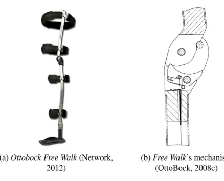
The first mechanical SCKAFO was presented in 1989 by Becker Orthopedic company. The UTX model was the first of a generation of mechanical SCKAFOs (Edeer and Martin, 2010). This UTX with some improvements is currently available. Since 1989, other pure mechanical SCKAFOs were introduced namely, Becker FullStride and SafetyStride, or Ottobock Free Walk. Figure 1.1 shows the mechanical SCKAFOs developed by Becker Orthopedic. In this type of orthosis the locking system is activated by a movement of the lower limb, usually is the dorsiflexion (Figure 1.2a). This type of orthosis demonstrate a major disadvantage, a person with foot dropping is unable to activate the locking system. In spite of the aesthetically differences, the working principle is the same, the movement of dorsiflexion is responsible for the locking/unlocking of the mechanism (Bedard, 2010).
(a) Becker UTX (b) Becker SafetyStride (c) Becker FullStride
Introduction
(a) Dorsiflexion (b) Ankle rotation
Figure 1.2: Foot movements
The UTX and the FullStride models are presented in Figure 1.1, and they have a similar locking system to the Ottobock Free Walk as it is shown in Figure 1.4b, This locking system is composed by a ratchet/pawl mechanism as Figures 1.3a and 1.3b illustrate.
(a) Locked mechanism (b) Unlocked mechanism
Figure 1.3: UTX’s mechanism (Yakimovich et al., 2009)
This mechanical orthosis have a cable along the shank, visible in Figures 1.1 and 1.3, which is moved according to the movement of the ankle. According to Yakimovich et al. (2009), it is necessary 10◦ of dorsiflexion to unlock this orthosis. When the user is performing the dorsiflexion, the cable follows the movement of the ankle which pulls away the pawl from the ratchet and consequently, unlocking the orthosis allowing the flexion of the knee. In turn, to lock the orthosis, the knee must be totally extended and dorsiflexion should not exist.
Introduction
There are other fundamental issues associated with the UTX orthosis, mainly (Bedard, 2010):
• The typical UTX orthosis weight less than two kilograms and has several design variations suiting the diferent types of diseases;
• This model is indicated to: Quadriceps weakness as a result of Poliomyelitis; Multiple Sclerosis; Cerebrovascular Accident; Femoral Nerve; Incomplete SCI; Inclusion Body Myositis; Genu recurvatum;
• The user must have muscular force in the lower limbs equal or greater than Grade 3, that is, the joint can move against the gravity;
• The user must weight less than 120kg and the knee at full-extension must be at least 10◦.
(a) Ottobock Free Walk (Network, 2012)
(b) Free Walk’s mechanism (OttoBock, 2008c)
Figure 1.4: Ottobock Free Walk and corresponding mechanism
The fundamental information about the Free Walk orthosis can be listed below: • The Free Walk orthosis weight is 780 grams; (OttoBock, 2008c)
• This model is indicated to: Central nervous system disorders (Stroke, brain tumors, craniocerebral injury, multiple sclerosis, and others); Spinal cord diseases (Injury in the spinal cord, Myatrophic lateral sclerosis, Post-polio syndrome, Post-polio
Introduction
• The Free Walk model have two variations, one to users with a bodyweight up to 80kg, and other to users with a bodyweight up to 120kg; (OttoBock, 2008b) • The knee in full-extension must be at least 10◦; (OttoBock, 2008c)
• The user must have muscular force in the lower limbs equal or greater than Grade 3. (OttoBock, 2008c)
The SafetyStride model from Becker has a different mechanism from the remaining of the presented mechanical SCKAFOs. Instead of a mechanism composed by a ratchet and a pawl, this model has a clutch and a lever (see Figure 1.5). With the clutch, the orthosis is able to lock in any position without the need of having the knee fully extended. This is a major advantage when compared with other mechanical SCKAFOs. The lever locks the orthosis during the swing phase (when the knee is flexed and there is no contact between the foot and the ground), allowing only the movement of extension of the knee. At the end of the stance phase, the lever unlocks the orthosis. This working principle is similar to the Fillauer orthosis, illustrated in Figure 1.6.
Figure 1.5: Becker SafetyStride’s mechanism (Orthotics, 2012b)
The Becker orthosis gives the following information about the SafetyStride (Bedard, 2010):
• The SafetyStride is indicated for people with: Quadriceps weakness as a result of Poliomyelitis; Multiple Sclerosis; Cerebrovascular Accident; Femoral Nerve and Incomplete SCI; Inclusion Body Myositis; Genu recurvatum;
• The weight limit is 100kg;
Introduction
The company Fillauer presented a mechanical SCKAFO, called Stance Phase Lock (SPL) which uses the same mechanism of Becker UTX but with the working principle of the Becker SafetyStride. According to Yakimovich et al. (2009) the locking mechanism is actuated by gravity. When the thigh is anterior to the body the weight pawl falls into the ratchet locking the orthosis, as shown in Figure 1.6b. With the thigh posterior to the body, the weight pawl will fall away from the ratchet (see Figure 1.6c), unlocking the orthosis, allowing the flexion of the knee.
(a) Fillauer SCKAFO (Cascade, 2012a)
(b) Locked mechanism (Yakimovich et al., 2009)
(c) Unlocked mechanism (Yakimovich et al., 2009)
Figure 1.6: Fillauer SPL and respective mechanism
Fillauer launched to the market a new orthosis, named Stance Phase Lock 2 (see Figure 1.7a), developed by Basko Healthcare, a Fillauer affiliate in The Netherlands. The locking mechanism, illustrated in Figure 1.7b, is very similar to the prior model, with some improvements, namely: it has two locking positions (0◦and 15◦); it has a cylindrical bumper with extended wear; and Teflon bushings for sideloading. These characteristics improve the locking mechanism safety, increase the durability and reduces the friction.
Stance Phase Lock 2indications and contraindications are listed below:
• The Stance Phase Lock 2 is indicated for people with: Post-polio; Spinal involve-ment; Cerebral vascular accident; Peripheral paresis/paralysis; Nerve inflamma-tions; Neurological failures; Myopathies; Multiple sclerosis. (Fillauer, 2012) • Contraindications: Central paresis/paralysis, Hip flexion contracture. (Fillauer,
Introduction
(a) Fillauer SCKAFO
(Cascade, 2012b) (b) SPL2 mechanism (Fillauer, 2012)
Figure 1.7: Fillauer SPL2 and respective mechanism
The mechanism from Horton’s SCKAFO, illustrated in Figure 1.8 has a different working principle from the Becker’s or Ottobock’s SCKAFO. In this model the locking mechanism is activated by the contact between the foot and the ground. With the contact the stirrup is forced to move upwards, causing the pushrod to move the cam into the friction ring, locking the orthosis. When the contact between the heel and the ground no longer exists, the stirrup moves downwards by the force of gravity moving the cam away from the friction ring, unlocking the orthosis and allowing to the person to flex the knee (Yakimovich et al., 2009).
(a) Horton SCKAFO (Orthotics, 2012a)
(b) Mechanism (Yakimovich et al., 2009)
Introduction
Beckerhas two other mechanical orthosis, namely the GX-Knee and the other is Load Response. GX-Knee comes with a pneumatic spring to help the knee extension and can be used alone (see Figure 1.9a) or with Becker FullStride and SafetyStride as GX-Assist (Figure 1.9b). The GX-Knee orthosis does not have locking mechanism, the only purpose of this orthosis is to assist the knee extension movement. This mechanism is similar to the ones used to the elevation of cars trunks. The Load Response has a similar mechanism to the SafetyStride, it is equipped with a preloaded spiral torsional spring that mimics the ability of ther quadriceps muscle to absorb ground reaction forces from heel strike (see Figure 1.10).
(a) Becker GX-Knee (b) Becker SafetyStride with GX-Assist
Figure 1.9: Becker GX-Knee and SafetyStride with GX-Assist (Bedard, 2010)
(a) Becker Load Response (b) Load Response’s mechanism
Introduction
According to Edeer and Martin (2010), SCKAFOs controlled by a microcontroller, such as Becker E-Knee or Ottobock Sensor Walk were introduced. The E-Knee model (see Figure 1.11a) uses a electromagnetic mechanism (see Figure 1.11b) to lock the orthosis with foot sensors to control the orthosis, as it is shown in Figure 1.12. When the pressure sensors on the foot detects contact with the ground, the electromagnetic coil is activated and forces the contact between the two ratchet plates allowing the motion only in one way (knee extension). When the pressure sensors no longer detect the contact between the ground and the foot, the coil is deactivated and the spring forces the separation between the two sprocket wheels.
(a) Becker E-Knee (Bedard,
2010) (b) E-Knee mechanism (Yakimovich et al., 2009)
Figure 1.11: Becker E-Knee and corresponding mechanism
The E-Knee model is equipped with four foot sensors as shown in Figure 1.12, one placed on the big toe (sensor 1), one located on the first metatarsal (sensor 2), one situated on the fifth metatarsal (sensor 3), and one placed on the heel (sensor 4).This set sensors is used because the foot touches the ground differently depending on the disease. For instance, a person with foot drop has a different contact area between the foot and the ground when compared to a person with lateral trunk bending.
Introduction
Becker E-Kneeadditional features, namely:
• The Becker E-Knee is indicated to people with: Quadriceps weakness as a result of Poliomyelitis; Multiple Sclerosis; Cerebral vascular Accident; Femoral Nerve; Incomplete SCI; Inclusion Body Myositis (Bedard, 2010);
• Contraindications: Users with bodyweight superior to 100kg; Spasticity in hip, knee or ankle; Fixed varus or valgus deformity at the knee superior to 15◦; Substantial leg length discrepancy (Bedard, 2010).
Ottobock Sensor Walkhas five sensors, four located on the foot and one placed at the knee level. Sensor Walk uses a wrap spring clutch as locking mechanism as it is shown in Figure 1.12. When the contact between the foot and the ground does not exist (end of the stance phase) by the sensors placed on the foot, the microcontroller unlocks the mechanism making it a free swing orthosis. At the middle of the swing phase, the knee sensor detects the motion of the shank and the microcontroller will lock the orthosis, allowing only the extension movement and blocking the flexion movement.
Figure 1.13: Sensor Walk’s mechanism (Irby et al., 2004)
Figure 1.14 presents the Sensor Walk. The highlight goes to element G in the Figure 1.14b namely, the Sensor Selection Switch. Sensor Walk allows to chose which foot sensor triggers the microcontroller to unlock the orthosis, as it is shown in Figure 1.15.
Introduction
The Sensor Walk has some important additional characteristics (Healthcare, 2010b): • The Sensor Walk maximum user bodyweight is 136kg;
• Sensor Walk users must have muscular force in the lower limbs equal or greater than Grade 3 and a step length over the opposite foot.
(a) Ottobock Sensor Walk (b) Sensor Walk diagram
Figure 1.14: Ottobock - Sensor Walk (Healthcare, 2010a)
The Sensor Selection Switch (see Figure 1.15) has advantages and disadvantages. The main advantage is that it allows to save energy because only one sensor is energised. The disadvantage is that the selected sensor has to be the right one that triggers the mechanism, if it is not the correct one, this situation will cause performance problems.
Introduction
The Ottobock created a device called E-MAG Control which is a locking mechanism that can be assembled with other orthosis from Ottobock company. E-MAG is an automatic locking mechanism without being controlled by the movement of the ankle or by sensors located on the foot. The gait cycle is detected by two gyroscopes, which read the angular accelerations from the lower limb and according to the values those accelerations the orthosis is locked or unlocked. In Figure 1.16a is shown the various parts that compose the E-MAG are listed below (OttoBock, 2008a):
1. Knee joint with bearings; 2. Electromagnetic joint; 3. End position sensor;
4. Electronic part (sensor, microncontroller, and others); 5. Buttons to manual operation;
6. Batteries (not shown);
7. Auto-calibration and test buttons.
(a) E-MAG (b) E-MAG Control System
Figure 1.16: Ottobock - E-MAG (OttoBock, 2008a)
The E-MAG was a working principle similar to E-Knee or Sensor Walk is controlled by a microcontroller, which requires a battery to supply the locking mechanism because it is a mechatronic device instead of a purely mechanical device like Free Walk or UTX.
Introduction
The control system by E-MAG that is displayed in Figure 1.16b, has (OttoBock, 2008a):
1. Knee joint with bearings; 2. Electromagnetic joint; 3. End position sensor;
4. Electronic part (sensor, microncontroller, and others); 5. Remote control to manual locking and unlocking; 6. The remote control can be installed on the waist;
7. Feedback system is composed by LEDs to ensure that is locked; 8. 2.4Ghz microcontroller for wireless communications;
9. Manual operation
Becker also presented E-MAG Active, an orthosis that is equipped with E-MAG Control and the bodyweight of the user limit is 85kg. This orthosis is indicated for persons with poliomyelitis, post-polio syndrome, or partial paraplegia. It is also indicated for persons that need a higher mobility.
Chapter 2
Biomechanics of the Human Gait
2.1
Human Gait: Non pathological
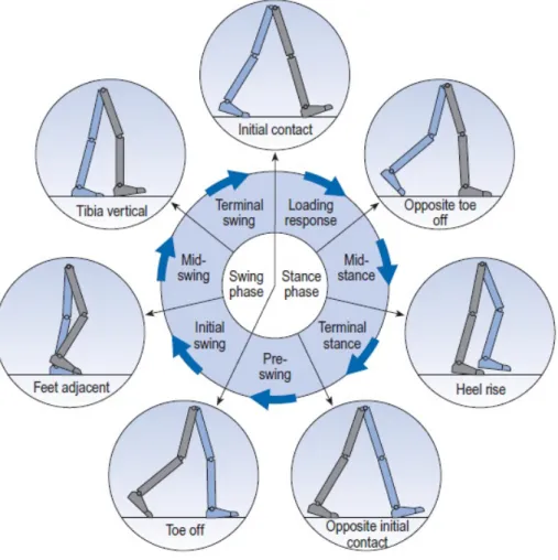
In order to better understand the human gait, it is necessary to analyze the gait cycle and the corresponding phases and sub phases. The gait cycle can be divided in two parts: the swing phase and the stance phase. The swing phase can be described as the part of the gait cycle where there is no contact between the ground and the foot. The stance phase begins in the exact instant when the heel touches the ground and ends when the toe rises from the ground, interrupting the contact between the foot with the ground.
Figure 2.1: Gait cycle (Whittle, 2007)
In Figure 2.1, several parts of the human gait are illustrated. The swing phase can be divided in three sub-phases:
• Initial swing • Mid-swing • Terminal swing
Biomechanics of the Human Gait
The stance phase is divided in four sub-phases: • Loading response
• Mid-stance • Terminal stance • Pre-swing
The sub-phases above described are separated by seven instants as it is shown in Figure 2.1:
• Initial contact (IC); • Opposite toe off (OT); • Heel rise (HR);
• Opposite initial contact (OI); • Toe off (TO);
• Feet adjacent (FA); • Tibial vertial (TV).
The transition between swing phase and stance phase happens in the instant named initial contact, in this situation the point of contact between the ground and the foot is trough the heel. The opposite transition occurs when the instant named toe off initializes the swing phase.
According to Whittle (2007), the range of the human gait cycle time is between 0,80 seconds and 1.48 seconds. The values depend on gender and age. In Table 2.1 it is presented the duration of the women gait cycle, in Table 2.2 it is presented the the men gait cycle duration. Thus, the women’s gait are less susceptible to aging.
Table 2.1: Gait cycle timing: Female (Whittle, 2007) Age (years) Cycle time (s)
13 - 14 0.80 - 1.17 15 - 17 0.83 - 1.20 18 - 49 0.87 - 1.22 50 - 64 0.88 - 1.24 65 - 80 0.88 - 1.25
Biomechanics of the Human Gait
The women’s minimum gait cycle duration varies from 0,8 seconds (from 13 to 14 years) to 0,88 seconds (from 65 to 80 years), 0,08 seconds of difference. The women’s maximum gait cycle time is between 1,17 and 1,25 seconds, the same 0,08 seconds of difference. In men’s gait cycle the differences are larger. The minimum gait cycle time is between 0,81 (from 13 to 14 years) seconds and 0,96 seconds (from 65 to 80 years), 0,15 seconds of difference. The men’s maximum gait cycle time goes from 1,20 seconds to 1,48 seconds, 0,28 seconds of difference. This aspects shows that men gait are more influenced by aging.
Table 2.2: Gait cycle timing: Male (Whittle, 2007) Age (years) Cycle time (s)
13 - 14 0.81 - 1.20 15 - 17 0.85 - 1.25 18 - 49 0.89 - 1.32 50 - 64 0.95 - 1.46 65 - 80 0.96 - 1.48
There is another important issue that should be taken in account namely, the joint angles. The joint angles are very relevant to human gait analysis, by retrieving the angles of the various joints it is possible to know in which part of the human gait the person is situated. In Figure 2.2, is shown the evolution of the joints during a entire cycle is illustrated.
(a) Hip (b) Knee (c) Ankle
Figure 2.2: Joints angles (Whittle, 2007)
Figure 2.2a shows that in the initial contact the hip angle is close to 30◦. From IC to OI the angle of the hip keeps lowering to values around -20◦. In the transition from stance phase to swing phase (given by Toe Off) the angle is not in the lower value anymore. The
Biomechanics of the Human Gait
Figure 2.2b shows that in the IC the knee is almost fully-extended. After the IC, the knee flexes slightly in the beginning of the stance phase. With lifting of heel the knee starts to flexing until the maximum value in the initial swing, nearly 50◦, then the knee starts extending to repeat the gait cycle.
Finally, the ankle (see Figure 2.2c) stays almost in the same position, except the negative peak in the initial swing, this is moment when the person rises the foot from the ground.
Biomechanics of the Human Gait
2.2
Human Gait: Pathological
There are several diseases that can affect the normal gait of a human being, these diseases can be divided into three main groups: central neurological diseases; peripheral neurological diseases; and muscular diseases. The central neurological diseases can be subdivided into six (Moreira and Flores, 2011):
• Multiple sclerosis • Cerebral palsy • Parkinson disease • Brain injury • Stroke
• Spinal Cord Injury
In turn, the diseases that belong to the peripheral neurological diseases group are as follows (Moreira and Flores, 2011):
• Poliomyelitis
• Post-polio syndrome • Spina bifida
• Poly neuropathy • Stroke
• Spinal Cord Injury
Finally, the muscular diseases can be listed as (Moreira and Flores, 2011): • Duchenne muscular dystrophy
• Becker’s muscular dystrophy • Myasthenia gravis
These diseases produce an abnormal gait, which may vary according to the type of disease. Lateral trunk bending is one of the abnormal gaits, in this situation it is normal for the patient to bend the torso sideways to reduce the pressure in the hip joint while supporting the weight only in one leg. When the person starts the swing phase with one leg, the torso leans towards the other leg, making easier the movement of swing of the first
Biomechanics of the Human Gait
Figure 2.3: Laterial trunk bending (Craig, 2012)
The common reasons to this abnormal gait are: Painful hip, hip abductor weakness, abnormal hip joint, wide walking base and unequal leg length. There is also anterior and posterior trunk bending, in these cases the torso moves erratically in the sagittal plane. With anterior trunk bending the person flex the torso in the stance phase to compensate the muscular weakness of the muscles responsible for the movement of knee extension. The posterior trunk bending is the inverse movement of the anterior trunk bending where the person moves the torso backwards in order to compensate the muscular weakness of the muscles responsible for the movement of hip extension.
Some users of lower limbs orthosis have functional leg length discrepancy. In order to compensate this problem, it is frequently used one of these abnormal gaits: circumduc-tion, hip hiking, steppage and vaulting. Circumduction is the circular movement that the person of the swing leg to compensate the leg discrepancy, as it is shown in Figure 2.6.
Biomechanics of the Human Gait
With the hip hiking gait (see Figure 2.5a) the person moves the swinging leg side of the hip upwards to compensate the leg discrepancy. The steppage (see Figure 2.5b), is the gait abnormality where the person flex the knee and the hip more than on a natural gait. In the gait with vaulting (see Figure 2.5c) the stance phase is made on the person’s toes, with this the person gains height, and does not needing to over-flex the knee or the hip.
(a) Hip hiking (b) Steppage (c) Vaulting
Figure 2.5: Pathological gaits (Whittle, 2007)
The excessive knee extension/flexion is another pathological gait. If the person has excessive knee extension the stance phase is not normal, instead of a normal stance phase as shown in Figure 2.2, the person extend the knee to a negative angle. With excessive knee flexion, the person can not fully extend the knee in the stance phase, originating a abnormal gait.
Biomechanics of the Human Gait
Abnormal foot contact is also a pathological gait very important to the development of an orthosis, because the orthosis performance depends on the movement of the dorsiflexion that is able to unlock the orthosis (e.g. Becker UTX). There exits three types of origins for abnormal foot contact: talipes calcaneus, talipes equinus and talipes equinovarus, as it is shown in Figures 2.7a, 2.7b, and 2.7c, respectively. The talipes calcaneusreduces the time of stance phase in that foot, therefore causes an asymmetrical gait. If a person has talipes equinus, the first contact between the foot and the ground is the entire foot or the metatarsal instead of the heel, this causes a problem to the orthosis that is activated by the foot sensors. With the talipes equinovarus the weight is supported by the outside of the foot.
(a) Talipes calcaneus (b) Talipes equinus (c) Talipes equinovarus
Figure 2.7: Abnormal foot contact (Dorland, 2007)
Abnormal foot rotation consists of the rotation of the foot during the swing phase, this pathology can cause a disturbance in the readings of the typical knee sensors, such as gyroscopes or accelerometers.
It must be noticed that there is also others diseases that affects children and causes a pathological gait, namely:
• Metatarsus varus: Adduction of the forefoot • Genu varum: Leg bowing
• Blount’s disease: Growth disorder of the shank or tibia
• Developmental Dysplasia of the Hip (DDH): The femur is not attached firmly to the hip
Biomechanics of the Human Gait
2.3
Experimental Studies of the Human Gait
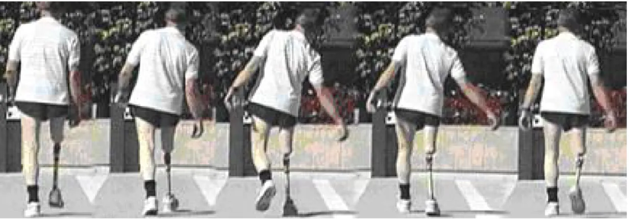
In order to complement the information of the human gait given in the subchapters 2.1 and 2.2 it is necessary to add experimental studies of the human gait. A person with a non pathological gait, as the one shown in Figure 2.8, it is possible to see the different leg positions during the gait.
Figure 2.8: Non pathological gait (NCBI, 2012)
The evolution of the knee angle can be defined as it is illustrated in the Figure 2.9, the grey curve demonstrates the normal pattern while the green curve shows the experimental study made by Whittle (2007). In this case, both gates are very similar only with small differences, the experimental gait (green trace) is shorter than the normal pattern, the maximum flex angle in the stance phase is smaller than the normal pattern, and it has a hyperextension of the knee from the IC to the loading response.
Biomechanics of the Human Gait
In a normal gait, when the initial contact occurs the knee is fully-extended. During the loading response and mid-stance there is a small flexion of the knee. After the mid-stance (approximately at 40% of the gait cycle) the knee is extended once again until the heel rising. With the heel rising, the knee follows that movement and compensates by flexing the knee. During the swing phase (from 48% until 90% of the gait cycle) the knee stays flexed, extending only to repeat the initial contact once again.
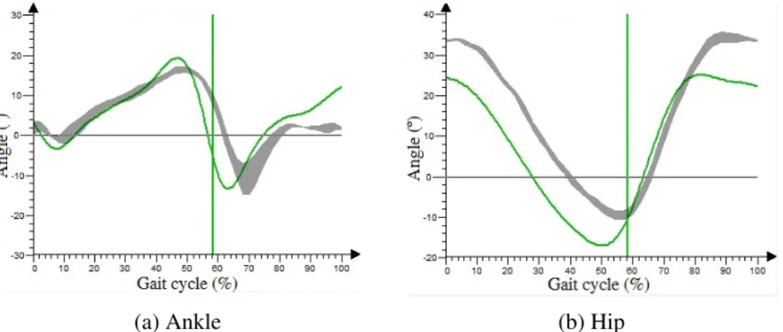
The movement of the ankle, this experimental case is very similar to the normal pattern (see Figure 2.10a). The hip has the same behaviour comparing to the normal pattern but with a negative difference of 10◦in the first 50% of the gait cycle (Figure 2.10b).
(a) Ankle (b) Hip
Figure 2.10: Ankle and hip angle on normal gait (Whittle, 2007)
Figure 2.11 shows a pathological gait called crouch gait. This particular gait is defined by an excessive knee and hip flexion in swing and stance phase. The crouch gait is one of the effects caused by cerebral palsy.
Biomechanics of the Human Gait
The angle of the knee (see Figure 2.12) with crouch gait is almost constant comparing with the normal gait. The minimum value is approximately 62◦, while the maximum value is nearly 80◦, this clearly shows the over flexing of the knee. At the beginning of the stance phase or initial contact, the knee angle is 62◦, rapidly rises to 70◦ during the loading response and keep rising (more slowly) up to 78◦ at the mid-swing when the feet are adjacent, then drops again to the initial value during the mid-swing and terminal swing.
Figure 2.12: Knee angle with crouch gait (Whittle, 2007)
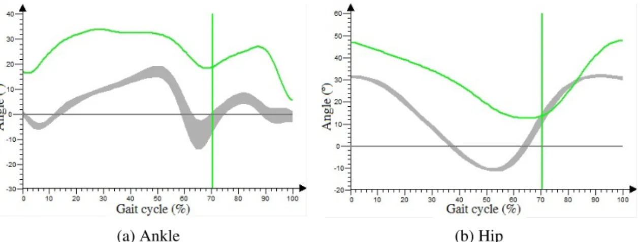
The ankle movement of the crouch gait (see Figure 2.13a) has the same behaviour of the ankle in the normal gait, but has a difference: the ankle is over flexed in the pathological gait. The hip (see Figure 2.13b) has also a similar behaviour to the normal gait, as result of increased stance phase, the pathological swing phase presents a lag in relation to the normal gait (Whittle, 2007).
(a) Ankle (b) Hip
Biomechanics of the Human Gait
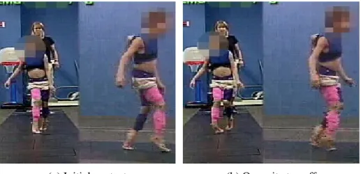
Equinus gait is another pathological gait caused by cerebral palsy. In this situation the person is unable to control the dorsiflexion of the foot, placing only the toes and the metatarsal heads on the ground. Figure 2.14 shows a child with equinus gait, specifically in two instants: Initial contact (see Figure 2.14a) and Opposite toe off (see Figure 2.14a). It is possible to observe that when the right foot (or pink leg) of the person touches the ground can not endure the weight of the body forcing a leg sliding to the outside.
(a) Initial contact (b) Opposite toe off
Figure 2.14: Equinus gait (Whittle, 2007)
The dynamics analysis (see Figures 2.15 and 2.16) shows that the ankle is always extended which will lead to a disturbance in the rest of the lower limb. In the knee the behaviour is almost the same with the exception of the terminal swing, the behaviour of the child’s foot requires this movement of the knee to compensate the incapability of dorsiflexion, so the child overflex the knee (Whittle, 2007).
Biomechanics of the Human Gait
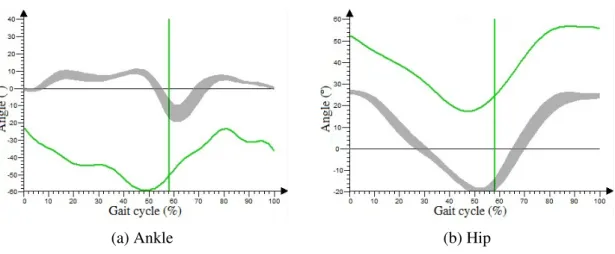
Figure 2.16a shows the child’s inability of dorsiflexion in which, the angle is always bellow 0◦ in the entire gait cycle and the maximum value read was -23◦, which is less than the minimum value in the natural gait (-14◦). The hip (see Figure 2.16b), has exactly the same behaviour of a non pathological gait with a over flexion of approximately 25◦ during the entire gait.
(a) Ankle (b) Hip
Figure 2.16: Ankle and hip angle with equinus gait (Whittle, 2007)
The stiff knee is another pathological gait caused by cerebral palsy. In this abnormal gait, the knee is the most affected articulation of the lower limbs. Comparing with the normal gait, the ankle and the hip stay the same. As visible in the Figure 2.17, the angle of the knee in the swing phase is much smaller than in the natural gait, the maximum angle is even smaller than the knee in the stance phase. This shows the incapability of controlling the knee flexors. The gait behaviour is the same of the Figure 2.6 (circumduction).
Biomechanics of the Human Gait
2.4
Chapter Summary
In this chapter a lower limb description was presented and the pathologies that affects them were also described. The human gait includes two main phases: stance phase and swing phase. In turn, these two phase can be subdivided into seven parts, these parts are devided by seven movements that defines the end of one part and sets the beginning of the next. The gait cycle times through the different ages and genders was also discussed.
The three main type of diseases were discussed. A list of the central neurological diseases, peripheral neurological diseases and muscular diseases were made, also can be found how these diseases affects the human gait.
Experimental studies performed by some authors were discussed in this chapter with a comparison to the normal pattern and to the theoretical data. These studies include the results of some diseases in the articulations and how it is possible to identify the diseases at naked eye according to the gait.
Chapter 3
Preliminary study of the locking
mechanism
Preliminary study of the locking mechanism
3.1
Problem description
The main goals when designing a functional SCKAFO are: allowing knee flexion during the swing phase and immobilizing it during the stance phase. According to Moreira et al. (2011) and Yakimovich et al. (2006b) a SCKAFO must accomplish several requirements in addition to the main goals:
• To switching between phases in less than 6ms;
• To switch from lock to unlock without requiring a fully-extended knee; • To be silent or at least the most quiet possible;
• To allow knee extension at anytime and knee flexion movement up to 110◦in order to allow the user to climb stairs and sit;
• To be as light as possible, preferably with a weight less than 2kg;
• In cosmetic terms, the orthosis should be discrete and should be appealing to the user, this reduces the chances of late rejection;
• The knee joint mechanism should not have more than 2cm of thickness; • The orthosis should resist to a moment of 77Nm (90kg user);
• Resist to fatigue and have a mean-time of six months between the maintenance. In resume the orthosis should be light, noiseless, durable and with a fast reaction time. The knee joint mechanism should be produced from a material of high hardness that allows to withstand the forces to which the mechanism is subjected. This type of mechanism is made of metallic materials, such as steel. Usually these type of mechanisms are made from steel with treatment to increase the hardness and also the corrosion resistance. The steel increases the weight of the mechanism but has a better strenght/weight ratio compared to the aluminium or other common metal.
The thickness of the mechanism should as small as possible. The companies that produce electro-mechanical orthosis are leaving this part to second plan due to the emphasis given to the reliability of the locking system. The size is compromised, but by ignoring it the companies ensure that the orthosis has a strong locking mechanism capable of support the patients weight.
Preliminary study of the locking mechanism
3.2
Material
The metal selected for the manufacturing and tests was the Stainless Steel - Grade 304, which is an inexpensive and widely used metal. According to AZoM (2012), eFunda (2012), and ASM (2012) the Stainless steel 304 is composed as described in Table 3.1.
Table 3.1: Stainless Steel 304 composition
Weight (%) C Mn Si P S Cr Mo Ni N
min - - - 18.0 - 8.0
-max 0.08 2.0 0.75 0.045 0.030 20.0 - 10.5 0.1
In general, metals can also be defined according to others characteristics, such as mechanical, physical and thermal characteristics. Density and yield strength are two of those properties. The values of their properties are used, not only to better understand this metal, but also to perform computational simulations in Autodesk Inventor. According to AZoM (2012), eFunda (2012), and ASM (2012) the Stainless steel 304 characteristics are as listed in Table 3.2.
Table 3.2: Stainless Steel 304 characteristics
Property Value
Ultimate Tensile Strength (MPa) 515 (minimum) Yield Strength (MPa) 205 (minimum)
Poisson’s Ratio 0.29
Density (kg/m3) 8000
Elastic Modulus (GPa) 193 Thermal Expansion (mm/m/◦C) 17.2 Thermal Conductivity (W/m.K) 16.2 Specific Heat (J/kg.K) 500
Preliminary study of the locking mechanism
3.3
Mechanical Solutions
The mechanisms utilized in the orthosis considered in this work can have different configurations and geometries. The first objective of this work was to study different mechanisms to create a basis for comparison between them in order to be able to select the most adequate solution.
Figure 3.1: Ratchet/Pawl mechanism
Thus, the first presented mechanism consists of a two parts, namely a ratchet and a pawl as Figure 3.1 shows. This mechanism can lock the orthosis at any angle, eliminating the need to fully extend the knee. In the transition from stance phase to swing phase, a motor with small dimensions pulls the pawl away from the ratchet allowing to the user flex the knee (see Figure 3.2a). In the sub-phase initial swing the knee reaches the maximum flexion moment, and at this instant the motor releases the pawl back into the ratchet allowing the extension movement and blocking the flexion movement (see Figure 3.2b). The pawl should bs assisted by a spring that accelerates the locking movement and does not allow for the pawl move away from the ratchet while is in the locked position.
(a) Unlocked (b) Locked
Preliminary study of the locking mechanism
The main dimensions of this mechanism are presented in the Figure 3.3. The diameter of the ratchet is less than 30 mm, and has a hole of 10 mm for the main shaft, that connects the lower part of the orthosis to the upper part. The thickness of the ratchet is equal to 10 mm, which leaves 10 mm to the housing and other parts in order to follow the requirements advised by Moreira et al. (2011) and Yakimovich et al. (2006a). The outer diameter can be smaller, but a smaller mechanism will have less resistance to the applied moments to the mechanism during operation. A compromise between size and strength should be taken in account.
Figure 3.3: Ratchet dimensions
The pawl (see appendix A) has a height of 10 mm and a minimum thickness of 10 mm. At the center of rotation of the pawl a motor shaft is connect, in the drawing is defined with 10 mm in length and with a diameter of 2 mm. This values may vary according to the chosen motor, for instance, a Radio Control Servo (RC Servo) can not be connect directly to the pawl because is too long. In this case the motor is differently located and it is necessary a small mechanism to transmit the movement of the motor.
In order to perform the computational simulation, it is first necessary to know the value of the load to apply on the mechanism parts. For this purpose, the material properties of the stainless steel grade 304 presented in Table 3.2 were used. According to Yakimovich et al. (2006a), the mechanism has to support a moment of 77 Nm, which represents a 90 kg orthosis user climbing stairs. In order to know the pressure, it necessary to convert the moment created by the user to pressure (MPa), according to Hall et al. (1999), moment is given by equation 3.1:
Preliminary study of the locking mechanism
F represents the applied force to the object and d is the distance to the center. In this case is the radius of the mechanism. The values of M (77 Nm) and d (or r) (13.75 mm) are known. Thus, the equation 3.1 yields:
F = M d (3.2) = M r = 77 0.01375 = 5600 N Then, the pressure can be calculated as:
p = F
A (3.3)
Where A represents the area where the force is applied. By checking the mechanism dimensions the pressure applied to the mechanism is given by:
p = 5600 10x2.2 = 254.5 MPa
The obtained results of the stress simulation using the Autodesk Inventor software applying to the mechanism a moment of 77 Nm are illustrated in Figure 3.4.
Preliminary study of the locking mechanism
The results show that this mechanism is unsuitable for the present purpose. The maximum Von Mises Stress of 1536 MPa that occurs in this mechanism is greater than the yield strength of the stainless steel 304 (see Table 3.1). Thus, there are two possibilities to overcome this difficulty namely, changing the material to a metal with a higher yield strength or changing the geometry of the mechanism in order to endure the pressure applied. The first alternative will result in a increased costs due manufacturing and material costs. Therefore, the simplest way is to change the mechanism. The summary of the stress analysis can be found in appendix A.
Figure 3.5 shows the alternative mechanism. This mechanism is the first solution to the previous problem, with larger bumps this mechanism should endure the pressure that will be submitted. This mechanism works with the same principle and it has the disadvantage of not locking so fast as the previous mechanism because the distance between the bumps is bigger. For this mechanism the pawl is also different, two different versions of which were considered, a normal pawl and a double pawl as shown in Figure 3.6. The double pawl was created to distribute the pressure applied in the mechanism.
Preliminary study of the locking mechanism
As previously mentioned, the general dimensions of this mechanism is slightly higher comparing to the mechanism present in Figure 3.1, as shown in the Figure 3.7 and appendix B.
Figure 3.7: Ratchet 2 dimensions
Using now the dimensions of the Figure 3.7 and applying them to the equations (3.2) and (3.3), the results obtained are the follow:
F = 4667 N p = 166, 7 MPa
The computational results of the stress simulation, when a moment of 77 Nm is applied are shown in Figure 3.8. This simulation was made with the normal pawl, the force is applied only in one place (bump). The maximum Von Mises Stress is 281.7 MPa, a much smaller value than the one obtained in the previous mechanism (see Figure 3.4).
This mechanism made of stainless steel 304 should be strong enough because the value of 205 MPa is the minimum value for the yield strength and typically stainless steel 304 yield strength is 290 MPa or 300 MPa, also the value of 77 Nm is a peak value and not a continuous value.
Using the double pawl the stress values are lower. The pressure applied to the mechanism divides into to two pressures of 83.35 MPa each, as it is shown in Figure 3.9. With the double pawl the security of the mechanism is ensured, the maximum Von Mises Stress of 188.4 MPa applied to the mechanism is inferior to the minimum yield
Preliminary study of the locking mechanism
Figure 3.8: Ratchet 2 - stress distribution
Figure 3.9: Ratchet 2 with double pawl - Stress distribution
It is necessary to know the shear stress of this mechanism to better design the desired solution. Thus, according to Hibbeler (2010) the average shear stress can be determined by:
τ = V
A (3.4)
When V represents the internal resultant shear force on the transverse section and A is the section. In this case V is equal to F because there is only one force perpendicular to the section.
Figure 3.10 shows the length of the section the width of the section is the same of the mechanism, 10 mm. The Force applied to this mechanism are: 4667 N with the normal
Preliminary study of the locking mechanism
Figure 3.10: Ratchet 2 - Transverse section
Using the single pawl, the shear stress is given by:
τ = 4667 8.17x10 = 57.1 M pa
Using the double pawl, the pressure is applied in two places, so the shear stress is calculated as:
τ = 2333.5 8.17 ∗ 10 = 28.6 M pa
It can be observed that for this case, the values are below the yield strength of the stainless steel 304, therefore ensures a good behaviour in terms of mechanical resistance. It is also necessary to submit the pawls to the stress analysis in order to check if the they are suitable to the purpose. The normal pawl was subjected to a pressure of 166.7 MPa. The results are shown in the Figure 3.11 and appendix B.
Preliminary study of the locking mechanism
As it is shown in Figure 3.11, this pawl it is not suitable when using the stainless steel 304. One alternative solution is change to the double pawl or use another material (e.g. Stainless Seel - Grade 440C). The adopted alternative for this case is to change to the double pawl, thereby the pressure is applied in two parts of the pawl. Figure 3.12 shows the results of applying two pressures of 83.35 MPa each, the maximum Von Mises Stress is 172.7 MPa, a value below from the yield strenght of stainless steel 304. This ensures that this pawl made of stainless steel 304 will work without yielding when a moment of 77 Nm was applied. The result summary can be found in appendix B.
Figure 3.12: Pawl 3 - Stress distribution
The housing of these mechanisms (see Figures 3.1 and 3.5) is presented in the Figure 3.13. The lighter gray part is the ratchet, the green part is the pawl and the orange part is the part that pulls the pawl into the ratchet, can be a spring or a cam.
(a) Outside view (b) Inside view
Figure 3.13: Ratchet housing
Preliminary study of the locking mechanism
The circular slots of the mechanism presented in Figure 3.14 allow an higher contact area between the parts of the mechanism, and as consequence supports higher pressures. The locking is made using only one slot, this reduces the weight of the pin.
Figure 3.14: Slot mechanism
The general dimensions of this mechanism are shown in Figure 3.15 and in detail in appendix C. Using the dimensions of Figure 3.7 and applying them to equations (3.2) and (3.3), the contact force and the corresponding pressure are:
F = 5133.3 N p = 65.4 MPa
Figure 3.15: Slot mechanism dimensions
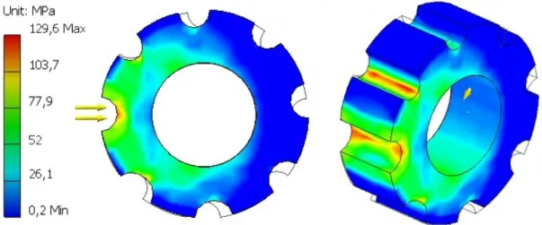
The results relative to the stress analysis are shown in Figure 3.16. The maximum Von Mises Stress is 129.6 MPa, a inferior value comparing to the yield strength of the saintless
Preliminary study of the locking mechanism
Figure 3.16: Slot mechanism - Stress distribution
Figure 3.16 shows that the critical spots of this mechanism are the innermost part of the slots. While the slot where the pawl is inserted (yellow arrows) tends to fracture, the upper slot is compressed due to the applied moment.
The shape of pawl allows for an easier locking and unlocking of the mechanism. Due to the shape of the mechanism, it has the disadvantage of not allowing auto-lock when the pawl is pushed away from the mechanism. When a slot is found, the stays locked to both ways (flexion and extention). In short, this solution is more stronger with an easier transition between phases but needs a faster actuator in order to quickly lock and unlock. Applying 65.4 MPa to the pawl, the results (see Figure 3.17 and appendix C) show that this pawl is suitable to be part of the locking mechanism. The only critical spots (red color) are the lower corners of the mechanism, removing the corners using fillets will result in a higher Von Mises Stress.
Figure 3.17: Pawl 3 - Stress distribution
Preliminary study of the locking mechanism
Figure 3.18: Assembly with slot mechanism
In order to reduce the manufacture costs, a generic mechanism that can be easily modified was considered. The parts of this mechanism were designed with a thickness of 2 mm. In the Figure 3.19 the mechanism is shown.
Figure 3.19: Generic mechanism
This mechanism was not created intending to endure real tests with patients. The purpose of this mechanism is to have a laboratorial prototype. Figure 3.20 shows the different models of this mechanism. The first mechanism (named v1) has a traditional locking system, it is necessary to have the knee fully extended in order to lock, only has one locking position. The second mechanism (named v2) is similar to the first but has two locking positions, which removes the need to be necessary to fully extend the knee and allows a small flexion when the foot touch the ground. The third mechanism (named v3) is similar to the mechanism presented in Figure 3.14, it has several locking positions, this mechanism allows to study the behaviour of a mechanism that has several locking positions. The last mechanism (named v4) allows the extending movement while
Preliminary study of the locking mechanism
Figure 3.20: Generic mechanism - different models
The general dimensions of the mechanisms are shown in Figure 3.21. The dimensions of the different models can be found in the appendix D. Comparing with other mecha-nisms, this mechanism has a smaller thickness. The holes in the top and bottom are to attach the mechanism to the rest of the orthosis.
Figure 3.21: Generic mechanism dimensions
In order to simplify the tests, the mechanisms were divided in two parts, the upper part and the lower part. The upper part is common to all mechanisms, so only one test will be performed. The stress analysis of the upper part can not be known by applying a moment on the mechanism because it will subjected to a force on the pin slot and not to a moment produced by the user, in this case it is needed to calculate the pressure that will be applied to this part. The pin dimensions are: 3 mm Length (L) x 6 mm Width (W) x 5 mm Height (H). The area subjected to the force will be: 2 mm x 5 mm.
Preliminary study of the locking mechanism
Using the dimensions of Figure 3.21 and applying them to equations (3.2) and (3.3), the values obtained are:
F = 6416.7 N p = 641.7 MPa
Figure 3.22: Generic upper part - Stress distribution
Figure 3.22 shows that this mechanism is not appropriate to actual use with patients, due to its small dimensions the mechanism it is subjected to very high pressures. The stress analysis of the lower part can be known by applying a moment of 77 Nm.
Preliminary study of the locking mechanism
Figure 3.23 shows a stress analysis result. This version is subjected to a maximum stress of 662.2 MPa, a value well above of the yield strength of the stainless steel 304. In this mechanism it is possible to observe that the slot widens due to the moment applied. If a moment of 77Nm is applied to the mechanism, it will rupture through the slot down to the shaft of the mechanism.
The second mechanism (see Figure 3.24) has two locking positions, position one and two. In position one the pin stays in the lower position. In position 2 the mechanism stays in the upper part, in this position the mechanism does not need the fully extension of the knee.
(a) Pin in position one (b) Pin in position two
Figure 3.24: Generic lower part v2 - Stress distribution
In the position one (see Figure 3.24a) it can be observed that the maximum Von Mises Stress is 866.5 MPa while in position two (Figure 3.24b) is 757.1 MPa. From this test it is possible to know the most critical positions and it is also possible to compare the results with the mechanism with only one locking position. The v2 mechanism has a Von Mises Stress higher 31% to the most critical position and 14% to the less critical. It is a significative difference between the two versions.
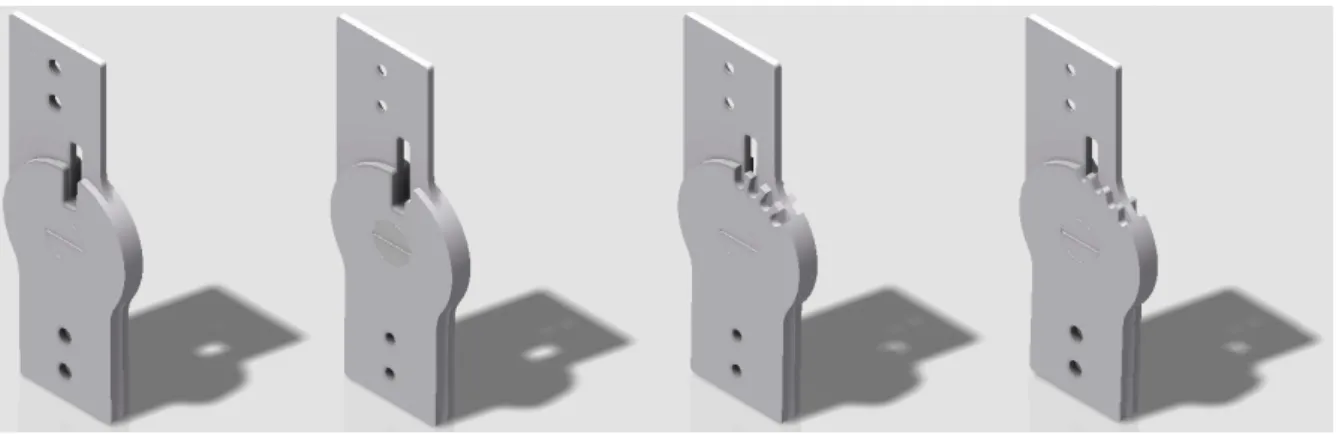
The Figure 3.25 is composed by last two mechanisms, this mechanisms have several locking positions. The v3 mechanism (see Figure 3.25a) is composed by rounded slots while the v4 mechanism (see Figure 3.25b) has locking positions shaped as curved teeth. These mechanisms have a much higher Von Mises Stress comparing to the v1. Instead of 662.2 MPa (v1) the values are 1461 MPa (v3) and 2847 MPa (v4), two and four times
Preliminary study of the locking mechanism
(a) Generic lower part v3 (b) Generic lower part v4
Figure 3.25: Stress distribution
Figure 3.25 shows that both mechanisms lose the shape when applied a moment of 77 Nm. Mechanisms with such shape may be easily damaged, showing that despite having several locking positions the mechanisms are more fragile.
The pin to these four mechanisms is the same, the dimensions of the pin are 3 mm (L) x 6 mm (W) x 5 mm (H). The stress simulation of the pin is presented in Figure 3.26. The simulation shows that this pin made of stainless steel 304 will not support the pressure applied to the mechanism. The area where the pressure is applied made by two parts, so the area has to be multiplied by two, the pressure applied to the mechanism is given by:
F = 6416.7 N p = 6416.7
2(2x5) = 320.8 MPa
In the pin case the shear stress will be double shear stress because the pressure is applied by two elements and not only one. The double shear stress is given as:
τ = V
2A (3.5)
= 6416.7 2(3x5)
Preliminary study of the locking mechanism
Figure 3.26: Locking pin
As shown previously the shear stress is inferior comparing to the maximum Von Mises Stress, the moment of 77 Nm is a very high value that forces the mechanisms to work above the calculated shear stress.
The traditional mechanisms presented in older orthosis (e.g. KAFOs) are similar to the mechanism presented in Figure 3.27. Composed by three parts, two for the main mechanism and the pin that locks the orthosis, these mechanisms were not made to lock and unlock during one gait cycle. They are made to stay locked during the entire gait. The locking is done manually by the user. This mechanism also has a bump which prevents the overextension of the knee.
Figure 3.27: Tradicional mechanism
The computational stress simulation analysis is presented in Figure 3.28. The behaviour is similar to the other mechanisms, the critical spots are located on the same place. Usually the traditional mechanism is made of other metals, with higher yield strength. Normally the mechanisms are subjected to treatments in order to harden. The size of this mechanism is similar to que previous mechanism, has a height of 70 mm, shaft
Preliminary study of the locking mechanism
(a) Upper part (b) Lower part