CELLULAR BEHAVIOUR OF NEURONAL AND
GLIA CELLS IN ELECTRONIC DEVICES
ANA LUÍSA GARCIAS MESTRE
Dissertação de Mestrado em Ciências Biomédicas
Trabalho efetuado sob a orientação de:
Orientador: Prof. Doutor Henrique Leonel Gomes
Coorientadora: Prof. Doutora Inês Araújo
CELLULAR BEHAVIOUR OF NEURONAL AND
GLIA CELLS IN ELECTRONIC DEVICES
ANA LUÍSA GARCIAS MESTRE
Dissertação de Mestrado em Ciências Biomédicas
Trabalho efetuado sob a orientação de:
Orientador: Prof. Doutor Henrique Leonel Gomes
Coorientadora: Prof. Doutora Inês Araújo
Declaração de autoria de trabalho
Declaro ser o autor deste trabalho, que é original e inédito. Autores e trabalhos consultados estão devidamente citados no texto e constam da listagem de referências incluída.
______________________________________________________________________ (Ana Luísa Garcias Mestre)
Copyright © Ana Mestre, 2015
“A Universidade do Algarve tem o direito, perpétuo e sem limites geográficos, de arquivar e publicitar este trabalho através de exemplares impressos reproduzidos em papel ou de forma digital, ou por qualquer outro meio conhecido ou que venha a ser inventado, de o divulgar através de repositórios científicos e de admitir a sua cópia e distribuição com objetivos educacionais ou de investigação, não comerciais, desde que seja dado crédito ao autor e editor”.
Agradecimentos
A Universidade do Algarve tornou-se uma segunda casa por mim, como tal, o meu primeiro agradecimento vai exatamente para este grande centro de partilha de conhecimento que me acompanha há cerca de 8 anos.
A concretização deste trabalho não teria sido possível sem ajuda crucial de um conjunto de pessoas cuja colaboração e apoio foi essencial para a realização deste trabalho final. Por ter estado inserida em dois laboratórios distintos, tenho que agradecer a todos os meus colegas do laboratório de Biologia Molecular da Universidade do Algarve, em especial à Natércia que me acompanhou desde a minha chegada até à data e claro, à Professora Leonor Cancela que me acompanhou também desde o inicio da minha carreira, me proporcionou estar onde estou hoje, assim como por sempre se mostrar disponível para me ajudar e tentando ao máximo que abrisse os meus horizontes.
Queria agradecer aos meus colegas do laboratório de Engenharia Electrónica com quem trabalho diariamente, que se tornaram de certa forma família. Pedro, Joana (Té), Sanaz, Vitaly, Cardoso, Fábinho, Lino e Valdemira não só por toda a ajuda que me deram, mas também pela boa companhia e pelo precioso ambiente que todos juntos conseguimos criar dia após dia.
Não posso deixar de agradecer especialmente ao Pedro, que sem ele esta interface entre a electrónica e a biologia não teria acontecido, ou pelo menos, não desta forma tão benéfica. Quero-lhe agradecer também pela disponibilidade e amizade. Foi muito bom poder contar sempre com ele em qualquer circunstância.
Queria deixar um agradecimento especial também à minha querida amiga e colega Joana Canudo (Té) por tudo. Fez parte da minha vida tanto académica como pessoal e cuja força, empenho e ajuda foi essencial também para a realização deste trabalho.
A todos meus amigos que sem eles também não poderia ser possível terminar este trabalho cujo espaço se torna bastante reduzido para enumerar cada um deles, tendo a certeza que sabem quem são, o meu muitíssimo obrigada por terem feito comigo esta jornada que agora se aproxima do final, sem vocês não teria conseguido.
Aos meus irmãos, Miguel e João, que sem dúvida são grandes responsáveis pela pessoa que me tornei hoje. A amizade e amor incondicional que partilhamos tiveram um papel indispensável para que conseguisse chegar até aqui.
Ao Ricardo que me acompanhou nesta fase tão crucial, stressante e importante da minha vida, por acreditar e me dar força, por me receber sempre com um sorriso rasgado na cara mesmo quando eu sabia que era apenas para me ver sorrir. Por me ter feito sorrir todos estes intensos e prolongados meses o meu muito obrigada.
À minha mãe, sem dúvida! Muito obrigada, muito obrigada as vezes que forem necessárias. A pessoa que me ensinou a ser quem eu sou hoje, cujas palavras de encorajamento foram fundamentais, não esquecendo abraços intensos e fortes foram tão
importantes para que chegasse a esta fase com força e garra de continuar. Quem me ensinou mesmo quando nada parece correr bem o amor incondicional supera tudo. Ao meu pai por estar presente nos momentos importantes da minha vida, pelos ensinamentos, pela generosidade, assim como pelo enorme apoio. Por acreditar que consigo e pelo exemplo de sempre nos deu.
À Professora Inês Araújo por todo o apoio, sabedoria, pela oportunidade, críticas fundamentais, disponibilidade e calma manifestada para me orientar neste percurso tão importante.
Por fim, gostaria de agradecer ao Professor Henrique, não só pela ajuda crucial, como também a amizade que fez questão de partilhar e, não só ao longo deste ano lectivo que passou, pelo qual eu estava destinada a realizar esta dissertação, mas principalmente pelos últimos 3 anos onde se mostrou sempre muito acessível, preocupado e determinado a me ensinar a crescer como pessoa e como profissional. Por todas as portas que me ajudou a abrir e por me ensinar a “abrir a mente” para novos horizontes. Por me mostrar novos caminhos e ensinar-me que desistir não faz parte do vocabulário. Fez-me aprender a lidar com o verdadeiro significado de “stress” e saber que se nos esforçarmos no final vai tudo correr bem. Entre discussões também houve muitas gargalhadas que valeram a pena cada segundo porque acaba por nos conseguir ensinar sempre algo. Por fim, não posso deixar de lhe agradecer por me ter mostrado o verdadeiro significado da palavra líder e de tentar exprimir o orgulho que possuo por os nossos caminhos se terem cruzado.
Gostaria também de agradecer a todo o apoio financeiro de “European Community Seventh Framework Programme” (FP7/2007-2013) através do projeto iONE-FP7 grant agreement n° 280772 e da Fundação para a Ciência e Tecnologia (FCT), através do projeto “Intelligent Cell Surfaces (ICS)”, refº EuroBioSAS/0001/2010.
Resumo
O objetivo desta tese foi estudar o comportamento celular em células neurais em dispositivos electrónicos criando uma ponte entre a electrónica e a biologia. Para este trabalho, células neurais (Neuro-2a) e células da glia (C6) foram cultivadas numa diversidade de componentes electrónicos. Um grande número de dispositivos protótipos foram fabricados e optimizados para interagir com diferentes tipos de células. O tempo de vida, a sensibilidade do componente e o desempenho global foram também avaliados. Foram utilizadas técnicas elétricas de forma a monitorizar as células in vitro, como medições da impedância eléctrica de forma a adquirir informação acerca da adesão celular e viabilidade.
As experiências realizadas forneceram conhecimentos fundamentais: como medir sinais celulares eléctricos utilizado bioelectrónica e também como desenvolver novos transdutores com aplicação nas ciências vivas. Também surgiram aplicações interessantes aplicadas ao mesmo ramo, como é o caso de criar uma plataforma de rastreio de drogas.
Por fim, foi também possível observar sinais quase periódicos que nós supomos tratarem-se de ondas de cálcio intracelulares. Com esta tese, foi possível optimizar materiais e dispositivos para fabricar dispositivos electrónicos capazes de adquirir biosinais extracelulares muito fracos.
Este trabalho está integrado no Projecto Europeu iONE-FP7[1] cujo objetivo é criar um componente para reparar lesões na medula espinhal.
O componente dá-se pelo nome de “Active Multifunctional Implantable Device” - AMID. O AMID é fabricado numa estrutura biocompatível e biodegradável. O objetivo do grupo de investigação da Universidade do Algarve é desenvolver e optimizar componentes individuais antes de serem incorporados no AMID.
Lesão na medula espinhal é uma doença neurodegenerativa que afecta aproximadamente 4 milhões de pessoas em todo o mundo. Esta doença é caracterizada pela desconexão dos axónios, perda de neurónios e de células da glia e desmielinização associada a um processo degenerativo de inflamação secundária relacionado com extensão variável da área lesionada e, como tal, encontra-se relacionada também com diferentes défices funcionais.
Palavras-chave: Componente electrónico Implantável, Cultura de células, Células C6,
Abstract
The aim of this thesis was to study the cellular behaviour of neural cells in electronic devices by creating a bridge between electronics and biology. With this purpose in mind, neuronal cells (Neuro-2a) and glioma C6 cells were cultured in a diversity of electronic devices. A large number of prototypes devices were fabricated and optimized to interact with different types of cells. The lifetime, the sensitivity of the device, and the overall performance were assessed. Electrical techniques were used to monitor cells in vitro, such as impedance measurements of weak signal to acquire information about cell adhesion and viability.
The experiments performed were fundamental to understand how to measure cellular electrical signals using bioelectronics and how to develop new transducers with applications in life sciences. Interesting side-ways applications have emerged, for instance, for drug screening platforms.
Finally, it was also possible to observe “quasi-periodic” signals that we advance to be intracellular calcium waves, based on electrical measurements. With this thesis, it was possible to optimize materials and devices to fabricate electronic devices capable to perform extracellular recording of ultra-weak bio signals.
This work was integrated in the iONE-FP7 Project[1], whose objective was to create a
device to repair Spinal Cord Injury. The device is called AMID, an Active Multifunctional Implantable Device. The AMID is fabricated in a biocompatible and
biodegradable scaffold. The aim of the research group based at the University of the Algarve is to develop and optimize the individual devices before they are incorporated into the AMID.
Spinal cord injury is a neurodegenerative disease that affects approximately 4 million people worldwide. It is characterized by disconnection of axons, loss of neurons and glia and demyelination associated with a secondary inflammatory degenerative process which leads to variable extension of the lesion area, and consequently, to different functional deficits.
[1]http://ione-fp7.eu/consortium/
Keywords: Implantable device, cell culture, C6 cells, Neuro-2a cells, impedance, drug
Results published and submitted for publications
Manuscripts submitted
Henrique L. Gomes, Maria C. R. Medeiros, Ana Mestre, Joana Canudo, Inês M. Araújo, M. L. Cancela, Volker Mailänder, Melanie Dröge, Dago M. de Leeuw, Fabio Biscarini, Leonid Schneider, Paulo R. F. Rocha, “Electrical Recording And Capacitive Stimulation of Quasi- Periodic Spikes in C6 Glioma Cell Populations”, Open
Biology.
Oral communications
Pedro C. Inacio, Sanaz Asgarifar, Ana G. Mestre, Joana Simões Canudo, Inês M. Araújo, M. L. Cancela, Maria do Carmo Medeiros, Fabio Biscarini, Henrique Leonel Gomes, “Conducting polymer electrodes to measure slow cooperative extracellular
signals”, 2015 MRS Fall Meeting Symposium: CC: Organic Bioelectronics—From
Biosensing Platforms to Implantable Nanodevices, 1st-2nd December, Boston (USA) 2015. (Accepted)
P.C. Inácio, A.G. Mestre, S. Asgarifar, Carmen S.R. Freire, Inês M. Araújo, M. L. Cancela, M.C. Medeiros, F. Biscarini and Henrique L. Gomes, “Extracellular
recordings from cardiomyocytes using polymer electrodes on nanofibrous bacterial cellulose substrates”, NANOMED 2015, 23th-25th November, Manchester (UK) 2015. (Accepted)
Ana G. Mestre Pedro C. Inácio, Inês M. Araújo, M. L. Cancela, Maria C. R. Medeiros,
and Henrique L. Gomes, “Drug screening platform based on extracellular electrical
noise measurements”, NANOMED 2015, 23th -25th November, Manchester (UK) 2015.
(Accepted)
Sanaz Asgarifar , Ana G. Mestre, Pedro Inácio, Inês M. Araújo, M. L. Cancela, J. Bragança, Jérôme Borme, George Machado Jr., Fátima Cerqueira, Pedro Alpuim and Henrique L. Gomes, “Highly sensitive electrochemically gated graphene field-effect
transistor for extracellular cell signal recording”, NANOMED 2015, 23th -25th
November, Manchester (UK) 2015. (Accepted)
M.C. R. Medeiros, Ana G. Mestre, Pedro Inácio, Joana Canudo, Inês M. Araújo, M. L. Cancela, Fabio Biscarini, Henrique L. Gomes, “Ink-jet printed polymer electrodes on
bio-cellulose to record extracellular calcium waves produced by neuronal cell populations in vitro”, E-MRS 2015 Spring Meeting, 11th-15th May, Lille (France) (2015). Best paper award of the symposium
Henrique L. Gomes, Pedro C. Inácio, Ana G. Mestre, Joana Canudo, Inês M. Araújo, M. L. Cancela, Maria C. R. Medeiros and Fabio Biscarini, Semiconducting polymer
micro-electrodes and electrical noise based techniques as a tool to probe living cells
in vitro, MRS, Materials, November 30th-December 5th 2014, Boston, USA.
Ana G. Mestre, Implantable Organic Nanoelectronics for regenerative medicine,
Departamento de Engenharia Electrónica e Informática, DDEI, 18th December 2014, Faro, Portugal.
Pedro C. Inácio, Ana G. Mestre, Joana Canudo, Inês M. Araújo, M. L. Cancela, Luís Alcácer, Maria C. R. Medeiros, Fabio Biscarini and Henrique L. Gomes,
Semi-Conducting Polymer Microelectrodes and Electrical Noise Based Techniques as a Tool to Probe Living Cells in vitro, Workshop Nano2014, Academia das Ciências de
Lisboa, 10th October 2014 Lisboa, Portugal.
Posters
Ana G. Mestre, Pedro Inácio, Joana S. Canudo, Inês M. Araújo, M. L. Cancela, M.
Carmo Medeiros, Henrique L. Gomes, Active Multifunctional Implantable Device
for Regenerative Medicine, TechDays Conference, 17th-18th September 2015, Aveiro, Portugal.
Ana G. Mestre, Pedro Inácio, Joana S. Canudo, Inês M. Araújo, M. L. Cancela, M.
Neuroscience Research, TechDays Conference, 17th-18th September 2015, Aveiro,
Portugal.
Ana G. Mestre, Pedro Inácio, Joana S. Canudo, Inês M. Araújo, M. L. Cancela, M.
Carmo Medeiros, Henrique L. Gomes, Electrical noise as a tool to probe populations
of cells in vitro, 4th International Conference on Bio-Sensing Technology by Elsevier, 10th-13th May 2015, Lisboa, Portugal.
Joana Canudo, Ana G. Mestre, Pedro C. Inácio, Luís Alcácer, Inês M. Araújo, M. L. Cancela, Maria C. R. Medeiros, Fabio Biscarini and Henrique L. Gomes, Cooperative
Bioelectrical Activity On Glioma C6 cells Measured Using Electrical Methods, 4th
International Conference on Bio-Sensing Technology by Elsevier, 10th-13th May 2015, Lisboa, Portugal.
Pedro C. Inácio, Ana G. Mestre, Joana Canudo, Luís Alcácer, Inês M. Araújo, M. L. Cancela, Maria C. R. Medeiros, Fabio Biscarini and Henrique L. Gomes, Ink-jet
Printed Polymer Microelectrodes Arrays to Record Electrophisiological Signals of Neuronal Cells in vitro, 4th International Conference on Bio-Sensing Technology by
Elsevier, 10th-13th May 2015, Lisboa, Portugal.
Ana G. Mestre, Pedro Inácio, Joana S. Canudo, Inês M. Araújo, M. L. Cancela, M.
Carmo Medeiros, Henrique L. Gomes, Presentation of Implantable Organic
Nanoelectronics (iONE) Project, 24º Congresso de comunicações, Centro Cultural de
Belém, CCB, Lisboa, 19th-20th November 2014.
Ana G. Mestre, Pedro Inácio, Joana S. Canudo, Inês M. Araújo, M. L. Cancela, M.
Carmo Medeiros, Henrique L. Gomes, Implantable Organic Nanoelectronics (for
regenerative medicine), Instituto de Telecomunicações, 7th November 2014 Aveiro, Portugal.
Ana G. Mestre, Pedro Inácio, Joana S. Canudo, Inês M. Araújo, M. L. Cancela, M.
Carmo Medeiros, Henrique L. Gomes, Using brain-derived cells to investigate
behaviour with chemical and electrical stimulations, Microbiotech Conference, 6th -8th December 2013, Aveiro, Portugal.
Other dissemination activities
National TV program about science (“Exame Informática”) see links below.
[1] https://www.youtube.com/watch?v=YhwEOdGtSIg
[2] https://www.facebook.com/video.php?v=834544639922700&set=vb.190354481008389&type=2&theater [3] Feature article “Um implante pode tratar lesões na medulla espinal?”, in the national newspaper “Jornal de Negocios”, November (2014).
Index
Agradecimentos --- iv
Resumo --- vi
Abstract --- viii
Results published and submitted for publications --- ix
MANUSCRIPTS SUBMITTED --- IX ORAL COMMUNICATIONS --- IX POSTERS --- X Index --- xiii
Index of Figures --- xvi
Index of Tables --- xix
Abbreviations --- xx
CHAPTER 1 --- 1
INTRODUCTION --- 1
1.1 IMPLANTABLE DEVICES TO REPAIR SPINAL CORD INJURY --- 2
1.2 THERAPEUTICAL APPROACHES OF SCI --- 5
1.3 OBJECTIVE --- 9
CHAPTER 2 --- 10
METHODS AND TECHNIQUES --- 10
2.1 DEVICE LAYOUT AND STRUCTURE --- 11
2.2 DEVICE HOLDERS --- 14
2.3 POLYMER ELECTRODES --- 15
2.4 ELECTRONIC ACQUISITION SYSTEM --- 16
2.6 STERILIZATION AND COATING PROCEDURES --- 18
2.7 CELL CULTURES --- 18
2.7.1 Neuro-2a cells --- 19
2.7.2 C6 cells --- 20
CHAPTER 3 --- 21
CELL ADHESION AND DEVICE STABILITY --- 21
3.1 INTRODUCTION --- 22
3.2 EXPERIMENTAL --- 24
3.3 RESULTS --- 25
3.3.1 The drift of the impedance with time --- 26
3.3.2 The effect of the cell density on the impedance --- 32
3.3.3 Changes on the impedance upon chemical stimulation --- 33
3.4 CONCLUSIONS --- 35
CHAPTER 4 --- 36
DRUG-SCREENING PLATFORM --- 36
4.1 INTRODUCTION --- 37
4.2 ELECTRODE NOISE ANALYSIS --- 37
4.3 RESULTS --- 39
4.4 DISCUSSION AND CONCLUSION --- 41
CHAPTER 5 --- 42
QUASI-PERIODIC SPIKES IN GLIOMA CELLS --- 42
5.1 INTRODUCTION --- 43 5.2 RESULTS --- 45 5.3 DISCUSSION --- 52 5.4 CONCLUSIONS --- 54 CHAPTER 6 --- 55 CONCLUSIONS --- 55
6.1 CONCLUSIONS --- 56
6.2 SUGGESTIONS FOR FURTHER WORK --- 57
6.2.1 Observation of low frequency and ultra weak extracellular signals --- 57
6.2.2 Drug screening platform --- 57
6.2.3 Prosthetic and electroceutical devices. --- 57
6.2.4 Implantable devices --- 58
CHAPTER 7 --- 59
Index of Figures
Fig. 1.1 —Schematic demonstration of implantation in the injury place. The implant will be in contact with the spinal cord injury. The sensing area refers to the local where the device will be placed. ... 3 Fig. 1.2 — Prototype of the iONE project device called “AMID” - Active Multifunctional Implantable Device. ... 4 Fig. 1.3 — Photograph of the implantable device produced by the iONE project. ... 5 Fig. 2.1 — Electrode designs used in this thesis. (a) Gold microelectrode arrays on top of thermal oxidized silicon wafers, (b) Commercial available electrodes on plastic substrates (PET), (c) Electrode geometries using printed polymers on bacterial cellulose substrate, (d) Electrode geometries using printed polymers on glass substrate. ... 11 Fig. 2.2 — Electrode dimensions and surface morphologies. (a) Photograph of the C6 cells on top of glass substrates with gold electrodes. The darker regions are the gold regions (transparent substrate) (b) Photograph of the ink-jet printed PEDOT fingers on glass, (c) Typical bacterial cellulose substrate with ink-jet printed PEDOT electrodes and (d) Atomic Force Microscopy (AFM) photograph of the bacterial cellulose nanofibrous structure. ... 12 Fig. 2.3 — (a) and (b) Individual silicon wafer with 4 microelectrode arrays, (c) Detailed view of the gold electrode fingers and (d) Cross sectional view of the device structure with the electrolyte solution, showing the three terminals, source, drain and gate... 13 Fig. 2.4 — Gold microelectrodes on plastic provided by IBIDI (http://ibidi.com/)... 13 Fig. 2.5 — Schematics of a Petri dish and Chip Holder (PDCH). (a) Schematic representation of the PDCH, (b) Photograph of a device holder mounted and (c) Schematics representation. ... 14 Fig. 2.6 — Typical sensing device using bacterial cellulose as a substrate mounted in a Petri dish. ... 15 Fig. 2.7 — Experimental setup. Equipment used to record bioelectrical signals. The equipment is inside an iron-based Faraday cage in order to remove interferences. 16 Fig. 2.8 — Electrode design showing the depth (D), length (L) and width (W). ... 17 Fig. 2.9 — Neuro2a cells in culture. Scale bar: 200 m. ... 19 Fig. 2.10 — C6 cells in culture. Scale bar: 200 m. ... 20 Fig. 3.1 — Schematic representation of the Helmholtz layer established at the eletcrode/electrolyte interface. This charged layer has a capacitance and is convenientely described by a capacitor. A more accurate representation may use two capacitors arranged in series, one to take into account the layer near to the surface (Cads) in series with a more extended layer Cdiff. ... 22
Fig. 3.2 — The Helmholtz capacitive layer established in the metal/electrolyte interface can be electrically simulated by a double RC circuit show on (b). The ideal frequency response of this circuit is shown on (c) for the capacitance and loss (1/(R). ... 23 Fig. 3.3 — Schematic representation of how the electric field lines flow amid the gap junctions between cells. This is valid for ac signals in the frequency range of a few kHz. The pink lines represent the high frequency signals flowing trough the gap junctions. The green lines represent the low frequency field flowing trough the membrane. ... 24
Fig. 3.4 — Schematic diagram of the sensing device structure and connections to the impedance analyzer. The labels of the electrode’s physical dimensions are also show. Devices’ dimensions are described in Table 2.1 (chapter 2). ... 25 Fig. 3.5 — The frequency dependence of the capacitance for the different electrodes used. The continuous blue and green line are extrapolations to low frequencies, whereas the red line represents the simulation to a perfect Maxwell-Wagner relaxation using a double-RC network. ... 26 Fig. 3.6 — Temporal evolution of the frequency dependence and time dependence of the capacitance and loss. ... 27 Fig. 3.7 — The time dependence of the impedance spectrum for two cell culture mediums: (a) for the Krebs medium and (b) for the F-12K medium. ... 28 Fig. 3.8 — Time dependence and time evolution of the capacitance spectrum for Krebs medium and F-12K medium. (a) Time dependence for both mediums. (b) The capacitance evolution measured at a single frequency of 100Hz. ... 30 Fig. 3.9 — The time dependence and time evolution of the loss peak for a gold electrode immersed in two types of mediums: Krebs medium and F-12K medium. (a) Time dependence for both mediums. (b) The capacitance evolution measured at a single frequency of 100Hz. ... 31 Fig. 3.10 — The frequency response of the capacitance and loss for two cell densities. The electrodes used are inter-digitated gold electrodes on silicon (Philips device) coated with C6 cells. ... 32 Fig. 3.11 — The effect of cell density on the time dependence of the impedance (a) 178200 cells and (b) 1803375 cells. The impedance was measured on a Philips device using C6 cells. ... 33 Fig. 3.12 — Correlation between impedance and electrical noise data. (a) Fluctuations in the impedance occur simultaneously at the onset of electrical activity. These data were recorded using C6 cells. ... 34 Fig. 3.13 — The effect on the capacitance and loss with a 8.3mM solution of lactic acid added to the cell culture medium. ... 34 Fig. 4.1 — The noise spectral density of two types of measuring electrodes, gold and printed PEDOT:PSS electrodes on glass. One of the insets shows the equivalent RC network. The other inset shows an expanded view of the PEDOT:PSS noise specral density. ... 39 Fig. 4.2 — Time trace of the current recorded using gold microelectrode arrays and C6 cells. Bursts of noise are plainly visible in a noise floor of 4pA (peak-to peak). ... 40 Fig. 4.3 — Time trace of the current measured in C6 cells before and after the exposure to a solution of tetrodotoxin. The sensing electrodes are gold microelectrodes as described in Chapter 2. ... 40 Fig. 4.4 — Chemical induced activity in Neuro-2a cells. Adding a solution 30mM of KCl to the cell culture medium carried out the stimulus. After the addition of a KCl solution the noise increased dramatically. ... 41 Fig. 5.1 — Frequency dependence of the capacitance (C) and loss (1/Rω). As the cells adhere to the sensing electrodes, the Maxwell-Wagner relaxation moves to lower frequencies. The inset shows a time trace of the noise current fluctuations when the C6 cells are resting and adherent to the microelectrodes. ... 46 Fig. 5.2 — Stimulated cell activity. (a) Time dependence of the current recorded after the application of a train of voltage pulses (5 V, 200μs for 2 minutes), (b) a quasi- periodic signal with a frequency approximately of 0.2Hz. Electrical measurements were carried out using the floating differential amplifier. (c) Consecutive traces with individual lengths of 60s recorded from the bottom to the top. Trace (A)
shows a pure thermal noise. Trace (B) is recorder after capacitive stimulation; small and non- periodic burst of activity are observed. Later in trace (C) the burst increase in amplitude and evolve to a perfect periodic activity as shown in traces (D) and (E). The signals can be stopped upon the addition of ethylenediamine tetraacetic acid (EDTA) as shown in trace (G)... 48 Fig. 5.3 — (a) Evolution of the magnitude and frequency of the spikes with time for a spontaneous activity; four distinct periods of activities can be detected. (b) Bursting activity, (c) view of an individual burst and (d) detailed view of quasi-periodic spikes inside the burst. The inter-spike interval is 3.3 s (0.3Hz). (e) Histogram of the inter- spike intervals recorded for the entire burst activity shown in (a). The inter-spike intervals were distributed into time slots with a resolution of 0.33s. The inset shows the histogram of the corresponding frequencies. ... 50 Fig. 5.4 — Kinetics of cell growth (a) and cell metabolism-related pH changes in culture medium (b). 2.3x10⁵ cells were seeded initially in a volume of 200μl.
Average cell vitality was 79% (±12%). Results provided by a partner (Paulo Rocha at Max Planck Institute for Polymer Research). ... 52
Index of Tables
Table 1.1 – SCI repair involving cellular therapy. ... 6 Table 1.2 – SCI repair strategies. For each, the system applied, the SCI model (rodent) and the respective results are shown... 8 Table 2.1 — Standard device dimensions used. ... 17
Abbreviations
AC Alternate Current
AFM Atomic Force Microscopy
AMID Active Multifunctional Implantable Device ASIC Acid Sensing Ion Channel
ATCC American Type Culture Collection
C Capacitance
CNS Central Nervous System
DC Direct Current
DMEM Dulbecco’s Modified Eagle Medium DMP Dimatix Material Printer
EDTA Ethylenediamine Tetraacetic Acid
f Frequency
FBS Foetal Bovine Serum
FCT Portuguese Foundation for Science FET Field-Effect Transistor
G Conductance
GABA Gamma-aminobutyric acid GluR Glutamate receptors ICW Intercellular Calcium Wave
iONE Implantable Organic Nanoelectronics
k Boltzmann Constant
MEA Micro Electrode Array
MISFET Metal-Insulator-Semiconductor Field-Effect Transistor PDCH Petri dish and Chip Holder
PEDOT Poly(3,4-ethylenedioxythiophene)
PET Polyethelene Erephthalate PNS Peripheral Nervous System PSD Power Spectral Density PSS Poly(styrene sulfonic acid)
RC Resistor-Capacitance
SCI Spinal Cord Injury
T Temperature
TTX Tetrodotoxin
CHAPTER 1
1.1 Implantable devices to repair spinal cord injury
The research that constitutes the core subject of this thesis was developed in the context of a project entitled “Implantable Organic Nanoelectronics (i-ONE)”. The iONE Project aims to develop a new tool for treating spinal cord injury (SCI). SCI is a neurodegenerative disease of the central nervous system (CNS) affecting an estimated 2.5 million people worldwide, with more than 130,000 new cases reported each year. SCI has a significant impact on quality of life, life expectancy and represents a significant economic burden, with considerable costs associated with primary care, sometimes resulting in loss of individual income. To date, no treatment for SCI has allowed for a full recovery of lost motility, sensibility and function.
The main rational underpinning the project is to develop a multifunctional device prototyped on the patient, implanted at the SCI site, operated from the outside for the duration of the therapy, that will bio-degrade itself afterwards. The device will allow one to identify a suitable combination of stimuli to evoke and modulate the signal across the region of the injury. It will also enable the controlled delivery of stem cells to the SCI site and stimulate their differentiation into neurons. Its lifetime will be tailored to the duration of the therapy to reduce the risk of a host versus graft immune response. The device must be suitable as to allow neurosurgery to be performed on individuals. The implant is minimally invasive due to its miniaturization, mechanical compliance, conformal adhesion, choice of biodegradable materials and scaffold. Therefor, the envisioned device is a versatile tool for in-situ functionality.
The transplantation of stem cells or stem cell-derived progenitors represents a promising therapeutic solution for repairing the damaged nervous system. These cells should be able to develop into functional neurons in order to integrate synaptically into the host brain circuitry. This approach requires implantable multifunctional devices suitable for engrafting neural stem/precursors cells. Devices should have long-term stability associated to high biocompatibility and safety, and reduced risk of a host versus graft immune response. Since stem cell commitment is governed by a combination of top-electro-chemical stimuli, the device should be able to mimic the local microenvironment for stem cell differentiation. This may require a possibility to perform local stimulation with electric fields, local delivery of growth factors, neurotransmitters, and drugs. The integration of highly sensitive transducers in the
implanted device would allow for monitoring the status of the regenerating nerve cells and controlling the auto-immune inflammatory response in vivo as demonstrated in Fig.1.1.
Fig. 1.1 —Schematic demonstration of implantation in the injury place. The implant will be in contact with the spinal cord injury. The sensing area refers to the local where
the device will be placed.
Although the device is targeted to the Central Nervous System in terms of design, materials and prototyping approach, the concept can be extended to other organs/tissues and environments, also in vitro, where stem cells need to be precisely stimulated. The implanted device will be used for monitoring neuronal transmission at the injury site, thus enabling the follow-up of the therapy in the patient.
In order to promote regeneration, a combination of electrical, chemical and electrochemical stimuli can be used to induce residual plasticity and neural stem cells can be locally delivered and differentiated into neurons. The device provides therapeutic treatment of the inflammation evoked by the spinal cord injury and the following
necrosis.
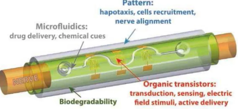
The implant is bendable in a cylinder like shape. It integrates an array of three type of different devices; as is shown in Fig.1.2 the device is composed of: (i) organic transistors which can supply electric and electro-chemical stimuli to the neurons, (ii) electrodes that can monitor the neurons response; (iii) microfluidics actuated by organic electronics that pump and control the delivery of anti-inflammatory drugs, differentiation and growth factors, and neurotransmitters. Individual devices were studied and optimized at different nodes of the iONE consortium. The role of the Algarve team is to develop a transducer capable of recording signals from the cells and also to stimulate the cells using electrical signals. Part of this work is reported in this thesis.
Fig. 1.2 — Prototype of the iONE project device called “AMID” - Active Multifunctional Implantable Device.
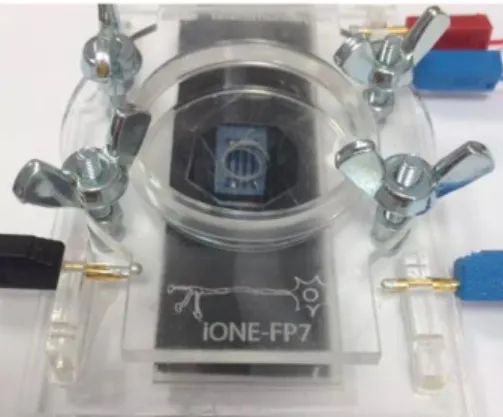
During the project the individual devices were optimized and integrated into a final AMID device. Fig. 1.3 shows a photograph of the implantable device.
Fig. 1.3 — Photograph of the implantable device produced by the iONE project. The complexity of both the medical problem and the implant requires the integration of multidisciplinary expertise in bioelectronics, neurology, stem cells, imaging diagnostics, anatomy, experimental neuroimaging, electronic and software engineering,
In this context, the work carried out is relevant to tissue engineering and regenerative medicine. The multi-functionality of the device preludes its potential use in cell therapy and bio-artificial organs due to its capability to monitor/react in real time as is necessary.
1.2 Therapeutical approaches of SCI
There are few examples of SCI therapies based on stem cells that have been approved by regulatory bodies, including the EMA in Europe and FDA in USA. The main difficulty encountered in these therapies concerns the poor control of (1) the cellular sensing and response to the microenvironment, (2) directed cell migration, (3) some key decision-making processes that include proliferation/activation/death, and (4) the precise dynamic control over distribution, level and duration of action. Combining stem cell transplants with the delivery of small molecules such as neurotransmitters and anti-inflammatory drugs to the SCI site coupled with rehabilitation practices for several days is a key technological need that has yet to be met [1], [2].
In spite of the many evidences provided by animal models that decompression in the local of injury increases functional recovery and minimizes the secondary injury in this disorder, there are some interventions that can be done based on a number of approaches, such as surgical (decompression), pharmacological (administration of methylprednisolone) and electrophysiological (by the stimulation of a specific point). New approaches for SCI repair that already have been tested include cell therapy with neural stem cells, mesenchymal stem cells, olfactory ensheathing cells, Schwann cells, activated macrophages, embryonic stem cells, but as expected these strategies, whose main features and respective outcomes are detailed in Table 1.1, minimized but did not repair the injury [3].
Table 1.1 – SCI repair involving cellular therapy.
System
Outcome
Neural stem cells
Able to differentiate into neurons, oligodendrocytes and astrocytes; concerning SCI, they are used to replace the loss of tissue and to foster trophic support for the survival neural tissue. It was tested in vitro and in
vivo (adult rats) [4], [5].
Mesenchymal stem cells
Used for regenerative applications, these cells are easy to isolate and expand; they also have anti-inflammatory and anti-immunosuppressant effect and do not form tumours. They are derived from the bone marrow. In traumatic SCI models experimental studies led to some motor improvements. The cells were injected into or next to the SCI site, but they can be delivered intrathecally or intravenously [6]–[12].
Olfactory ensheathing cells
Play an important role in the lifelong neural regeneration capacity of olfactory neurons in adult rats. They can create a permissive microenvironment for axonal regeneration across the injury site in humans [13]–[15].
Schwann cells Promote axonal regeneration and myelination in adult rat thoracic spinal cord [16], [17].
Activated macrophages
Capable of producing growth factors and scavenging neurotoxins such as excessive quantities of glutamate. Sufficiently activated macrophages can contribute positively to the homeostasis of the central nervous system. In preclinical studies, recovery of hind-limb function has been reported after transection and transplantation of macrophages that had been previously activated with PNS tissue [18]–[20].
Embryonic stem cells
Indefinite ability of self-renew and they can differentiate into cells from all three germ layers. In order to obtain a desirable cell population, in vitro was performed pre-differentiation mouse ES cells in neurons and olidendrocytes. Both resulted in remyelination and functional recovery in contusion SCI animals [21]–[23].
Besides cells therapy, both molecular therapy and combinatorial therapies were tested. Tissue engineering holds great promise for SCI because of the possibility of tissue regeneration (including bone, cartilage, neurons and muscle). Needing to include a specific set of characteristics, a scaffold created for tissue engineering must (i) be biocompatible; (ii) have desirable physical characteristics (high porosity, large surface area), (iii) be biodegradable and (iv) have desirable surface properties (to deliver drugs) [3], [24], [25]. Tissue engineering strategies to repair SCI have been energetically tested in the past years and are summarized in Table 1.2.
Table 1.2 – SCI repair strategies. For each, the system applied, the SCI model (rodent) and the respective results are shown.
System
Outcome
Implantation of synthetic non-degradable hydrogel PHPMA
(poly-(2-hydroxypropyl)-methacrylamine) modified with the amino acid sequence RGD
Functional recovery; regeneration of sensory axons; decrease in scar tissue formation; little invasion of regenerating axons into the channels; studied in chronic transection SCI model [26][26]–[29].
Implantation of synthetic polymers with the biomaterial PEG (polyethylene glycol)
Repairs cell membrane breaches; decrease excitotoxicity; inhibit the production of free radicals; decrease lesion volume; attenuate in macrophage response; improved motor outcomes [30], [31].
Implantation of PEG-PLA (PEG-poly-lactic acid) hydrogel containing NT3
Improves BBB score and ladder walker performance; increases the number of axons [32].
Combination of NSCs and synthetic PLGA (poly-lactic-co-glycolic acid) scaffolds with aligned porosity
Reduces scar formation; improves functional recovery [33].
Synthetic matrix composed by peptide amphiphile (PA)
Improves motor function; reduces astrogliosis; decreases cell death; promotes regeneration of ascending and descending track axons through the local of injury; descending track axons through the lesion site [34]. Collagen Increases the number of axons either when used alone in
combination with NT3 or even when used to fill PHEMA-MMA and chitosan tubes; implantation in SCI rodents to fill the gap in transection models of SCI [27], [35]–[37].
The use of Matrigel and contains several bioactive molecules, such as laminin, fibronectin, and proteoglycans, with laminin predominating
NSCs differentiation into neurons and oligodendrocytes; increases sensory axonal regeneration; cell infiltration through the gel; increases angiogenesis and SCs survival; facilitates intralesional axon growth; promotes functional recovery; injected in a contusion rat model of SCI [38], [39].
Fibrin, is probably the most extensively used hydrogel in SCI.
Releases NT3 after degradation by invading cells; increases nervous cells infiltration; diminished the glial scar. Moreover, the use of fibrin in combination with cAMP and pre-differentiated NSCs resulted in extensive axonal regeneration into the injury site of fully transected rats; improved functional recovery after 6 weeks [40]–[44].
Agarose and Alginate Decrease of the lesion volume; Macrophages invasion; proteoglycans content; oxidative stress; production of BDNF encapsulated in alginate micro-capsules, could be delivery to the spinal cord without the need for immunosuppression; growth of regenerating axons; improved the function of affected limbs; injected in a hemisection rat model of SCI [45], [46].
3D biodegradables structures based on rapid prototyped starch poly-caprolactone scaffolds
Improvements in distance traveled and rearing activity in rats with SCI [3].
1.3 Objective
The aim of this thesis was to study the cellular behaviour of neural cells in electronic devices by creating a bridge between electronics and biology. With this purpose in mind, neural cells, Neuro2a cells (neuroblastoma) and C6 cells (glioma) that were cultured in a diversity of electronic devices comprising different characteristics, such as the material of the substrate (Polyethelene Erephthalate (PET), SiO2, Titanium,
Bacterial Cellulose) and the material of the electrodes (Gold and poly (3,4-ethylenedioxythiophene) polystyrene sulfonate (PEDOT:PSS)). For the iONE-FP7 Project, our group in University of Algarve aimed at optimising the AMID by measuring the neural cells in the devices provided by the partners in the iONE –FP7 consortium.
Within this framework, the role of the UAlg team was to develop an electronic transducer to monitor living cells and their response to a number of electrical and chemical stimuli in real time. These cell cultures are adherent and were used as prototype cells to test the transducer and the electrical addressing techniques. These cells were electrically and chemically stimulated and were monitored using a set of electrical techniques, which includes low-frequency impedance and electrical noise. The major achievements of this work are outlined below.
This thesis is organized as follows: Chapter 1 contains the introductory remarks explaining the context of the work and reviewing the state-of-art; Chapter 2 outlines the experimental techniques and describes in details the cell cultures utilised; in turn, Chapter 3 focus on the use of small-signal impedance methods to gain information about cell adhesion and viability; Chapter 4 describes the electrical measuring method used to detect cell electrical activity and presents the possibility of using electrical noise as a drug-screening platform; Chapter 5 follows by presenting the observation of intercellular calcium waves electrically; finally, the major conclusions of this thesis are summarized in Chapter 6, that also contains a list of recommendations for further work and research.
CHAPTER 2
Methods and Techniques
This chapter describes the experimental methods, the cultured cells and the geometry of the electrodes arrays used. The electronic instrumentation used to record extracellular signals is also outlined.
2.1 Device layout and structure
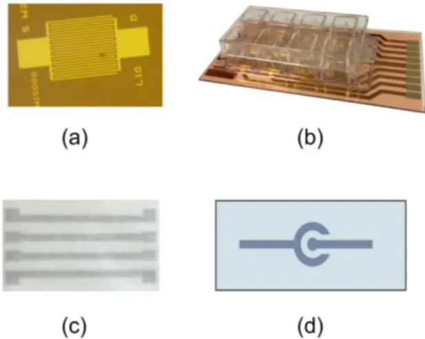
This section gives an overview of the experimental set-up developed for performing in-vitro measurements. The main components of the in-vitro experiments are: (i) the device; (ii) the “device holder”, which allows making electrical connections between the device and the instrumentation, and confines the cell medium on the active surface of the sensor device; (iii) the incubator and finally, (iv) the amplifier and the spectrum analyzer. The devices used for measurements consisted of simple microelectrode arrays fabricated using gold or ink-jet printed polymers on glass or on bacterial cellulose. Some of the designs used are shown in Fig. 2.1. Typical device dimensions and surface morphologies are shown in Fig. 2.2.
Fig. 2.1 — Electrode designs used in this thesis. (a) Gold microelectrode arrays on top of thermal oxidized silicon wafers, (b) Commercial available electrodes on plastic substrates (PET), (c) Electrode geometries using printed polymers on bacterial cellulose substrate, (d) Electrode geometries using printed polymers on glass substrate.
Fig. 2.2 — Electrode dimensions and surface morphologies. (a) Photograph of the C6 cells on top of glass substrates with gold electrodes. The darker regions are the gold regions (transparent substrate) (b) Photograph of the ink-jet printed PEDOT fingers on glass, (c) Typical bacterial cellulose substrate with ink-jet printed PEDOT electrodes and (d) Atomic Force Microscopy (AFM) photograph of the bacterial cellulose nanofibrous structure.
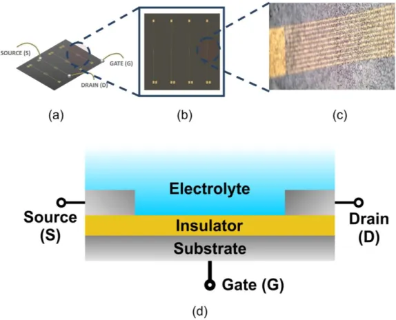
Gold interdigitated electrodes on the top of oxidized silicon wafers were explored as transducers to electrically stimulate the cells. Each wafer has 4 devices with different inter-electrode distances. A typical layout is shown in Fig. 2.3. The silicon wafer on the top surface is thermally oxidized (SiO2). The bidirectional transducer (Fig.2.3) is an
interdigitated microelectrode array (Philips Innovation Services, Eindhoven, The Netherlands) fabricated on thermally oxidised Si wafers 150mm in diameter. The oxide is 200nm thick and can be used to couple alternative current (AC) signals to the cells. The Au electrode arrays were 10000μm long and separated apart by 20μm.
The thin insulating top layer can be used as a capacitive layer to electrically stimulate the cells. The device resembles a metal-insulator-semiconductor (MIS) structure. Voltage pulses can be applied to the gate voltage and capacitive coupled into the electrolyte solution and to the cells.
Fig. 2.3 — (a) and (b) Individual silicon wafer with 4 microelectrode arrays, (c) Detailed view of the gold electrode fingers and (d) Cross sectional view of the device structure with the electrolyte solution, showing the three terminals, source, drain and gate.
Moreover, commercially available electrodes with built-in vessels to hold the cell cultures were also used. These devices were supplied by the company IBIDI (http://ibidi.com/). These electrodes were made of semi transparent gold on a plastic substrate (PET). A detailed view of the electrodes is shown in Fig. 2.4.
2.2 Device holders
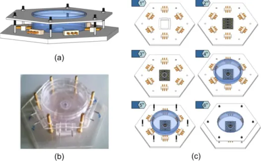
The device holders are supports designed to hold a variety of sensing devices and can be plugged into several measuring systems. Furthermore, they allow keeping cell cultures alive over extended periods of time (weeks) due to a sufficiently large cell reservoir (>200L), and since they were designed in transparent materials, visual inspection is also possible.
The Petri dish and Chip Holder (PDCH) (see Fig. 2.5 developed by UAlg) is the proposed device to perform assays of cells culture in vitro. The assembled prototype was fabricated using transparent extruded acrylic. It makes use of a standard commercial available Petri dish (4cm in diameter). The sensing devices were glued onto commercial available glass slides. Electrical contacts were sealed from electrolyte using commercial available biocompatible o-rings. The Petri dish has the capacity of 2mL of cell culture medium. The entire system can be used in inverted microscopes. Fig. 2.5 shows the different steps to assemble the chip holder. Fig. 2.6 shows a typical sensing device using bacterial cellulose as a substrate mounted in a Petri dish. Bacterial cellulose is a biomaterial with physical and mechanical properties of interest that can be used both as a substrate and in addressing the use of such membranes for drug loading and controlled release.
Fig. 2.5 — Schematics of a Petri dish and Chip Holder (PDCH). (a) Schematic representation of the PDCH, (b) Photograph of a device holder mounted and (c)
Fig. 2.6 — Typical sensing device using bacterial cellulose as a substrate mounted in a Petri dish.
Cellulose substrates were produced by a bacteria from the Gluconacetobacter genus that produces an extremely variety of bacterial cellulose, in the form of a highly swollen membrane, with around 99% water, on the culture medium surface [47].
2.3 Polymer electrodes
Ink-jet printing is a method of deposition of functional materials. Some examples of functional materials that can be ink-jet printed include metal inks, conductive and semi-conductive polymers, proteins and nanoparticles.
Inkjet printing is a cost-effective and flexible method used in several research areas such as chemical, mechanical, optical researches and in a wide range of applications like electronics, optoelectronics and displays [48].
Polymer electrodes, poly (3,4-ethylenedioxythiophene) polystyrene sulfonate (PEDOT:PSS), were fabricated by inkjet-printing. Printing was performed using a Fujifilm Dimatix Material Printer (DMP) 2831, with a DMC-11610 cartridge. This cartridge contains 16 nozzles, which generates 10l drops of ink. For all electrodes, an aqueous dispersion of PEDOT:PSS was employed, which after solvent drying and thermal annealing, formed into a continuous and transparent conducting film. Before filling the cartridge, PEDOT:PSS based ink was subjected to a ultrasonic bath for 15 min.
For glass devices during printing, substrates were kept at a constant temperature of 55˚C to help fast solvent evaporation and bacterial cellulose devices are kept at room temperature. For substrates, glass and bacterial cellulose, electrodes were fabricated with 8 printed layers with a drop spacing of 30µm. In order to minimize ink spreading
on the substrate, a waiting period of 30 minutes between each layer was observed. After printing, samples were annealed on a hot plate at 60˚C for 8h. After annealing, the devices were immersed in an ethyleneglycol solution. Finally, the devices were dried in a vacuum oven at 60˚C for 12h and bacterial cellulose substrate samples were annealed on a hot plate at 40ºC for 8h.
An approach using PEDOT:PSS electrodes on both substrates that are particularly suited to measure cell populations that engage into cooperative activity was also used. The relevant characteristics of this kind of device are their flexibility and biocompatibility.
2.4 Electronic acquisition system
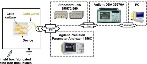
The electrical activity of the cells was recorded using the experimental set-up described in Fig. 2.7. This set-up is comprised of an Agilent 35670A Dynamic Signal Analyzer, a low-noise current pre-amplifier Stanford Research SR 570 or, alternatively, a low noise voltage amplifier the SRS 560. Electrical excitation was applied using a pulse generator 32220A. The sensing devices were kept inside the incubator. The entire system was operating inside a large iron box with an electrical ground to shield external sources of electrical noise and interference (see Fig. 2.7).
Fig. 2.7 — Experimental setup. Equipment used to record bioelectrical signals. The equipment is inside an iron-based Faraday cage in order to remove interferences.
2.5 Electrode dimensions
The sensing devices use two parallel electrodes of depth, D, separated by a channel length L and width, W. The coplanar electrode design is show in Fig. 2.8. The figure also represents the labels corresponding to the electrode dimensions. Standard electrode dimensions are shown in table 2.1.
Fig. 2.8 — Electrode design showing the depth (D), length (L) and width (W). Table 2.1 — Standard device dimensions used.
Device
Width
(µm)
D
GAP(µm)
Length
(µm)
IBIDI – 8WCP (GOLD/P3MT electrodes) 8 640 215 IBIDI – 8WCP PET (GOLD/P3MT electrodes) 3520 100 325 PHILIPS – 4 MISFET (GOLD/P3MT electrodes) 1000 5 10 Glass + PLGA (PEDOT electrodes) 7000 500 600 Bacterial cellulose + PLGA(PEDOT electrodes) 7000 500 800 Gold electrodes
(Glass + TiO2) 3670 340 610
Gold electrodes
2.6 Sterilization and coating procedures
Prior to cell deposition the devices were sterilized (utilising an ultraviolet light) and coated with poly-L-lysine 0.01% provided by Sigma-Aldrich in order to promote cell adhesion. The surface of the device was washed with sterilized water and after that it was covered with poly-L-lysine for 5 minutes. Finally, the poly-L-lysine was removed and washed again with sterilized water, and the devices were ready to use with cells after 2h.
2.7 Cell cultures
For in vitro measurement protocols several different cell types were tested, namely: (i) Neuro-2a (Mus musculus, Mouse neuroblastoma) and (ii) C6 cells, Rattus norvegicus, (Rat). Cell viability and pH kinetics assay were performed on 96 well plates. The cells were grown in culture plates and then detached, diluted in culture medium to yield cell suspensions with a known cell density and transferred to the sensing devices. An aliquot of 350μL of the cell suspension (concentration≈5.1x10⁶ cells/mL) was transferred to the
well of the sensing device and cells were allowed to settle onto the device for 2h before any measurements were performed.
In case a chemical stimulation is required, a cell culture medium with a defined concentration of the chemical was prepared. This solution was then used to replace the cell culture medium.
The pH on supernatants was measured with Lab850 pH-meter (Schott Instruments). Cell numbers and viability were assessed using a Neubauer chamber-based trypan blue live/dead exclusion assay. The device loaded with the cells was then incubated in a cell incubator (HERACell®150) that was kept clean. The incubator kept the cells under a
humidified atmosphere at 37ºC with 5% CO2. Half of the medium was changed every
4-5 hours.
Regarding the experiments three different types of mediums were used: (i) Krebs medium, (ii) F-12K Nut Mix medium, and (iii) DMEM (1x). Krebs Medium composed by 132mM NaCl, 4mM KCl, 1,4mM MgCl2, 6mM Glucose and 10mM Hepes-Na at a pH of 7.4. The F-12K Nut Mix (1x) composed by Nutrient Mixture supplemented with 15% horse serum, 2.5% foetal bovine serum (FBS) and 1% penicillin and streptomycin
was used for C6 cells. And finally, DMEM (1x), 10% foetal bovine serum (FBS) and 1% of penicillin and streptomycin was used for Neuro-2a cell cultures.
2.7.1 Neuro-2a cells
Neuro-2a cells (American Type Culture Collection, ATCC) were cultured in DMEM (1x), 10% foetal bovine serum (FBS) and 1% of penicillin and streptomycin. The cells were maintained in a humidified atmosphere at 5% of CO2 and 37ºC. The medium was
changed every two days. In Fig. 2.9 is possible to see Neuro-2a cells in culture.
Neuro-2a cells are derived from mouses and the morphology of this kind of cells is neuronal. The cell type is neuroblast. Neuro-2a cells are adherent cells capable of producing action potentials [49].
We applied 5 million cells/mL of Neuro-2a cells on the device and incubated them at 37ºC and 5% CO2 for 2hours previous to the experiments.
2.7.2 C6 cells
Rat glioma C6 cells (American Type Culture Collection, ATCC) were cultured in 15% F-12K Nut Mix (1x) supplemented with 15% of foetal horse serum, 2.5% of foetal bovine serum and 1% of penicillin and streptomycin (see Fig.2.10). C6 cells have a fibroblast-like morphology and they grow as an adherent monolayer. Besides having sodium, calcium and potassium channels [50], Glial cells have ionotropic glutamate receptors (iGluRs), ionotropic GABA receptors (GABAa and GABAc), glucocorticoid
and glycine receptors [51], [52], which allow us to stimulate them chemically. In this case, the concentration used was approximately 5.1x10⁶ cells/mL.
CHAPTER 3
Cell adhesion
and device
stability
This chapter presents a study of the impedance of the electrodes used to record extracellular signals. The dependence of the impedance on the (i) electrode material, (ii) cell culture medium, (iii) cell density, (iv) medium acidity and (v) temporal drifts are addressed in this chapter. Drifts on impedance are important because they have an impact on the electrical coupling between the cells and the sensing electrodes, as well as the coupling between the electrodes and the sensing instrumentation. Understanding the physical origin of these drifts is crucial to obtaining high quality extracellular recordings. The ability of the impedance methods to detect small chemical variations at the cell/electrode interface is also discussed.3.1 Introduction
When the electrodes are immersed in an electrolyte solution this system physically behaves as a two-layer system. One of the layers is comprised of a charged interfacial region established on both electrode surfaces known as Helmholtz or Stern layer. A schematic representation of this layer is show in Fig. 3.1.
Fig. 3.1 — Schematic representation of the Helmholtz layer established at the eletcrode/electrolyte interface. This charged layer has a capacitance and is convenientely described by a capacitor. A more accurate representation may use two capacitors arranged in series, one to take into account the layer near to the surface (Cads)
in series with a more extended layer Cdiff.
The Helmholtz layer is arranged in series the bulk electrolyte solution connecting the two electrodes. The two layers are connected in series. A convenient way to interpret the overall system’s electrical properties is to use an equivalent circuit network. Each layer is described by a parallel RC network. One RC takes into account the high interfacial capacitance (CDL) and, usually, also a high interfacial resistance (RDL). The bulk electrolyte is better described by a low capacitance (CB) in parallel with a resistance (RB) that accounts for the bulk conductivity of the solution. Both interfacial regions are physically identical; therefore, only one RC circuit is required to describe them. The RC circuits describing the interface and the bulk layer are effectively in series and provide an electrical equivalent for the two-layer system as schematically depicted in Fig.3.2 [53].
This network has a frequency response as shown in Fig. 3.2 where the capacitance (C) and loss is represented as a function of the frequency. The loss is defined as 1/(RP),
Fig. 3.2 — The Helmholtz capacitive layer established in the metal/electrolyte interface can be electrically simulated by a double RC circuit show on (b). The ideal frequency response of this circuit is shown on (c) for the capacitance and loss (1/(R).
The values of the capacitance and resistance of the double-layer Helmholtz region control the amplitude of the noise generated by the electrodes. Furthermore, these impedance parameters also control the electrical coupling to the pre-amplifier. It may limit the available bandwidth [54].
The electrode impedance magnitude as well as the frequency dependence is contingent to the activity of the cells and their adhesion to the microelectrodes. Also, the cells have their own impedance characteristics mainly determined by their structure. Changes in the cell have an effect on their impedance, providing important information about their viability and physiology. Impedance biosensors have been used for screening cells, monitoring cell proliferation, morphology, motility, and, more recently, some reports include also sensors for pharmaceutical screening, environmental monitoring and toxin detection [53], [54].
The measuring method is based on the disturbance of the electrode impedance by the cells. The cellular membrane is an electrically insulating structure. It basically behaves as a capacitor. When the membrane covers the electrodes, it blocks the high frequency electric field. This is schematically represented in Fig. 3.3. If there are gap regions between the cells, the high frequency electric field lines flow easily through the electrolyte medium and the low-frequency ones through the membranes. The system is particularly conductive when the signal is relatively high in frequency (above a few kHz). When the cells coat the electrodes, the electric field has to pass through the
cellular membrane (highly resistive and capacitive). The membrane is transparent for high frequency signals, which is not the case for low frequency signals. The frequency response of the electrodes depends on the electrode cell coverage and on the shape of the cells. For this reason the impedance measurements are often used to monitor cell adhesion [53].
Fig. 3.3 — Schematic representation of how the electric field lines flow amid the gap junctions between cells. This is valid for ac signals in the frequency range of a few kHz. The pink lines represent the high frequency signals flowing trough the gap junctions. The green lines represent the low frequency field flowing trough the membrane.
3.2 Experimental
Fig. 3.4 shows a schematic representation of the electrodes coated with cells and the connections to the measuring instrumentation. It also shows the equivalent circuit network that conveniently describes the frequency dependence of the electrodes immersed in an electrolyte solution. The electrodes are directly connected to the impedance analyser, the Fluke PM6306. Small-signal impedance measurements were carried out in the frequency range 60Hz to 1MHz. The amplitude of the test signal is 50mV.
Fig. 3.4 — Schematic diagram of the sensing device structure and connections to the impedance analyzer. The labels of the electrode’s physical dimensions are also show. Devices’ dimensions are described in Table 2.1 (chapter 2).
3.3 Results
In this section is present the experimental behavior of the sensing electrodes utilized. The individual circuit parameters, namely the capacitance and the resistance of the sensing electrodes are extracted. This extraction can be done by measuring the capacitance (C) and the conductance (G), according to the frequency. A typical frequency behavior is demonstrated in Fig. 3.5 where the capacitance as a function of frequency (f) is presented for three sensing electrodes: (i) gold electrode on silicon, (ii) printed PEDOT:PSS on glass and (iii) printed PEDOT:PSS on bacterial cellulose. The capacitance of the gold electrode shows dispersion centered on 200kHz, a phenomenon typical of the Maxwell–Wagner relaxation process observed in two-layer dielectric structures. The frequency (fR) of this relaxation is related with individual circuit components by fR=1/2(CB+CDL). The continuous red line on Fig. 3.5 represents the fitting to the capacitance curve using the double RC network shown in Fig. 3.2.
For PEDOT:PSS electrodes, the Maxwell–Wagner relaxation is not in our frequency observation window. This is because the electrodes are separated by a large inter-electrode distance (L=600m). As a consequence, the RB is relatively high and moves the Maxwell–Wagner relaxation frequency below 10Hz, which stands outside of our frequency observation window. However, if the capacitance curve is extrapolated to the
low-frequency region (as shown in Fig. 3.5), it is possible to observe that the capacitance at low frequencies is higher for polymer-based electrodes.
Fig. 3.5 — The frequency dependence of the capacitance for the different electrodes used. The continuous blue and green line is extrapolations to low frequencies, whereas the red line represents the simulation to a perfect Maxwell-Wagner relaxation using a double-RC network.
3.3.1 The drift of the impedance with time
The impedance of the electrodes immersed in a cell culture medium varies with time. This drift is particularly pronounced in the low frequency region (below the Maxwell-Wagner relaxation frequency). Fig. 3.6 shows how the capacitance and the loss curves evolve with time. The capacitance increases with time and the loss peak shifts to low frequencies. The inset shows the time evolution of the capacitance and loss measured at 100Hz. The increase is very rapid in the first 3-5 hours and then increases slowly over time. In summary, the capacitance of the electrodes increases roughly 47% in the first 5 hours. The resistance of the electrodes (measured at 100Hz) also decreases with time. The change in resistance is also pronounced and higher than 60% [54], [55].
To summarize, in the first 5 hours after the addition of the cell suspension to the electrodes, the electrode undergoes a noticeable change in the impedance. The capacitance increases roughly 50% and the resistance decreases more than 60%. The loss peak moves to lower frequencies and increases in magnitude. The frequency shift in the loss is due to the coating of the electrodes by the cells. As aforementioned, the adhesion of the cells to the electrodes blocks the AC conduction between the two electrodes. Although this is an interfacial effect, it appears as a change in the bulk electrolyte conduction.
Fig. 3.6 — Temporal evolution of the frequency dependence and time dependence of the capacitance and loss.
While the cell adhesion process readily explains the frequency shift in the loss, the low frequency increase in capacitance is more difficult to account for. It is not clear if this drift is caused by the presence of living cells on top of the electrode or by the deposition