Numerical Study On Multi Layered Target Material Subjected
To Impact Loading
Abstract
In this study, the glass/epoxy composite laminate is layered with polyuthane foam/ polyurepolyuthane sheet and silicon carbide to analyse their re-sponse during high mass and low velocity impact. The silicon carbide is layered in two forms, one is as plate and the other is as inserts. The target materials are prepared in various combinations and the bonding of layers is done by using epoxy. Effectiveness of silicon carbide inserts and plates are compared in terms of their energy absorbing capacities. The numerical simulation is also carried for the target material with the same experi-mental conditions. The experiexperi-mental results are compared with the numer-ical results for validation and a reasonably good agreement is found. Fur-ther, the validated numerical model is extended to understand the ballistic performance of the target material. It is observed that the introduction of silicon carbide as front layer improves both the structural and ballistic per-formance. Also, the damage in case of samples with silicon carbide inserts is localized as opposed to that of silicon carbide plate.
Keywords
Impactor; SiC inserts; Gas Gun; Ballistic limit; GFRP
1 INTRODUCTION
The necessity of human protection against the increasing threat levels of impact has led to the development of vehicle, aircraft and body armors. These armors must be designed to enhance mobility with high strength to weight ratio and, impact resistance. The concept of light weight armors led to the development of non-metallic materials for ballistic protection during projectile impact. Composite laminates were developed to meet these characteristics. Several impact studies were conducted to find the ballistic limit and energy absorbing capacity of composite laminates. It is necessary to understand and quantify the energy absorbed by each of the failure mech-anisms to design composite structures for ballistic impact applications. Wilkins (1978), Bhatnagar (2006), Velmurugan and Balaganesan (2013), Karandikar (2009) and Balaganesan et al. (2014) studied the energy ab-sorbing mechanisms in fiber reinforced polymer matrix composites and it was identified as elastic deformation of fibers, tensile failure of primary fibers, delamination and matrix crack. A basic armor system consists of front fac-ing hard ceramic tiles and a composite backfac-ing material. Naik et al. (2012) explained the damage sequence durfac-ing impact phenomenon on ceramic-composite armor. They developed an energy-based dynamic analytical model for ballistic impact and found that the residual velocity values are having good agreement with their experimental results. Krishnan et al. (2010) performed numerical analysis of ceramic composite armour using LS-DYNA. They used Johnson Holmquist model for ceramic and user defined material model was developed to characterize the ductile backing made of highly elastic ultra-high molecular weight polyethylene (UHMWPE). They have found good agreement between experimental and numerical data. Feli and Asgari (2011) presented a FE simulation of ceramic/composite armor impacted by tungsten projectile. Johnson-Cook and Johnson-Holmquist failure criteria were used for projectile and ceramic respectively. They observed that a conoid shape fragment broke down from ceramic tile and its semi-angle decreased upon increasing the initial velocity. Inai et al. (2003) studied the energy absorbing capacity of carbon fibre braided composite tubes and they found that it has capability to absorb large amount of energy as a function of the fiber orientation angle. Recently, researchers have started studying the post impact performance of repaired glass fibre/epoxy composite laminates. Balaganesan and Chandra Khan (2016) conducted medium velocity impact on repaired glass/epoxy composite laminates and found that the experimental
Vishwas Chandra Khana* Akshaj Kumar Veldandaa G Balaganesanb
M S Sivakumarb
aIndian Institute of Technology Bhubaneswar,
Bhubaneswar, 752050, India, E-mails: [email protected]; [email protected]
bIndian Institute of Technology Madras, Chennai,
600036, India. E-mails: [email protected]; [email protected]
*Corresponding author
http://dx.doi.org/10.1590/1679-78254156
results were in good agreement with the numerical results. They concluded that repaired laminates absorbed 80% of the energy absorbed by the undamaged specimen during impact loading.
Hybrid structures are proposed recently for impact applications with energy absorbing polymers and foams. In ballistic applications, hybrid sandwich structures made from such core materials are preferred, since it not only reduces the overall weight of the composite but also enhances the stiffness to weight ratio and possess high energy absorbing capability during impact. Qiao et al. (2008) concluded that composite laminates and foam core sandwich structures has added advantages over the traditional materials like steel, aluminum and other metals. Velmurugan et al. (2006) studied the impact response of composite sandwich panels made of glass/epoxy/ polyu-rethane foam subjected to projectile velocity ranging from 30 m/s to 100 m/s. They proposed a mathematical model to predict energy absorption and ballistic limit of the panels which were successfully validated with that of experimental results. Akshaj et al. (2017) conducted low velocity impact experiments to study the dent resistance of sandwich specimen made of metal laminates skins and thermoplastics/polyurethane foam core. They found that low-density polyethylene foam was the best choice of core materials considered. Ghalami-Choobar and Sadi-ghi (2014) used LS-DYNA to investigate the high velocity impact on sandwiched polyurethane (PU) core with fiber metal laminates skins and they observed that the delamination and de-bonding on the back skin is more as compared to front. Abdel-Nasser et al. (2016) presented numerical simulation of low and high velocity impact using commercially available package ABAQUS to determine the ballistic performance of the laminated compo-sites by changing the lay-up sequence. Long et al. (2015) studied the delamination behavior of composite lami-nates under low-velocity impact by developing a damage model based on cohesive contact method and they found a good agreement with the experiments. Yazdani Nezhad et al. (2015), Sekine et al. (1998), Ghosh and Sinha (2005), Shim et al. (2000), Wang et al. (2013) and Zhang et al. (2014) conducted low velocity impact experiments as well as simulations on composite laminates and sandwiched panels to analyze their energy absorbing capacity and reported that sandwiched panel has higher energy absorbing capacity than standalone compo-site/ceramic/metal laminates.
Though, significant research is conducted on high velocity impact of armor materials to analyze their ballistic performance, very limited literature is available for the understanding of the structural performance of armor materials. Therefore, this study presents, low velocity - high mass impact behavior of armor materials. It is pro-posed to design the armor plate considering both protective and structural applications for vehicle, aircraft and body. This study also includes the choice of core material to improve the performance of armor by discussing the energy absorbing capacity of polyurethane foam (PUF) and polyurethane sheet (PUS). Effectiveness of Silicon Carbide (SiC) inserts and plates was also compared in terms of the energy absorbing capacities of the laminates. The drop weight experimental results were compared with the numerical results for validation and a reasonably good agreement was found. Previously, the authors of this paper conducted the experiments to validate an analyt-ical model. The experimental data in our earlier study, Balaganesan et al. (2017) was used to validate the numeri-cal model in this study. Further, the validated numerinumeri-cal model was extended to understand the high velocity im-pact behaviour of armour material configured laminates. It was observed that the introduction of SiC as front layer improves both the structural and ballistic performance. Also, the damage in case of samples with SiC inserts was localized as opposed to that of SiC plate.
2 EXPERIMENTS
2.1 Specimen fabrication
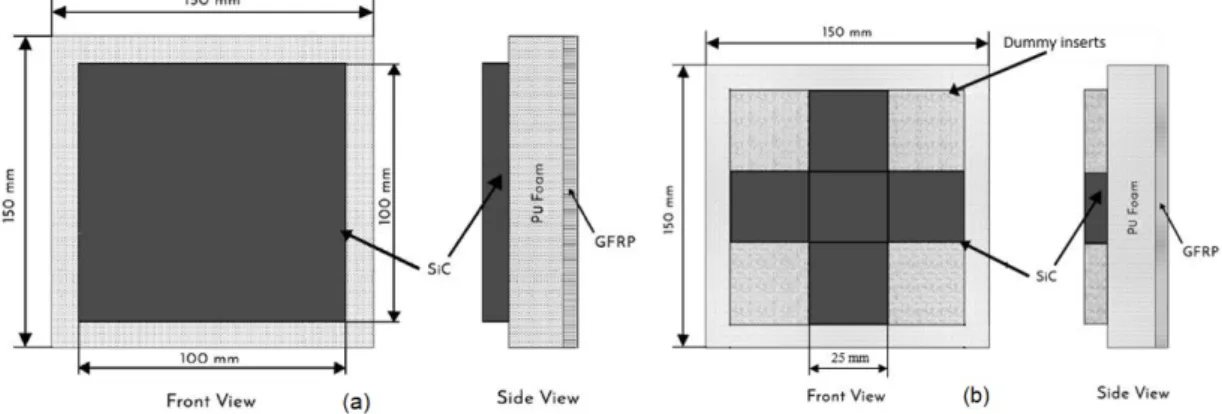
Figure 1: (a) Schematic representation of specimen having front 6mm and 10mm sic plate, (b) Schematic representa-tion of specimen having 6mm sic inserts
Figure 2: Schematic representation of specimen having PUF, PUS and FRP layers
2.2 Impact tests
Figure 3: Drop weight impact testing machine
3 RESULTS
3. Material modelling and numerical simulation
Numerical simulation is carried using AUTODYN which is suitable program to simulate events such as im-pact, penetration, explosions and blast (Century Dynamics, 2013). The laminate is modeled as 100mm by100mm andthe edges are clamped rigidly. Many advanced material models are present in AUTODYN which can very close-ly characterize how the material will behave under impact loading.
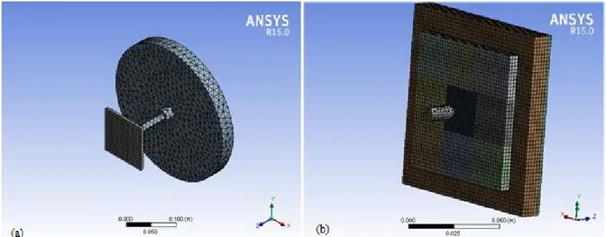
Figure 4: (a) Numerical model of laminates for low velocity impact test, (b) numerical model of laminates for high ve-locity impact test
3.1 Damage mechanism of ceramic
When the impactor impacts upon the ceramic plate the compressive shock waves are generated which prop-agate throughout the plate (Kauffmann et al., 2003). Once it reaches to the rear face it reflects and becomes a ten-sile wave which breaks the ceramic if the magnitude of the tenten-sile wave is more than the tenten-sile strength of ce-ramic (Krishnan et al., 2010). Also, there will be formation of micro cracks which will turn into macro cracks as the time progresses. During this period, more micro cracks will form and finally the ceramic will be broken in granules and powder (Wang et al., 2013). In case of a ductile or flexible backing, the effect of ceramic layer will be enhanced because part of compressive waves will be transmitted to the ductile or flexible backing.
3.1.1 The Johnson-Holmquist models for ceramic
The Johnson–Holmquist (JH) models are constitutive models suitable for predicting the behavior of brittle materials like ceramics subjected to extreme loading. There are two common models namely JH-1 (Johnson and Holmquist, 1990) and JH-2 (Johnson and Holmquist, 1994) used for numerical analysis of ceramics. In the present study, JH-1 model present in AUTODYN is used. In JH-1 model, the material stress is described in the form of line-ar segmented curve of equivalent stress versus pressure (Holmquist and Johnson, 2002). It is illustrated in Fig. 5. At a given pressure, if strain rate increases, then equivalent stress also increases, this makes the material strong-er. But when there is material damage under a given pressure, it will reduce the equivalent stress and hence make the material weaker. The ratio of the total accumulated increment of plastic strain and the equivalent failure strain is termed as damage factor. The material will undergo failure, if negative pressure reaches the tensile limit T or damage factor D is equal to 1.0. Once the material is failed, it cannot withstand any tensile loading but can take some limited amount of compressive loading (Quan et al., 2006). The material data for ceramic is directly taken from the AUTODYN library.
3.2 The hyper-elastic model for Polyurethane polymer
There are various hyper-elastic models like Ogden model, the Van der Waals model, polynomial model etc. available to model the highly non-linear behavior of PU foam. In this paper, Ogden model (Ogden, 1972) is used and the material parameters are taken from the past work (Ferreño et al., 2010). They have also used closed cell PU foam of high density.
1
21 2 3 2
1 1
2
i i i3
1
1
N N i
e i
i i i i
U
J
D
(1)N,
i,
i andD
i are material parameters and N must be chosen a priori by the user.Polyurethane sheet is modelled using linear equation of state, elastic strength model and principal stress failure criteria. The properties are directly taken from the AUTODYN library.
3.3 Composite Modeling
To understand ballistic impact of composite laminates, different failure mechanisms are to be analyzed. The energy absorbing mechanisms are moving cone formation on the back face of the target, elastic deformation and tensile failure of fibers, delamination and matrix crack (Morye et al., 2000). The orthotropic equation of state along with elastic strength model and material stress damage model is used to model the glass epoxy laminate. Delamination is assumed to result from excessive through-thickness tensile stresses or strains and/or from ex-cessive shear stresses or strains in the matrix material. In the incremental constitutive relation below the stress Δσ11 normal to the laminate and the corresponding orthotropic stiffness coefficients Cijare instantaneously set to zero, whenever the failure is initiated in either of those two modes, j=1 in equation (2):
0
0
1, 3
jj
and C
ijC
jifori
(2)11 12 13 12 22 22
11 11
22 13 23 23 22
33 33 44 23 23 31 31 55 12 12 66
0
0
0
0
0
0
0
0
0
0
0 0
0
0
0
0
0 0
0
0
0
0 0
0
c c c
c c c
c c c
c
c
c
(3)Delamination will also occur with a reduction in shear stiffness αand a nominal value of 20% is used for α in the numerical simulations done in this paper. For impactor, the material, Steel 4340 is used which follows shock equation of state and Johnson Cook strength model.
3.5 Material properties
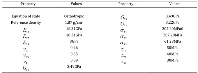
Table 1: Material properties of the glass/epoxy laminate
Property Values Property Values
Equation of state Orthotropic
23
G
3.49GPaReference density 1.87 g/cm3
31
G
3.22GPa 11E
18.31GPa 11
207.20MPa0 22E
18.31GPa 22
207.20MPa 33E
3GPa 33
61.23MPa 12
0.26 12
50MPa 23
0.35 23
40MPa 31
0.09 31
30MPa 12G
3.49GPa4. RESULTS AND DISCUSSION
4.1 Energy absorption in low velocity impact
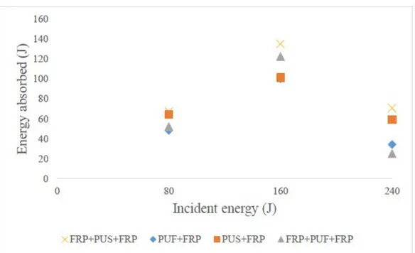
The target specimens of various combinations of GFRP/ PUF/PUS are subjected to low velocity impact at in-cident energies of 80J, 160J and 240J. The experimental results are shown in Fig. 6. When the impactor of mass 16kg is dropped from a height of 0.5m, GFRP laminate absorb 17.73J of energy. Under the same impact conditions, the impactor penetrated through PUF+GFRP specimen which absorbed 48.58J of energy but failed to penetrate through PUS+GFRP laminate which absorbed 64.34J of energy. The later specimen initially absorbs complete 80J of energy and due to the elastic property of PUS, the specimen releases elastic energy to the impactor allowing it to rebound. While, in case of GFRP+PUS+GFRP, the impactor perforates and got struck in the specimen due to friction between impactor and top facing GFRP. In this case, the target material absorbs 67.49J of energy. In all other cases, the impactor is found to penetrate the target material. It is observed that specimen having PUS ab-sorb more energy than the specimen having similar configuration but PUS replaced with PUF. PUS+GFRP abab-sorbs 32%, 1.2% and 18% of energy more than PUF+GFRP at 80J, 160J and 240J of impactor incident energy respec-tively. Similarly, GFRP+PUS+GFRP absorbs 29%, 10% and 182% more than the energy absorbed by GFRP+PUF+GFRP at 80J, 160J and 240Jof impactor incident energy respectively.
Fig. 6: Energy absorbing trend of various target materials at different energy levels
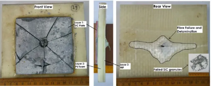
Figure 7 shows front, side and rear views of the PUS+GFRP specimen when it is subjected to 240J of incident impactor energy. Major delamination is observed in the surrounding region of the impacted area in the back end of the GFRP laminate. The delamination area in PUS+GFRP is 2400mm2 which is greater than the delamination area in case of PUF+GFRP (1801 mm2), because of stiffness variation in the core material. PU Sheet is more elas-tically deformable than PUF. This excessive deformation of PUS caused more delamination in composite backing when compared to specimen having PUF.
Figure 7: PUS+GFRP laminate impacted at 240 J of incident energy
laminate at 80J of impactor energy. This specimen absorbs maximum energy in delamination having 8103 mm2 of delamination area as compared to other tested specimens at 80J, 160J and 240J. In this case, the impactor got stuck in the specimen and the energy transfer to the back end GFRP layer is by bending of PU sheet.
Figure 8: Energy absorbed by GFRP+PUS+GFRP laminate impacted at 80j of incident energy
But on reversing the laminate configuration. When the impact is done on the front GFRP layer, interesting observations are made. Figure 9 shows the front, side and rear view of this laminate. The front GFRP layer is pen-etrated, but the back-end PU sheet undergoes excessive bending and it is not penetrated.
Figure 9: GFRP+PUS laminate impacted at 80J of impactor energy
ob-served in the impacted area as well as in its surrounding area. The tensile failure of fibers in surrounding area is due to high stiffness and damage of SiC plate.
A sharp edge is formed on the ceramic due to the formation of radial cracks and compressive failure. This leads to the formation of scratches on the surface of the impactor due to chipping which is seen in Figure 11. When the impact velocity is less than the plastic wave velocity of the impactor, the deformation of the front end of the projectile take place. However, this deformation will stop if the relative velocity at the interface of the target material and the impactor reduces to zero (Naik et al., 2012).
Figure 10: Impact on 6mm thick front facing sic plate layered PUF/GFRP laminate at incident energy of 160J
Figure 11: Scratches and Chipping on the impactor due to sic layer
5. NUMERICAL RESULTS
5.1 Low Velocity Impact
With the above finite element model presented, all experiments described in Section 2 are simulated to ob-tain energy absorbed by the laminate, contact force histories, total deformation, stress variation, deflection and damage area.
Figures 12 (a) to (d) show the results for the damage in the laminate made of PUS+GFRP sheet at various time steps ranging from start of the impact event till the end. It is observed that the impactor penetrates the spec-imen. The gradual increase in deflection of the laminate in Z direction and finally complete perforation failure as seen during the experiments can also be observed in figure 12. In numerical results, it is possible to obtain the deflection of moving cone from AUTODYN result files directly at different time steps during penetration. Also, maximum deflection is found out experimentally by analysing the high-speed movie clips.
Figure 12: Sequence of failure in PU sheet + composite laminate impacted at 80 J
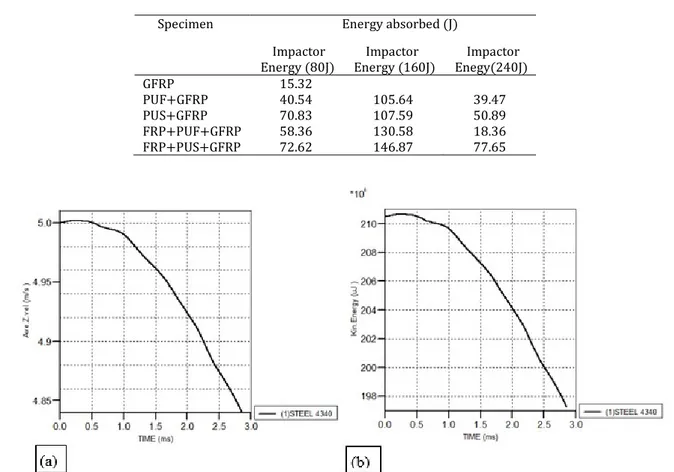
Table 2. Numerical results for the energy absorbed by the sandwiched laminates for various energy of impactor
Specimen Energy absorbed (J)
Impactor
Energy (80J) Energy (160J) Impactor Enegy(240J) Impactor
GFRP 15.32
PUF+GFRP 40.54 105.64 39.47
PUS+GFRP 70.83 107.59 50.89
FRP+PUF+GFRP 58.36 130.58 18.36
FRP+PUS+GFRP 72.62 146.87 77.65
Figure 13: (a) velocity, (b) kinetic energy variation of projectile during perforation for FRP+PUF+FRP for impact at 1.5m
5.2 High Velocity Impact
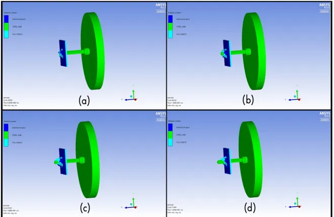
Upon establishing the low velocity impact experiments numerical model, the same model is extended and numerical simulation is carried out to understand the protective behaviour and energy absorbing capacity of the SiC bonded specimens in high velocity impact. As discussed earlier erosion of projectile is observed in case of impact onto SiC plates/inserts. Figure 14 shows the erosion of projectile for the SiC(10mm) + PUF + GFRP spec-imen impacted at 722 m/s. The residual velocity of projectile is 435 m/s and the specspec-imen has absorbed 1328 J of energy. Table 3 shows the energy absorbed and residual velocity of SiC bonded specimens calculated numerically.
Table 3: energy absorbed by the sic layered target materials at high velocity impact in numerical simulation
Specimen Initial
velocity(m/s) velocity(m/s) Residual absorbed (J) Energy
SiC(10mm)+PUF(10mm)+GFRP 722 435 1328
SiC(6mm)+PUS(5mm)+GFRP 721 552 860
SiC(6mm Inserts)+PUF(10mm)+GFRP 732 581 793
Figure 14: SiC (10mm) +PUF+ GFRP specimen subjected to impact at 722 m/s
6. COMPARISON OF NUMERICAL AND EXPERIMENTAL RESULTS
6.1 Energy absorption in various laminates at different energy level
Numerical simulation and experiments are carried out for different incident energy levels. The energy ab-sorbed by the laminates for impact loading at 0.5m height (80 J) is shown for both experimental and numerical values in Figure 16. A good agreement is found between the two. Both experimental and numerical studies re-vealed that energy absorbed by specimen GFRP+PUS+GFRP is better when compared with the other sandwiched specimens. Both studies show that PUS+GFRP and GFRP+PUS+GFRP have absorbed same level of energy. The additional composite layer has not contributed significantly towards the structural performance.
Figure 16: Comparison of energy absorbed numerically and experimentally at when the incident energy was 80 J
The maximum deflection in z-direction for PUS+GFRP specimen is obtained by both numerically as well as experimentally at different impactor energy and are compared in Table 4. It is seen that maximum deflection val-ue before failure increases as the energy level increases, but it is observed up to 160 J impactor energy, at 240J, the specimen is penetrated and the deflection is significantly reduced. Once it is penetrated completely, it cannot provide any resistance to impact and hence deflection reduces.
Table 4: Comparison of deflection value for PUS+FRP specimen
Impactor Energy, J Deflection (Numerical, J) Deflection (Experiment, J)
80 19.896 15.8775
160 36.89 40.54
240 24.563 19.442
Figure 17: (a) Numerical result image for laminate subjected to impact at 160 J (b) cut section view of numerical simu-lation of the laminate
Figure 18: (a) Test image for laminate subjected to impact at 160 J (b) cut section view of the laminate observed after test (c) zoom in view of cut section
Figure 19: Comparison of energy absorbed numerically and experimentally at 240 J
7. CONCLUSIONS
An experimental study is carried out for multilayer target material having various combinations of PUF, PUS and SiC plate/inserts with back end material as GFRP to understand their energy absorbing capacity during im-pact loading. Numerical simulation is carried out to validate the experimental results. The following conclusions are made based on the study:
• At 80 J of impactor energy, the specimen GFRP+PUF is penetrated whereas GFRP+PUS is not penetrated and the impactor is rebounded with 16 J of energy which shows the better performance of PUS as compared to PUF towards impact.
• Extent of delamination in the backend GFRP is very high when it is bonded with PUS than PUF.
• Introduction of SiC plates/inserts as front layer increases the impact resistance as well structural performance.
• The 10mm thickness SiC plate layered target absorbs 12% more energy than 6mm thickness SiC plate layered target material.
• The ballistic performance of SiC(6mm plate)+PUS+GFRP and SiC(6mm Inserts)+PUF+FRP are same at high velocity impact, but damage is local in case of SiC inserts layered target and it can also undergo multiple impacts at different locations.
• Good agreement is seen between the results of numerical modelling and experimental.
References
Abdel-Nasser Yehia, Elhewy Ahmed M.H. and Al-Mallah, Islam (2016). Impact analysis of composite laminate us-ing finite element method, Ships and Offshore Structures,12(2): 219-226. DOI: 10.1080/17445302.2015.1131005
Akshaj K. V., Surya P., Pandit, M.K. (2017). Low Velocity Impact Response of Composite/Sandwich Structures, Key Engineering Materials, 725, 127-131.
Balaganesan G and Chandra Khan V, (2016). Energy absorption of repaired composite laminates subjected to im-pact loading, Composites Part B, 98: 39-48. doi: 10.1016/ j.compositesb.2016.04.083.
Balaganesan G, Velmurugan R, Srinivasan M, Gupta N. K., and Kanny K. (2014). Energy absorption and ballistic limit of nanocomposite laminates subjected to impact loading, International Journal of Impact Engineering, 74:57-66.
Bhatnagar A, (2006). Lightweight ballistic composites: military and law-enforcement applications, CRC Press.
Century Dynamics. 2013. ANSYS Autodyn User's Manual, Release 15.0.
Feli S. and Asgari M.R. (2011). Finite element simulation of ceramic/composite armor under ballistic impact, Composites: Part B, 42:771–780
Ferreño Diego, Carrascal Isidro A., Cicero Sergio and Meng, E. (2010). Characterization of Mechanical Properties of a Shock Absorber Polyurethane Foam for Elevators. Numerical Fitting of Mechanical Behavior Models for Hy-perelastic and Elastomeric Foam Materials, Journal of Testing and Evaluation, 38 (2): 211-221.
Ghalami-Choobar Mehran and Sadighi, Mojtaba (2014). Investigation of high velocity impact of cylindrical projec-tile on sandwich panels with fiber–metal laminates skins and polyurethane core, Aerospace Science and Technol-ogy, 32:142–152
Ghosh A. and Sinha P.K. (2005). Initiation and propagation of damage in laminated composite shells due to low velocity impact, International Journal of Crashworthiness, 10:4, 379-388, DOI: 10.1533/ijcr.2005.0354
Holmquist TJ and Johnson GR. (2002). Response of silicon carbide to high velocity impact, J ApplPhys, 91(9):5858–66.
Inai R, Chirwa E C, Saito H, Uozumi T, Nakai A and Hamada, H (2003). Experimental investigation on the crushing properties of carbon fibre braided composite tubes, International Journal of Crashworthiness, 8:5, 513-521, DOI: 10.1533/ijcr.2003.0253
Johnson GR and Holmquist TJ. (1994). An improved computational constitutive model for brittle materials, In: High pressure Science and technology, New York: American Institute of Physics, 981-984.
Johnson GR and Holmquist, TJ. (1990). A computational constitutive model for brittle materials subjected to large strains, high strain rates, and high pressure, Proceedings of EXPLOMET conference, San Diego.
Karandikar P. G. (2009). A review of ceramics for armor applications. The American Ceramic Society, Advances in Ceramic Armor IV, 29:163–175.
Kauffmann C, Cronin D, Worswick M, Pageau G and Beth A. (2003). Influence of material properties on the ballis-tic performance of ceramics for personal body armor. Shock Vib, 10:51–58
Krishnan K, Sockalingam S, Bansal S and Rajan SD. (2010). Numerical simulation of ceramic composite armor subjected to ballistic impact, Compos Part B Eng., 41:583-93.
Long Shuchang, Yao Xiaohu and Zhang Xiaoqing (2015). Delamination prediction in composite laminates under low velocity impact, Composite Structures, 132:290–298.
Morye S.S, Hine P.J, Duckett R. A., Carr D.J, Ward I.M, (2000). Modeling of the energy absorption by polymer composites upon ballistic impact, Composites Science and Technology, 60:2631-2642.
Naik, N. K., Kumar, S., Ratnaveer, D., Joshi, M., and Akella, K. (2012). “An Energy-Based Model for Ballistic Impact Analysis of Ceramic-Composite Armors,” Int. J. Damage Mech., 22(2):1–43.
Ogden, R. W. (1972). Large deformation isotropic elasticity – on the correlation of theory and experiment for in-compressible rubberlike solids, Proc. R. Soc. Lond., A, 326:565–584.
Quan, X, Clegg RA, Cowler MS, Birnbaum NK and Hayhurst CJ. (2006). Numerical simulation of long rods impact-ing silicon carbide targets usimpact-ing JH-1 model, International Journal of Impact Engineerimpact-ing, 33:634–644
Sekine H., Hu N., Fukunaga H. and Natsume T. (1998). Low velocity impact response of composite laminates with a delamination, Mechanics of Composite Materials and Structures, 5:3, 257-278.
Shim V.P.W., Tu Z.H. and Lim C.T. (2000), Two-dimensional response of crushable polyurethane foam to low ve-locity impact, International Journal of Impact Engineering, 24:703-731.
Velmurugan R, Ganesh Babu M and Gupta N K (2006). Projectile impact on sandwich panels, International Journal of Crashworthiness, 11:2, 153-164, DOI: 10.1533/ijcr.2005.0385. Online link: http://dx.doi.org/10.1533/ijcr.2005.0385
Velmurugan R. and Balaganesan G. (2013). Energy absorption characteristics of glass/epoxy nano composite lam-inates by impact loading, International Journal of Crashworthiness, 18:1, 82-92.
Wang Jie, Waas Anthony M. and Wang Hai (2013). Experimental and numerical study on the low-velocity impact behavior of foam-core sandwich panels, Composite Structures, 96:298–311.
Wilkins ML, (1978). Mechanics of penetration and perforation, Int J EngSci, 16:793-807.
Yazdani Nezhad, H., Merwick, F., Frizzell R.M. and McCarthy C.T. (2015). Numerical analysis of low-velocity rigid-body impact response of composite panels, International Journal of Crashworthiness, 20:1, 27-43, DOI: 10.1080/13588265.2014.963378