Abstract
The present study is based on experimental investigation and nu-merical simulation of impact of different nose shape projectiles on thin polycarbonate plates. Rigid hardened projectiles of two different geometries (Blunt and Truncated cone) keeping the same shank di-ameter and total mass were prepared. These projectiles were im-pacted through pneumatic gun setup on circular polycarbonate plates at varying impact velocities upto 106 m/s. Impact and residual ve-locities were measured before and after perforation, respectively. Nu-merical simulations were performed in ABAQUS/EXPLICIT finite element code. The problem has been modelled based on Mie-Grunei-sen equation of state.
The experimental results obtained in terms of ballistic limit, residual velocity, energy absorbed and deformation mechanism have been compared with the numerical results and are found to be in excellent agreement. It is observed that the ballistic limit for normal impact is greater for blunt projectile compared to truncated conical projec-tile. Velocity drop and the energy absorbed is higher for blunt pro-jectile compared to truncated conical propro-jectiles for the impact ve-locities under study.
Keywords
Experimental; Ballistic; Polycarbonate; ABAQUS/Explicit; Sub-ordnance velocity.
Experimental and Numerical Investigation of Perforation of Thin
Polycarbonate Plate by Projectiles of Different Nose Shape
1 INTRODUCTION
Polycarbonate (PC) is a transparent material which offers high specific strength, good resistance to static and impact loads and as such found extensive application in optical lenses, automotive parts, house hold application, safety devices etc. and desired to act as protective structures against impact loading. The mechanism of penetration by a projectile and the associated damage characteristics should be analysed for the efficient design of PC structures. The maximum velocity of the projectile at which the complete perforation takes place with zero exit velocity referred to as ballistic limit
Afsar Husain Raisuddin Ansari Arshad Hussain Khan *
Department of Mechanical Engineering, Aligarh Muslim University, Aligarh 202001, U.P., India.
[email protected], [email protected], [email protected]
* Corresponding author, [email protected]; [email protected]
http://dx.doi.org/10.1590/1679-78253252
together with the modes of energy absorption in the deformation process can be utilised for the efficient design of the protective PC structures.
A number of investigations have been carried out to characterize the static/dynamic flow and failure properties of polycarbonate structures viz: Ravi-Chandar (1995); Rittel et al. (1997); Rittel and Levin (1998); Rittel (1999, 2000); Moisa et al. (2005); and Sarva et al. (2007). The penetration behavior of PC structures has been analysed by Wright et al. (1992), based on quasi-static deep penetration tests using circular cylindrical hardened steel punches. The resistance of thin PC plates (2, 5 and 12 mm thick) to impact by round and cylindrical projectiles was investigated experimentally by Wright et al. (1993). It is concluded that the five different modes of deformation are present i.e. elastic dishing, petalling, deep penetration, cone cracking and plugging. Inclined impact on thin PC plates (less than 6.4 mm thick) has also been investigated by Li and Goldsmith (1997), and it is concluded that the resulting perforated hole exhibits a much smaller diameter than the projectile, indicating a substantial capability for recovery. The ballistic resistance of clamped thin PC plates to single (Qasim and Yousif, 2008) and multiple ballistic impacts (Qasim, 2009) is analysed and it is concluded that reinforcements should be provided near the clamped edges.
The projectile geometry and the nose shape is an important factor affecting the mechanism of deformation of the target plates and relatively fewer studies are carried out to investigate their influ-ence on metallic plates. Wingrove (1973) studied the influinflu-ence of projectile geometry on aluminum alloy targets and concluded that blunt projectiles can penetrate more efficiently followed by hemi-spherical and ogive nosed projectiles, respectively, if the target thickness to projectile diameter ratio is less than one. Ipson et al. (1977) found that blunt projectiles penetrated the target more efficiently than conical projectiles when the thickness of target was moderate. For the case of thin and thick targets however, an opposite trend was observed.
It is evident from the literature survey that the influences of projectile geometry (nose shapes), impact velocities and target thickness on the impact behavior of PC plates has not been adequately analysed. The present work deals with experimental as well as numerical investigation of impact behavior of PC plates which can serve as benchmark for the efficient design of PC structures subjected to impact loading. The experimental analysis has been carried out using a Pneumatic gun setup with provisions of measurement of impact and residual velocities under normal/oblique impact. The pro-jectiles of different geometries/nose shapes but of same material are manufactured and heat treated by keeping their mass and diameter constant achieved by varying the shank length.
A number of experiments are conducted to investigate the influences of nose shape and impact velocity and the performance parameters in terms of ballisitic limit, velocity drop, energy absorbed and deformation modes are investigated. Finite element simulation of the problem was carried out using finite element code ABAQUS. Residual velocities as well as the ballistic limit of the projectiles were obtained using the post processing module of the code. The predicted values of residual velocities were compared with the experiments and good correlation was found between the two. The predicted failure mechanism of the target plates is also found in good agreement with that observed experimentally.
2 EXPERIMENTAL ANALYSIS
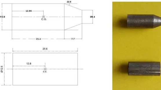
and they are heat treated by raising the temperature to 920 °C. Subsequently oil quenching is done at room temperature for obtaining the desired hardening of the projectiles. The hardened projectiles is then tested on Rockwell hardness testing machine and it is found that the hardness of the projectiles correspond to 64-65 Rh (Rockwell hardness number). The hardness is brought to the desired range of 47- 50 Rh by tempering. The dimensions and final shape of the projectiles are shown in Fig. 1. The projectiles were so designed that their mass remains same which is achieved by varying the shank length of the projectiles and keeping their diameter same.
Figure 1: Schematics and camera view of Truncated cone and Blunt projectile.
The mechanical properties of the target (PC) plate is evaluated from the tensile test on UTM. A standard tensile specimen as per ASTM standards is cut from PC plate to evaluate the properties of PC. Stress strain diagram of PC is shown in Fig. 2 and the evaluated properties are tabulated in Table 1. Circular target plate of PC whose mechanical properties have been evaluated is shown in Fig. 3. The thickness of the plate is 2.66 mm and the outer diameter is 255 mm. In order to rigidly secure the target PC plate for impact testing on the pneumatic gun setup eight holes are drilled at pitch circle of 230 mm diameter. The effective diameter of target plate is 205mm.
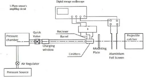
The schematics and the pictorial view of the Pneumatic gun-setup is shown in Fig. 4 which is employed for impact testing. Pneumatic gun setup consist of a pressure source, regulator, pressure chamber, projectile chamber, barrel, optical fibre sensor for measuring the impact velocity, dual screen of aluminium foil for measuring the residual velocity of projectile. The impact velocity in the experi-ment is varied between 65 m/s to 106 m/s. Impact energy is calculated by calculating the kinetic energy of the projectile (Ei =0.5*m*v²) where m is the mass of projectile and v is the impact velocity
same equation. The energy absorbed is calculated by taking the difference of impact energy and residual energy.
Figure 2: Stress-strain diagram of polycarbonate.
Youngs modulus E (N/mm2) 2000
0.2% offset Yield Stress (N/mm2) 55
Elongation at Peak (%) 10.9
Elongation at Break (%) (Total Elongation) 114.7
Table 1: Results of stress v/s strain graph.
Figure 4: Schematic diagram of the Pneumatic gun setup.
3 NUMERICAL ANALYSIS
The finite element analysis is carried out based on axi-symmetric model on ABAQUS CAE. Axi-symmetric analytically rigid projectiles were modelled as per the geometry employed in the experi-ments. The projectile is given a reference point at center of gravity of the whole body. The plate is modeled as axi-symmetric deformable body with shell feature and two partitions were constructed on it. The first partition was supposed to be an impact zone, at center, where the projectile has actually made contact with the plate, the second partition was made to observe the local deformation, around the impact zone. The projectile and plate is being assembled together along the axis of symmetry line as shown in Fig. 5. The projectile was initially kept a little away from the plate, to notice its first indentation.
Figure 5: Plate partition and its enlarged view.
The Mie- Grüneisen equation of state is linear in energy and can be represented by
Γ (1)
where and are the Hugoniot pressure and specific energy (per unit mass) and are functions of density ( ) only, and Γ is the Grüneisen ratio defined as
Γ Γ (2)
where Γ is a material constant and is the reference density. The Hugoniot energy, is related to the Hugoniot pressure by
(3)
where is the nominal volumetric compressive strain. Elimination of Γ and from the above equations yields
Γ
Γ (4)
The equation of state and the energy equation represent coupled equations for pressure and in-ternal energy. These equations are solved simultaneously at each material point by Abaqus/Explicit solver.
The Hugoniot pressure , is a function of density only. A common fit to the Hugoniot data is given by:
(5)
where and s define the linear relationship between the linear shock velocity, and the particle
velocity, , as follows:
(6)
With the above assumptions the linear Hugoniot form is written as
² Γ (7)
where is equivalent to elastic bulk modulus at small nominal strains. There is a limiting com-pression given by the denominator of this form of the equation of state
or (8)
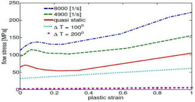
Dorogoy, 2008), which uses a linear extrapolation for plastic strains up to 1. The strain stress curve for strain rates is assumed to be identical to that of 8000 1/s. It was assumed that at T=100°C for all strain rates, the PC softens and the yield stress is half of the quasi-static one, while at T=200°C it drops almost to zero, and the material flows freely (Bauwens et al., 1972). The damage initiation values are specified in Table 3. These values are based on experimental results obtained by torsional split Hopkinson bar (Fleck et al., 1990) in which fracture occurred at shear strain 1.5 <<2.0. The linear displacement damage evolution value used is 80 mm, which was also used for PMMA in Dorogoy et al. (2010).
Density ρ [Kg/m³] 1200
Specific Heat [J/Kg.K°] 1300
Inelastic heat fraction 1
Reference density ρₒ [Kg/m³] 1910
Bulk sound speed cₒ [m/s] 1933
Slope s in Us versus Up diagram 2.65
Gruneisen coefficient Γₒ 0.61
Table 2: Physical property and Hydrodynamic data for the polycarbonate (Dorogy et al., 2011).
Strain rate [1/s] Polycarbonate
Quasi static 1.0
4900 0.85
8000 0.85
80000 0.60
Damage evolution [µm] 80
Table 3: Damage initiation values and damage evolution for polycarbonate (Fleck et al., 1990).
Figure 6: Plastic properties of polycarbonate used in modelling polycarbonate (Rittel and Dorogoy, 2008).
formu-lation. The penetration of slave nodes into the master surface is eliminated at the end of each incre-ment. The projectile was considered as the master surface and the impact region of the plate is modelled as node based slave surface. The frictional effect between the plate and projectile is assumed negligible because of small thickness of the plate. The number of elements chosen for the discretization of polycarbonate plate is based on mesh convergence.
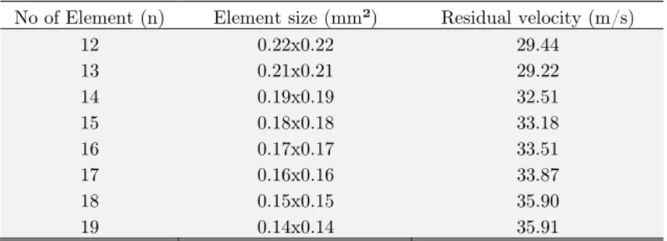
A mesh sensitivity analysis has been carried out to confirm that the results obtained are not sensitive to mesh size. Blunt projectile impacting the polycarbonate plate with an impact velocity of 88.24 m/s is considered. Eight different mesh sizes by varying the number of element from 12 to 19 (element length from 0.22 to 0.15 mm, respectively) are considered and the results for residual velocity corresponding to each mesh size is presented in Table 4 and the convergence is plotted in Fig. 7. Aspect ratio is the number of elements taken along the length to the number of elements along the thickness direction. When this ratio approaches unity, Zukas et al. (2000) suggested that simulation approaches its real values. The numbers of elements were varied along the thickness direction from 12 to 19 and aspect ratio of the elements was kept close to unity. The condition for a unity aspect ratio is recommended (as some dependency upon the mesh does remain) but is not essential, as we are using the damage initialization and damage evolution criteria for defining damage. The predicted numerical value of the residual velocity for different number of elements is also compared with the experimental residual velocity and the results have been plotted in Fig. 7. It can be seen that the solution converges for 18 number of elements with element length equal to 0.15 mm. Hence the number of element choosen for the numerical analysis is 18.
No of Element (n) Element size (mm²) Residual velocity (m/s)
12 0.22x0.22 29.44
13 0.21x0.21 29.22
14 0.19x0.19 32.51
15 0.18x0.18 33.18
16 0.17x0.17 33.51
17 0.16x0.16 33.87
18 0.15x0.15 35.90
19 0.14x0.14 35.91
Table 4: Mesh convergence and element size.
The ballistic limit is estimated based on the U.S. military standard (MIL-STD-662E, 1987). This standard defines theballistic limit by taking the average of equal number of highest partial penetra-tion velocities and lowest complete penetrapenetra-tion velocities which occur within a specific range. The ballistic limit has been estimated from present FE model from velocity time histories, for an initial impact velocity at the stage when the residual velocity reaches close to zero. The ballistic limit velocity obtained from FE analysis and experimental predictions are found to be in excellent agreement. The above validation implies that the present FE model is capable of simulating the ballistic impact response of Polycarbonate target.
4 RESULTS AND DISCUSSION
(a) Normal Impact of Blunt Projectile
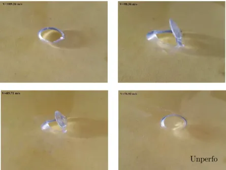
The ballistic performance of the PC plate has been evaluated by calculating the percentage of energy absorbed by the target and residual velocities. A number of experiments on polycarbonate plates of thick-ness 2.66 mm were carried out to study the response of the plates subjected to normal impact of blunt projectile. Impact velocity of the projectile is varied from 76 m/s to 106 m/s and the numerical simulation is also carried out in the same velocity range. The geometry of the target, projectile and the boundary conditions remain same. The mode of deformation of the PC plate after impact through the pneumatic gun setup at different velocities is shown in Fig. 8. It is observed from the experimental investigations that the plug remains attached to the plate below 100m/s. The experimental results obtained in terms of residual velocity, absorbed energy and residual energy are tabulated in Table 5 whereas the numerical results obtained from simulation in ABAQUS are presented in Table 6. The comparison of the experi-mental results with the numerical results reveal close agreement between the two. The comparison of the back face signature of the perforated plate shown in Fig. 9, reveal similar kind of burr in the plate end and the shape of the plug is similar in experimental as well as simulated results.
S.No Specimen No Impact Ve-locity (m/s) Residual Velocity (m/s) Velocity Drop (m/s) Impact En-ergy (J) Residual Energy (J) Absorbed Energy (J)
1 BP1 106.19 64.25 41.94 143.77 52.63 91.14
2 BP7 105.26 62.15 43.11 141.27 49.25 92.02
3 BP8 101.69 55.23 46.46 131.85 38.89 92.95
4 BP2 98.36 49.79 48.57 123.35 31.61 91.74
5 BP4 88.24 34.12 54.12 99.28 14.84 84.43
6 BP6 85.71 0 85.71 93.66 0 93.66
7 BP5 76.92 N.P.
N.P. – Plate is not perforated
Table 5: Experimental results of Blunt projectile on polycarbonate plate.
S.No Impact Ve-locity (m/s) Residual Velocity (m/s) Velocity Drop (m/s) Impact Energy (J) Residual Energy (J) Absorbed Energy (J)
1 106.19 67.02 39.17 143.77 57.27 86.50
2 105.26 65.52 39.74 141.27 54.73 86.53
3 101.69 59.99 41.70 131.85 45.88 85.96
4 98.36 53.16 45.20 123.35 36.03 87.32
5 88.24 35.90 52.34 99.28 16.43 82.84
6 85.71 2.5 83.21 93.66 0.08 93.58
7 76.92 N.P.
N.P. – Plate is not perforated
Table 6: Numerical result of Blunt projectile on polycarbonate plate.
(b) Normal Impact of Truncated Cone Projectile
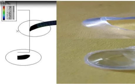
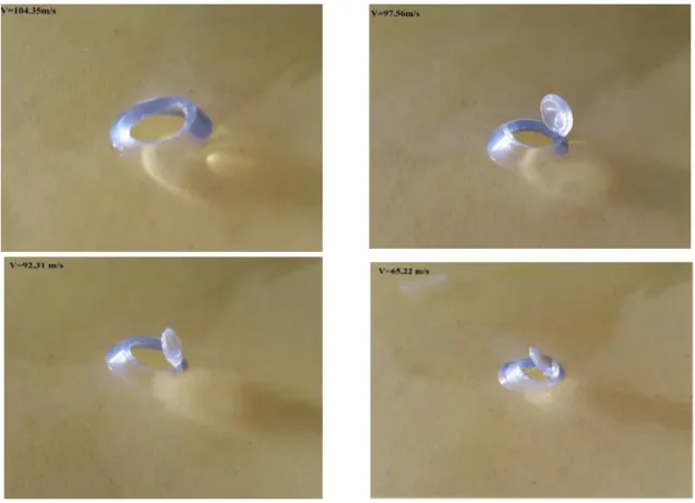
In order to analyse the influence of nose shape on the impact response of polycarbonate plates of thickness 2.66 mm a number of experiments were carried out using truncated cone projectile. The shape of the projectile is changed without altering its diameter and mass by varying the shank length. Impact velocity is varied from 65 m/s to 105 m/s and numerical simulation is also carried out in the same velocity range. The deformed configuration of the PC plate obtained experimentally after impact at different velocities is shown in Fig.10. It can be seen that the plug remains attached to the plate below the impact velocity of 100 m/s. A detailed parametric analysis is carried out and the experi-mental results pertaining to residual velocity, velocity drop and residual/absorbed energies corre-sponding to different impact velocities of the truncated cone projectiles are tabulated in Table 7. The numerical results obtained by simulation using ABACUS-CAE are presented in Table 8. The com-parison of the experimental and simulation results shown in Table 7 & 8, reveal excellent agreement between the two. The deformed configuration and the back face signature of the perforated plate obtained from experiments and numerical simulation are compared in Fig. 11,which shows a similar kind of deformation pattern and the shape of the plug is similar in both the analysis i.e. the plug is thin at the ends from both side.
Figure 11: Comparison of back face signature of perforated plate from experimental/simulation for truncated cone projectile.
S.No Specimen
No. Impact Ve-locity (m/s) Residual Ve-locity (m/s) Velocity Drop (m/s) Impact Energy (J) Residual Energy (J) Absorbed Energy (J)
1 TP2 104.35 62.2 42.15 138.83 49.33 89.51
2 TP3 97.56 57.19 40.37 121.35 41.70 79.65
3 TP5 92.31 48.95 43.36 108.64 30.55 78.09
4 TP4 91.6 48.55 43.05 106.98 30.05 76.93
5 TP6 85.11 47.19 37.92 92.36 28.39 63.96
6 TP7 76.43 31.44 44.99 74.48 12.60 61.88
7 TP8 65.22 0 0 54.23 0 54.23
Table 7: Experimental result of Truncated Cone projectile on polycarbonate plate.
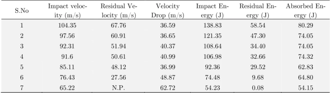
S.No Impact
veloc-ity (m/s) Residual Ve-locity (m/s) Velocity Drop (m/s) Impact En-ergy (J) Residual En-ergy (J) Absorbed En-ergy (J)
1 104.35 67.76 36.59 138.83 58.54 80.29
2 97.56 60.91 36.65 121.35 47.30 74.05
3 92.31 51.94 40.37 108.64 34.40 74.05
4 91.6 50.61 40.99 106.98 32.66 74.32
5 85.11 48.12 36.99 92.36 29.52 62.83
6 76.43 27.56 48.87 74.48 9.68 64.80
7 65.22 N.P. 62.72 54.23 0.08 54.15
N.P. – Plate is not perforated
(c) Effect of Nose Shape on the Response Parameters
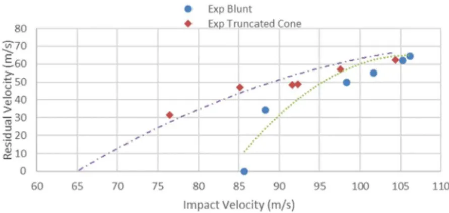
The influence of the nose shape on the residual velocity for different impact velocities is shown in Fig. 12. It can be inferred from the figure that the residual velocity is nearly same for blunt as well as truncated cone projectiles at higher impact velocities however at impact velocities up to 100 m/s, the residual velocity for truncated cone projectile is significantly greater than that for blunt projectile. It has been observed that the truncated cone projectile has perforated the PC plate at much lower impact velocity compared to blunt projectile.
Figure 12: Variation of the residual velocity for different nose shape projectile.
Figure 13 shows the variation of the velocity drop with increasing impact velocities by different projectiles. At lower impact velocities, it is observed that the velocity drop is more for blunt projectiles compared to truncated cone projectile.
Figure 13: Variation of the velocity drop for different nose shape projectile.
absorbed is more at lower impact energy compared to truncated cone projectile. The effect of nose shape is more prominent at low impact energy. This is because of greater contacting area as well as larger shearing area for blunt projectile compared to conical projectile. Further the global deformation (dishing) is large (refer Fig. 16) at lower impact velocity resulting in larger energy absorption for blunt projectiles compared to conical projectiles.
Figure 14: Variation of the energy absobed for different nose shape projectile.
Figure 15: Plate profile for impact velocity greater than 100 m/s.
The local/global deformation pattern (plate profile) obtained experimentally during the normal impact of blunt and truncated cone projectiles at different impact velocities are shown in Fig.’s 15-16. It can be seen from Fig. 15 that for impact velocity greater than 100 m/s the global deformation or dishing and local deformation or bulging are same for both blunt as well as truncated cone projec-tile. However, for impact velocity below 100 m/s greater bulging is observed in truncated cone pro-jectile which may be attributed to half conical shape of the propro-jectile (Fig. 16). Around the periphery of the deformed plate dishing (global deformation) is same for both blunt and truncated cone projec-tiles however as we move towards the center from the periphery both dishing as well as bulging (local deformation) is greater for truncated cone projectiles as compared to blunt projectile.
4 CONCLUSIONS
The response of polycarbonate plate subjected to normal impact by Blunt and Truncated cone pro-jectiles in the sub ordnance velocity range has been analyzed experimentally as well as by axi-sym-metric numerical simulations using ABAQUS-CAE. The present analysis can be used as a benchmark for designing protective equipment’s/components subjected to impact loading. Based on the detailed investigations the following conclusions can be drawn:
i.The ballistic limit of 2.66 mm thick polycarbonate plate for normal impact of blunt and trun-cated-cone projectile is found to be 81.32 m/s and 70.83 m/s, respectively. The values obtained experimentally are found to be in close proximity with the simulation results.
ii.The plug remains attached from the plate in both type of projectiles (blunt and truncated cone) at impact velocities below 100 m/s.
iii.At higher impact velocities greater than 100 m/s the velocity drop for both the projectiles is found to be almost same. This may be due to the fact that plug starts detaching after this velocity and shearing force is applied to all the circumference of petal to detach it from the plate com-pletely.
iv.The velocity drop increases rapidly at higher impact velocity and the rate of increase is more in blunt projectile as compared to truncated cone projectile.
v.Energy absorbed is more in blunt projectile as compared to truncated cone projectile.
vi.For impact velocity less than 100 m/s greater bulging is observed in truncated cone projectile which may be attributed to half conical shape of the projectile.
Acknowledgement
The authors acknowledge the financial support from DST-PURSE, Government of India.
References
Abaqus/CAE version 6.9-EF1. (2009), Abaqus documentation. Abaqus Analysis User's manual, chapters 20- 22, Das-sault systemes. New York: Springer.
Bauwens-Crowet, C., Bauwens, J.C., Homes, G. (1972), The temperature dependence of yield of polycarbonate in uniaxial compression and tensile tests. J Mater Sci.; 7: 176-183.
Dorogy, A., Rittel, D., Brill, A. (2011), Experimentation and modeling of inclined ballistic impact in thick polycar-bonate plates. Int J Impact Engg.; 38: 804-814.
Fleck, N.A., Stronge, W.J., Liu, J.H. (1990), High strain-rate shear response of polycarbonate and polymethyl meth-acrylate. Proc R Soc Lond A; 429:459e79.
Ipson, T.W., Recht, R.F. (1977), Ballistic Perforation by Fragments of Arbitrary Shape, NWC TP 5927. Denver Research Institute,Naval Weapons Centre, China Lake, CA, USA.
Li, K., Goldsmith, W. (1997), Perforation of steel and polycarbonate plates by tumbling projectiles. Int J Solids Struct; 34: 35-36: 4581-4596.
Military Standard V50 Ballistic Test for Armor (1987), MIL-STD-662E.
Moisa, S., Landsberg, G., Rittel, D., Halary, J.L. (2005), Hysteretic thermal behavior of amorphous semi-aromatic polyamides. Polym J ; 46: 25: 11870-11875.
Qasim, H.S., Yousif, A.A. (2008), Effect of distance from the support on the penetration mechanism of clamped circular polycarbonate armor plates. Int J Impact Eng; 35: 11: 1244-1250.
Qasim, H.S. (2009), Impact resistance of a rectangular polycarbonate armor plate subjected to single and multiple impacts. Int J Impact Eng; 36:9: 1128-1135.
Ravi-Chandar, K. (1995), On the failure mode transitions in polycarbonate under dynamic mixed mode loading. Int J Solids Struct; 32: 6-7: 925-938.
Rittel, D., Dorogoy, A. (2008), A methodology to assess the rate and pressure sensitivity of polymers over a wide range of strain rates. J Mech Phys Solids.; 56: 3191–3205
Rittel, D., Levin, R., Maigre, H. (1997), On dynamic crack initiation in polycarbonate under mixed mode loading. Mech Res Commun; 24: 1: 57-64.
Rittel, D., Levin, R. (1998), Mode-mixity and dynamic failure mode transitions in polycarbonate. Mech Mater: 30: 3: 197-216.
Rittel, D. (1999), On the conversion of plastic work to heat during high strain rate deformation of glassy polymers. Mech Mater; 31: 2: 131-139.
Rittel, D. (2000), Experimental investigation of transient thermoplastic effects in dynamic fracture. Int J Solids Struct; 37: 21: 1 : 2901-2913.
Sarva, S., Mulliken, A.D., Boyce, M.C. (2007), Mechanics of Taylor impact testing of polycarbonate. Int J Solids Struct; 44: 7-8: 2381-2400.
Wingrove, A.L. (1973), The influence of projectile geometry on adiabatic shear and target failure. Metallurgical Trans-actions A 4, 1829–1833.
Wright, S.C, Fleck, N.A., Stronge, W.J. (1993), Ballistic impact of polycarbonate—An experimental investigation. Int J Impact Eng; 13: 1: 1-20.
Wright, S.C., Huang, Y., Fleck, N.A. (1992), Deep penetration of polycarbonate by a cylindrical punch. Mech Mater; 13: 4: 277-284.