Abs tract
In the present study, dynamic pull-in instability of electrostatica
l-ly-actuated micro-beams is investigated through proposing the nonlinear frequency amplitude relationship. An approximate an a-lytical expression of the fundamental natural frequencyis presen t-ed by modern asymptotic approach namely Iteration Perturbation Method (IPM). Influences of vibrational amplitude as well as different parameters on dynamic pull-in voltage are investigated. It is demonstrated that two terms in series expansions is sufficient to produce an acceptable solution of the mentioned micro -structure. The simulations from numerical methods verify the
validity of the analytical procedure.
Key words
Iteration Perturbation Method, Frequency – amplitude relatio n-ship, Dynamic pull-in voltage, Micro-beam Vibration, Pull-in instability.
Application of Iteration Perturbation Method in
studying dynamic pull-in instability of micro-beams
1 IN T R O D U C T IO N
The application of the micro-scale devices is continuously growing and the microelectromechanical systems (MEMS) have become the interesting area of research in recent years. The application of actuated MEMS includes accelerometers, micro-pumps, micro-resonators and manipulators (Grandinetti et al., 2012). In recent years, several researches have been developed on the nonline-ar behavior of MEMS/NEMS devices (Sedighi, 2014; Rahaeifnonline-ard et al., 2013; Tadi Beni et al., 2012; Abdi et al., 2011; Sedighi et al., 2014; Tadi Beni and Abadyan, 2013; Soroush et al., 2010; Sedighi and Shirazi, 2013; Ansari et al., 2012). In the dynamic analysis of micro-systems, electro-static forces cause the relationship between the input excitation and the output response to be nonlinear which is performed by applying voltage between the micro-beam and the substrate. The micro-beam deflection increases by increasing the actuation voltage. At a specific voltage namely pull-in voltage instability happens and the micro-structure drops to the substrate.
Rahaeifard et al. (2013) investigated the dynamic behavior of micro-cantilevers under suddenly applied DC voltage based on the modified couple stress theory using numerical and analytical approaches. Stability of a functionally graded (FG) micro-beam, based on modified couple stress theory (MCST), subjected to nonlinear electrostatic pressure and thermal changes have been
H am id M . Se di g hia , *, Farh an g Dan e sh ma ndb, c , d an d A m in Y a-g hoo ti ana
a
Department of Mechanical Engineering, Shahid Chamran University, Ahvaz, Iran
b
Department of Mechanical Engineering, McGill University, 817 Sherbrooke Street West, Montreal, Quebec, Canada H3A 2K6
c
Department of Bioresource Engineering, McGill University, 21111 Lakeshore Road, Sainte-Anne-de-Bellevue, Quebec, Canada H9X 3V9
d
School of Mechanical Engineering, Shiraz Universi-ty, Shiraz, Iran
*
Latin American Journal of Solids and Structures 11 (2014) 1078-1090
the displacement representation of the first-order shear deformation shell theory for orthotropic materials for modeling the microtubule.
Recently, new asymptotic methods have been increasingly developed in order to solve nonline-ar differential equations (Shi-Jun Liao, 2004; Sedighi and Shirazi, 2012; Sedighi et al., 2012a, 2012b). There have been several approaches employed to solve the governing nonlinear differen-tial equations to study the nonlinear vibrations such as Energy Balance Method (Ghadimi et al., 2012), Variational Iteration Method (He, 2007; Sedighi et al., 2012), and Hamiltonian Approach (HA) (He, 2010; Sedighi and Shirazi, 2013), Amplitude–frequency formulation (He, 2008), Max-Min approach (He, 2008), Homotopy Analysis Method (HAM) (Liao, 2003 and 2004), Parameter Expansion Method (Wang and He, 2008; He, 2002), Homotopy Perturbation Method (HPM) (Yazdi, 2013), Iteration Perturbation Method (He, 2001; Sedighi et al., 2013). The Iteration Per-turbation Method (IPM), which is developed by Ji-Huan He (2001), provides an effective and efficient tool for solving an extensive range of nonlinear equations.
The present article attempts to indicate the impact of vibrational amplitude on dynamic pull-in pull-instability of actuated micro-beams by pull-introducpull-ing the nonlpull-inear frequency – amplitude rela-tionship. In this direction, analytical expressions for vibrational responses of cantilever and clamped-clamped micro actuated beams are presented. The results presented in this paper exhibit that the analytical method is very effective and convenient for nonlinear vibration for which the highly nonlinear governing equations exist. The proposed analytical method demonstrates that two terms in series expansions is sufficient to obtain a highly accurate solution of micro-beam vibration. Finally, the influences of amplitude and significant parameters on the pull-in instability behavior are studied.
2 EQ U A T IO N O F M O T IO N
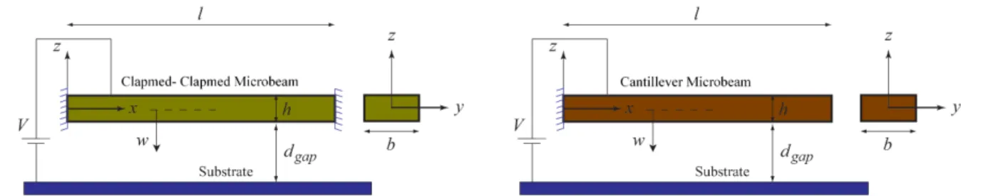
Consider an actuated micro-beam suspended above a rigid substrate and under electro-statically actuated voltage as shown in Fig. 1. The cantilever and clamped-clamped micro beams have length l, thickness h, width b, density ρ, moment of inertia I and a modulus of elasticity E.
The air initial gap is dgap and an attractive electrostatic force which originates from voltage V
causes the micro-beam to deform.
Figure 1Configuration of a: clamped-clamped and b: cantilever micro actuated beam
micro-Latin American Journal of Solids and Structures 11 (2014) 1078-1089 beam are taken into account. The governing equation of motion of micro actuated beam is ex-pressed as follows (Moghimi Zand and Ahmadian, 2009):
ρbhw
tt+EIwxxxx− Ni+
Ebh
2l wx 2dx 0 l
∫
⎛ ⎝ ⎜⎜ ⎜⎜⎜ ⎞ ⎠ ⎟⎟⎟ ⎟⎟⎟w xx−bεV2
2 1
d
gap 2 +
2w x
( )
,t dgap
3 +
3w x
( )
,t 2 dgap
4 +
4w x
( )
,t 3 dgap
5 +
5w x
( )
,t 4 d gap 6 ⎛ ⎝ ⎜⎜ ⎜⎜ ⎜⎜⎜ ⎞ ⎠ ⎟⎟⎟ ⎟⎟⎟ ⎟⎟−εβV2
2 1
dgap + w x
( )
,td
gap 2 +
w x
( )
,t 2 dgap 3 +
w x
( )
,t 3 dgap 4 +
w x
( )
,t 4 d gap 5 ⎛ ⎝ ⎜⎜ ⎜⎜ ⎜⎜⎜ ⎞ ⎠ ⎟⎟⎟ ⎟⎟⎟ ⎟⎟=0(1)
Where N
irepresents the axial force. By introducing the following non-dimensional variables
τ= EI
ρbhl4t, W=
w dgap,ξ=
x
l, α=6 dgap h ⎛ ⎝ ⎜⎜ ⎜⎜⎜ ⎞ ⎠ ⎟⎟ ⎟⎟ ⎟⎟ 2
,λ2
=24εl
4
V2
Eh3
dgap3 ,fi=
Nil2
EI ,γ= dgap
b (2)
the non-dimensional nonlinear governing equation of motion can be written as follows:
∂2
W
∂τ2 + ∂4
W
∂ξ4 − fi+α
∂W ∂ξ ⎛ ⎝ ⎜⎜ ⎜⎜ ⎞ ⎠ ⎟⎟⎟ ⎟ 2 dξ 0 1
∫
⎛ ⎝ ⎜⎜ ⎜⎜ ⎜⎜ ⎞ ⎠ ⎟⎟⎟ ⎟⎟⎟⎟∂ 2 W∂ξ2
−λ 2
4
1+2W+3W2+4W3+5W4
(
)
−βλ2 γ 4
1+W+W2+W3+W4
(
)
=0(3)
Assuming W
( )
ξ,τ =q( )
τ φ ξ( )
, where φ ξ( )
is the first eigenmode of the micro-beam vibrationand can be expressed as:
φC−C
( )
ξ =cosh( )
λ1ξ −cos( )
λ1ξ −cosh λ
1
( )
−cos λ1
( )
sinh λ1
( )
−sin λ1
( )
(
sinh( )
λ1ξ −sin( )
λ1ξ)
clamped-clamped
micro beam (4-a)
φC−F
( )
ξ =cosh( )
λ2ξ −cos( )
λ2ξ − cosh λ2
( )
+cos λ 2( )
sinh λ2
( )
+sin λ 2( )
(
sinh( )
λ2ξ −sin( )
λ2ξ)
cantilever micro
beam (4-b)
whereλ
Latin American Journal of Solids and Structures 11 (2014) 1078-1090 d2
q
( )
τdτ2 +β1q
( )
τ + β2(
q( )
τ)
2+β3
(
q( )
τ)
3+β4
(
q( )
τ)
4+β0
⎡ ⎣ ⎢ ⎢
⎤ ⎦ ⎥
⎥=0 (5)
where the parameters β0to β
4 for clamped-clamped as well as cantilever micro-beam have been described in the Appendix A.
3 A P P R O X IM A T IO N B Y T H E IT E R A T IO N P E R T U R B A T IO N M E T H O D
The Iteration Perturbation Method proposed by He (2001) is constructed based on perturbation technique coupling with iteration method. This method is valid not only for weakly nonlinear problems but also for strongly nonlinear differential equations. Consider the nonlinear equation (5), in order to obtain an iteration perturbation solution of the governing equation, an artificial parameter ε should be introduced as:
d2q
dτ2 +εq β1+β2q+β3q 2
+β4q 3
(
)
+εβ0 =0 (6)Equation (6) can be approximated by:
d2q
dτ2 +εq β1+β2q0+β3q0
2
+β4q0 3
(
)
+εβ0 =0 (7)where q0 is the initial approximate solution. The initial solution can be assumed in the form
q0=Acos
( )
ωτ , where ω is the unknown angular frequency and should be determined. Substitutingq0 into equation (6) yields
d2
q
dτ2+
εq β1+Aβ2cos
(
ωτ)
+A2β3
(
cos(
ωτ)
)
2+A3β4
(
cos(
ωτ)
)
3(
)
+εβ0 =0 (8)Equation (8) can be rewritten in the following form
d2q dτ2+
εβ1q+ εAβ2q+ 3
4εA 3
β4q ⎛
⎝ ⎜⎜ ⎜
⎞
⎠ ⎟⎟
⎟⎟cos
(
ωτ)
+ 12εqβ3A 2 ⎛
⎝ ⎜⎜ ⎜
⎞
⎠ ⎟⎟
⎟⎟cos 2
(
ωτ)
+ 38εqβ3A 4
+1 2εqβ3A
2
+εβ0+ 1
4εqβ4A 3cos 3
ωτ
(
)
=0(9)
assuming that
q=q0+εq1+ε 2
q2+... (10)
εβ1=ω2+εc
Latin American Journal of Solids and Structures 11 (2014) 1078-1089 Substituting equations (10) and (11) into (9), and equating the coefficients of the same power of e, the following differential equation for q
1 can be obtained
d2 q1
dτ2 +ω 2
q1 =− 3
4β3A 3
+Ac1
⎛ ⎝ ⎜⎜ ⎜ ⎞ ⎠ ⎟⎟
⎟⎟cos
(
ωτ)
−1
2β4A 4
+1
2β2A 2 ⎛ ⎝ ⎜⎜ ⎜ ⎞ ⎠ ⎟⎟
⎟⎟cos 2
(
ωτ)
− 1
4β3A 3 ⎛ ⎝ ⎜⎜ ⎜ ⎞ ⎠ ⎟⎟
⎟⎟cos 3
(
ωτ)
−1
8β4A 4
cos 4
(
ωτ)
−12β2A 2
−3
8β4A 4
−β0
(12)
If the term cos
(
ωτ)
exists in the right hand side of equation (12), the secular term τcos(
ωτ)
will appear in the final solution. Therefore, the coefficient of this term in (12) should be equal to zero, so we havec
1 =−
3
4β3
A2 (13)
similarly, the following differential equation for q
2 can be obtained
d2q2
dτ2 +ω 2
q2+
cos
(
ωτ)
3840ω2
960β
2 2
A3−756
β4 2
A7−330
β3 2
A5−2880
β4β0A 3−192
β4β4A 5
(
+960β3β2A4
+576β3β4A6
+2880β3β0A2
)
+cos 2
(
ωτ)
3840ω2 −1120β3β2A 4
+640β22
A3
(
1920β
4β0A 3
+1024β
4β2A 5−887
β3β4A 6
+384β
4 2
A7−1920β
3β0A 2
+1920β
2β0A
)
+
cos 3
(
ωτ)
3840ω2
960β3β0A2−960
β4β0A3−108
β42
A7
+192β3β4A6
+96β4β2A5
+320β22
A3
(
−60β
3 2
A5+320
β3β2A
4
)
+cos 4(
ωτ)
3840ω2
480β
4β0A 3+182
β4β3A 6+96
β4 2
A7+220
β3β2A 4+160
β4β2A 5
(
)
+cos 5
(
ωτ)
3840ω292β
4 2
A7+30β
3 2
A5+96β
4β2A 5
(
)
+23β3β4A6cos 6
ωτ
(
)
3840ω2 +
β42
A7cos 7
ωτ
(
)
960ω2
580β3β2A4
+490β4β3A6
+960β3β0A2
+864β4β2A5
+288β42
A7
+1440β4β0A3
+1920β2β0A+640β22
A3
3840ω2 =0
(14)
No secular term in the second equation for q2
( )
τ yields:c c 2,ω
(
)
=−1440β4β0A3+1920Ac 2ω2−800β 2
2A3−378β 4
2A7−1920β
2β0A−1120β2β4A 5+15β
3
2A5 =0 (15)
thereby, solving equations (11) and (15) with ε=1 for fundamental frequency gives the following
frequency amplitude relationship for actuated micro-beam vibrations as:
ω
( )
A = β12 + 3
8β3A
2
+ β1 2
4 + 3β1β3A
2
8 +
19β3 2
A4
128 − 3β4β0A
2
4 −
7β2β4A 4
12 −
5β2 2
A2
12 − 63β4
2
A6
Latin American Journal of Solids and Structures 11 (2014) 1078-1090
Solving Eq. (12) for q1
( )
τ gives the following second order approximation for q( )
τ as:q
( )
τ =Acos(
ωτ)
−cos
(
ωτ)
−48β4A4−80β2A2
+30β3A3 −240β
0
(
)
240ω2
+
cos
(
ωτ)
180β3A3(
)
+cos 2(
ωτ)
320β4A4+320β2A2
(
)
+cos 3(
ωτ)
60β3A3(
)
1920ω2
+16β4A 4
cos 4
(
ωτ)
−1920β0−960β2A2−720β4A4 1920ω2
(17)
4 R ESU LT S A N D D ISC U SSIO N
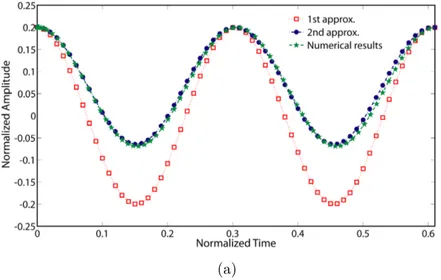
To indicate the validity of proposed solution by IPM, the analytical solutions at the side of corre-sponding numerical results have been plotted. As can be seen in Fig. 2, the second order approxi-mation of q
( )
τ using analytical methods for both clamped-clamped and cantilever micro-beamshow good agreement with numerical results from fourth-order Runge-Kutta method. The numeri-cal values of system parameters used for asymptotic analysis are described in Appendix B.
(a)
Figure 2Comparison of the results of analytical solutions with the numerical solution forA=0.2. Symbols: numerical solution; Solid line: analytical solutions
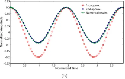
Latin American Journal of Solids and Structures 11 (2014) 1078-1089 (b)
Figure 2 (continued) Comparison of the results of analytical solutions with the numerical solution forA=0.2. Symbols: numerical solution; Solid line: analytical solutions
a: Clamped-clamped and b: Cantilever micro-beam
Analytical simulation of the dimensionless dynamic pull-in voltage of clamped-clamped and can-tilever micro-beam versus non-dimensional amplitude are depicted in Figs. 3 to 5. The effect of di-mensionless axial force parameter fi on the dynamic pull-in voltage as a function of initial ampli-tude is illustrated in Fig. 3. It is obvious that the dynamic pull-in voltage increases by increasing the axial force parameter. It appears from Fig. 3 that the dynamic pull-in voltage decreases when the normalized amplitude increases. Fig. 3 also shows that the effect of normalized amplitude on the dynamic pull-in voltage is more considerable than its effect on the axial force parameterfi. Fig. 4 shows the characteristic curves of dynamic pull-in voltage of double clamped micro-beam for vari-ous values of dimensionless parameter α. Fig. 4 indicates that the dynamic pull-in voltage increases
as the parameter αincreases. In addition, the impact of dimensionless parameter ais more
consid-erable when the normalized amplitude increases from zero to unity.
Latin American Journal of Solids and Structures 11 (2014) 1078-1090
Figure 4 Dimensionless dynamic pull-in voltage of clamped-clamped micro-beam versus parameterα
Figure 5 Dimensionless dynamic pull-in voltage of clamped-clamped micro-beam versus parameterγ
The influence of nondimensional parameter γ on the dynamic pull-in voltage of cantilever and double clamped actuated micro-beams are depicted in Figs. 5 and 6. The comparison between the values of pull-in voltages reveals that the dynamic pull-in voltage for cantilever micro-beam is less than its value for double clamped one. From Figs. 5 and 6, it is concluded that the increase in the parameter γ causes decrease in the dynamic pull-in voltage. Furthermore, it is clear that the effect
Latin American Journal of Solids and Structures 11 (2014) 1078-1089 Figure6 Dimensionless dynamic pull-in voltage of cantilever micro-beam versus parameter γ
5 C O N C LU SIO N S
A modern powerful analytical approach called Iteration perturbation method was employed to es-tablish the frequency - amplitude relationship of vibrating actuated micro-beams. The influence of vibrational amplitude on pull-in instability and dynamic pull-in voltage was investigated in this research. The accuracy of the obtained analytical solutions is verified by numerical results. It is indicated that two terms in series expansions is sufficient to produce an acceptable accurate solu-tions. Finally, the significant effects of non-dimensional parameters on the dynamic pull-in voltage were investigated.
References
Abdi, J., Koochi, A., Kazemi, A.S., Abadyan, M., (2011). Modeling the effects of size dependence and disper-sion forces on the pull-in instability of electrostatic cantilever NEMS using modified couple stress theory, Smart Mater. Struct., 20, 055011, doi:10.1088/0964-1726/20/5/055011.
Ansari, R.R., Gholami, R.R., Sahmani, SS., (2012). Study of Small Scale Effects on the Nonlinear Vibration Response of Functionally Graded Timoshenko Microbeams Based on the Strain Gradient Theory, J. Comput. Nonlinear Dynam., 7(3), 031009, doi:10.1115/1.4006040.
Chouvion, B., Mc William, S., Popov, A.A., Fox, C.H.J., (2012). Review and comparison of different support loss models for micro-electro-mechanical systems resonators undergoing in-plane vibration, Proceedings of the Institution of Mechanical Engineers, Part C: Journal of Mechanical Engineering Science, 226(1), 283-295.
Daneshmand, F., Amabili, M., (2012). Coupled oscillations of a protein microtubule immersed in cytoplasm: an orthotropic elastic shell modeling, J Biol Phys, 38, 429–448, DOI 10.1007/s10867-012-9263-y.
Ghadimi, M., Barari, A., Kaliji, H.D., Domairry, G., (2012). Periodic solutions for highly nonlinear oscillation systems, Archives of Civil and Mechanical Engineering, 12(3), 389–395.
Latin American Journal of Solids and Structures 11 (2014) 1078-1090
He, J.H., (2001). Iteration Perturbation Method for Strongly Nonlinear Oscillations, Journal of Vibration and Control, 7, 631-642, DOI: 10.1177/107754630100700501.
He, J.H., (2002). Modified Lindstedt–Poincare methods for some strongly non-linear oscillations: Part I: ex-pansion of a constant, International Journal of Non-Linear Mechanics, 37(2), 309-314.
He, J.H., (2007). Variational iteration method—Some recent results and new interpretations, Journal of Com-putational and Applied Mathematics, 207(1), 3-17.
He, J.H., (2008). Max-Min approach to nonlinear oscillators. International Journal of Nonlinear Sciences and Numerical Simulation, 9, 207-210.
He, J.H., (2008). An Improved Amplitude-frequency Formulation for Nonlinear Oscillators, International Journal of Nonlinear Sciences and Numerical Simulation, 9(2), 211-212.
He, J.H., (2010). Hamiltonian approach to nonlinear oscillators, Physics Letters A, 374(23), 2312-2314.
Kumar, V., Rhoads, J.F., (2012). Modeling and Analysis of an Optically-Actuated, Bistable MEMS Device, J. Comput. Nonlinear Dynam., 7(2), 021007, doi:10.1115/1.4005080.
Liao, S.J., (2003). An analytic approximate technique for free oscillations of positively damped systems with algebraically decaying amplitude, International Journal of Non-Linear Mechanics, 38(8), 1173-1183.
Liao, S.J., (2004). An analytic approximate approach for free oscillations of self-excited systems, International Journal of Non-Linear Mechanics, 39(2), 271-280.
Motallebi, A., Fathalilou, M., Rezazadeh, G., (2012). Effect of the open crack on the pull-in instability of an electrostatically actuated micro-beam, Acta Mechanica Solida Sinica, 25(6), 627-637.
Moghimi Zand, M. Ahmadian, M.T., (2009). Application of homotopy analysis method in studying dynamic pull-in instability of Microsystems. Mechanics Research Communications, 36, 851–858.
Ramezani, S., (2012). A micro scale geometrically non-linear Timoshenko beam model based on strain gradient elasticity theory, International Journal of Non-Linear Mechanics, 47(8), 863-873.
Rahaeifard, M., Ahmadian, M.T., Firoozbakhsh, K., (2013). Size-dependent dynamic behavior of microcantile-vers under suddenly applied DC voltage, Proc IMechE Part C: J Mechanical Engineering Science, in press, DOI: 10.1177/0954406213490376.
Rajabi, F., Ramezani, S., (2013). A nonlinear microbeam model based on strain gradient elasticity theory, Ac-ta Mechanica Solida Sinica, 26(1), 21-34.
Rhoads, J.F., Kumar, V., Shaw, S.W., Turner, K.L., (2013). The non-linear dynamics of electromagnetically actuated microbeam resonators with purely parametric excitations, International Journal of Non-Linear Me-chanics, 55, 79-89.
Sabater, A.B., Rhoads, J.F., (2012). On the Dynamics of Two Mutually-Coupled, Electromagnetically-Actuated Microbeam Oscillators., J. Comput. Nonlinear Dynam., 7(3), 031011, doi:10.1115/1.4005999.
Sedighi, H.M., Shirazi, K.H., (2012). A new approach to analytical solution of cantilever beam vibration with nonlinear boundary condition. Journal of Computational and Nonlinear Dynamics, 7(3), doi:10.1115/1.4005924.
Sedighi, H.M., Shirazi, K.H., Zare, J., (2012). Novel Equivalent Function for Deadzone Nonlinearity: Applied to Analytical Solution of Beam Vibration Using He’s Parameter Expanding Method. Latin American Journal of Solids and Structures, 9, 443–451.
Latin American Journal of Solids and Structures 11 (2014) 1078-1089 Sedighi, H.M., Shirazi, K.H., (2013). Vibrations of micro-beams actuated by an electric field via Parameter Expansion Method, Acta Astronautica, 85, 19-24.
Sedighi, H.M., Shirazi, K.H., Attarzadeh, M.A., (2013). A study on the quintic nonlinear beam vibrations us-ing asymptotic approximate approaches, Acta Astronautica, 91, 245-250, doi:10.1016/j.actaastro.2013.06.018. Sedighi, H.M., (2014). Size-dependent dynamic pull-in instability of vibrating electrically actuated microbeams based on the strain gradient elasticity theory, Acta Astronautica, 95, 111-123. http://dx.doi.org/10.1016/j.actaastro.2013.10.020.
Sedighi, H.M., Changizian, M., Noghrehabadi, A., (2014). Dynamic pull-in instability of geometrically nonline-ar actuated micro-beams based on the modified couple stress theory, Latin American Journal of Solids and Structures, 11, 810-825.
Soroush, R., Koochi, A., Kazemi, A.S., Noghrehabadi, A., Haddadpour, H., Abadyan, M., (2010). Investigating the effect of Casimir and van der Waals attractions on the electrostatic pull-in instability of nano-actuators, Phys. Scr., 82, 045801, doi:10.1088/0031-8949/82/04/045801.
Tadi Beni, Y., Abadyan, M., (2013). Use of strain gradient theory for modeling the size-dependent pull-in of rotational nano-mirror in the presence of molecular force, Int. J. Mod. Phys. B 27, DOI: 10.1142/S0217979213500835.
Tadi Beni, Y., Koochi, A., Kazemi, A.S., Abadyan, M., (2012). Modeling the influence of surface effect and molecular force on pull-in voltage of rotational nano–micro mirror using 2-DOF model, Canadian Journal of Physics, 90(10), 963-974, 10.1139/p2012-092.
Vahdat, A.S., Rezazadeh, G., Ahmadi, G., (2012). Thermoelastic damping in a micro-beam resonator tunable with piezoelectric layers, Acta Mechanica Solida Sinica, 25(1), 73-81.
Wang, S.Q., He, J.H., (2008). Nonlinear oscillator with discontinuity by parameter-expansion method, Chaos, Solitons & Fractals, 35(4), 688-691.
Yazdi, A.A, (2013). Homotopy Perturbation Method for Nonlinear Vibration Analysis of Functionally Graded Plate, Journal of Vibration and Acoustics, doi: 10.1115/1.4023252.
Zamanzadeh, M., Rezazadeh, G., Jafarsadeghi-poornaki, I., Shabani, R., (2013). Static and dynamic stability modeling of a capacitive FGM micro-beam in presence of temperature changes, Applied Mathematical Model-ling, 37(10–11), 6964-6978.
Appendix A
For clamped-clapmed micro beam the defined parameters are:
β1=λ1
4−
fi φC−CφC−′′Cdξ 0
1
∫
−λ2
4
2+γβ
(
)
β2=−λ
2
4
3+γβ
(
)
φC−3 Cdξ
0 1
∫
β3=−
λ2 4
4+γβ
(
)
φC−C4
dξ
0 1
∫
−α φC−CφC′′−C φC′−C 2dξ
0 1
∫
⎡⎣ ⎢ ⎢ ⎢
⎤
⎦ ⎥ ⎥ ⎥dξ 0
1
∫
⎛⎝ ⎜⎜ ⎜⎜ ⎜
⎞
⎠ ⎟⎟⎟ ⎟⎟⎟
β4=−
λ2
4
5+γβ
(
)
φC−C5
dξ
0 1
Latin American Journal of Solids and Structures 11 (2014) 1078-1090
β0 =−
λ2
4
1+γβ
(
)
φC−Cdξ0 1
∫
For cantilever micro beam the defined parameters are:
β1=λ24−λ2
4
(
2+γβ)
β2=−
λ2
4
3+γβ
(
)
φC−F3
dξ
0 1
∫
β3=−
λ2 4
4+γβ
(
)
φC−F4 dξ
0 1
∫
β4=−λ 2
4
5+γβ
(
)
φC−F5 dξ
0 1
∫
β0=−
λ2
4
1+γβ
(
)
φC−Fdξ0 1
∫
Appendix B
System parameters used for numerical analysis
l=210µm micro-beam length h=1.5µm micro-beam thickness
E =169 GPa modulus of elasticity b=0.5µm micro-beam width
ρ=2329kg/m3 density d
gap=1.18µm initial gap