Abs tract
The present article deals with static and dynamic behavior of functionally graded skew plates based on the three–dimensional theory of elasticity. On the basis of the principle of minimum potential energy and the Rayleigh Ritz method, the equations of motion are derived in conjunction with the graded finite element approach. Solution of the resulted system of equations in time domain is carried out via Newmark’s time integration method. Calculations are applied for fully clamped boundary condition. In the present paper, two different sets of distributions for material properties are considered. For the static analysis, material proper-ties are considered to vary through the thickness direction accord-ing to an exponential law. In the case of dynamic analysis, varia-tions of the volume fracvaria-tions through the thickness are assumed to obey a power law function. Thus, the effective material properties at each point are determined by the Mori–Tanaka scheme. In case of dynamic analysis, the results are obtained for uniform step loadings. The effects of material gradient index and skew angle on displacement components and stress response are studied. Results of present formulations are verified by available results of a func-tionally graded rectangular plate for different boundary conditions and also compared with result of a homogenous skew plate by commercial FEM software.
Key words
Skew plate; graded finite elements; three–dimensional elasticity; functionally graded materials.
Dynamic and Static analysis of FGM Skew plates with
3D Elasticity based Graded Finite element Modeling
1 INTRODUCTION
Functionally graded materials (FGMs) stand as a class of novel composite materials in which me-chanical properties vary in one, two or even three specific direction(s). FGMs are especially compo-site materials constructed from two or more constituent phases with defined composition (Miya-moto et al. 1999; Suresh and Mortensen 1998). Unlike the traditional composites which are piece-wise homogeneous mixtures or layered structures, the main feature of structures made of FGMs is
Kam ran A s e mi*, 1, Sa tta r Je da ri Sa la mi2, Ma nou ch eh r S al eh i3, Mo jtab a Sa di gh i4
1 Ph.D. student, Mechanical Engineering Department, Amirkabir University of Tech-nology, Tehran, Iran
2 Ph.D. student, Mechanical Engineering Department, Amirkabir University of Tech-nology, Tehran, Iran
3 Associate Professor, Mechanical Engineering Department, Amirkabir University of Tech-nology, Tehran, Iran
4
Associate Professor, Mechanical Engineering Department, Amirkabir University of Tech-nology, Tehran, Iran
Received in 01 May 2013 In revised form 16 May 2013
the continuous variation of material properties. Some benefits assigned to FGMs that distinguish them from laminated composites are such as removing the delamination mode of failure, reducing thermal stresses, residual stresses and stress concentration effects. Therefore, the FGMs could be meaningful in practical applications in which the operating conditions are strict, especially in high temperature environments such as in high speed spacecrafts, heat–engine components or rocket heat shields. Skew plates appear in many fields of engineering, such as civil, mechanical, and aerospace engineering. This in turn, it is important to study the static and dynamic behaviors of FGM skew plates to obtain the optimum conditions by choosing the appropriate material distribution profile.
To date, a wide range of research has been carried out on static and dynamic analysis of func-tionally graded structures which mostly have used the beam, plate and shell theories (Damanpack et al. 2013; Kiani and Eslami 2013; Taj 2013). For thin plates, the classical plate theory (CPT) is used to analyze functionally graded (FG) plate structures. The CPT leads to significant errors in analyzing thick plates because of omitting the influence of shear deformation through the thickness of FG plate structures. As a result, in order to improve the CPT for moderately thick and thick FG plates, some modifications are applied to include the effects of transverse shear deformation. There-fore, the first, third and higher order shear deformation theories and also the 3D elasticity solutions are considered. Among these analyses, 3D elasticity analysis of plates not only provides realistic and accurate results by considering all stress and strain components but also allows further physical insights, which cannot otherwise be estimated by the other two-dimensional or plate theory anal-yses. Different closed form and approximate solutions have been proposed so far for static and dy-namic analysis of skew plates by using the ESL (Equivalent Single-layer) plate theories. Das and et al. (2008) studied Large-amplitude free vibration analysis of simply supported thin isotropic skew plates. The large deformation was imparted statically by subjecting the plate to uniform transverse pressure. Young et al. (2002) presented an investigation into the dynamic stability of skew plates simultaneously under an aerodynamic force in the chordwise direction and a random in-plane force in the spanwise direction. Prabhu et al. (1972) studied the stability of clamped skew plates with the in- plane stresses represented in terms of oblique components. Xiang et al. (1995) formulated the free vibration analysis of skew Mindlin plates with intermediate parallel stiffeners attached in two directions. Akishev et al. (2011) generalized the known analytical solutions of the linearized stability problems for rectangular hinged plates under the combined loading to the similar problems for skew plates, the deformation mechanics of which is described by the equations of the classical theory formed in oblique Cartesian coordinates.
Wu et al. (2006) studied dynamic instability and nonlinear response of rectangular and skew lami-nated plates subjected to periodic in-plane load. Park et al. (2008) performed a structural dynamic analysis of skew sandwich plates with laminated composite faces based on high-order shear defor-mation plate theory (HSDT). The effects of skew angles and layup sequences on dynamic response for various parameters were studied using a nonlinear high-order finite element program developed for this study. Lee (2010) studied the finite element dynamic stability analysis of laminated compo-site skew structures subjected to in- plane pulsating forces based on the higher-order shear defor-mation theory (HSDT). Qing- qing (1991) discussed the elastic equilibrium problems of anisotropic skew thin plate of variable thickness simply supported on all four sides by nonlinear theories, and used the Navier method to seek an approach to the problem, and to illustrate the solution with examples. Ray et al. (1994) studied nonlinear static and dynamic behaviors of freely supported Rhombic sandwich plates following Banerjee's hypothesis.
Among the FGM plate structures, little attention has been given to FGM skew plates than those of rectangular one. Ganapathi et al. (2006) investigated thermal buckling of a simply supported FG skew plate using first- order shear deformation theory in conjunction with the finite element ap-proach. The effects of aspect and thickness ratios, gradient index, and skew angle on the critical buckling temperature difference are brought out. Upadhyay et al. (2013) studied static and dynamic behavior of FG skew plates. The equations of motion were derived using a higher order shear de-formation theory in conjunction with von-Karman’s nonlinear kinematics. In case of dynamic analy-sis, the results were achieved for uniform step, sine, half sine, triangular and exponential type of loadings. The effects of volume fraction index, skew angle and boundary conditions on nonlinear displacement and moment response were presented. Sundararajan et al. (2005) discussed the free vibration characteristics of FGM rectangular and skew plates subjected to thermal environment employing the nonlinear formulation developed based on von Karman's assumptions. The variation of nonlinear frequency ratio with amplitude was highlighted considering various parameters such as gradient index, temperature, thickness and aspect ratios, and skew angle.
study between graded finite element and boundary element formulations capable of modeling non-homogeneous behavior of the FGM structures. They showed that using conventional finite element modeling where material properties are constant within an element for dynamic problems leads to considerable discontinuities and inaccuracies. On the other hand by using graded finite element method in which material properties are graded continuously through the elements, the accuracy of the results can be improved without increasing the mesh size.
To the best knowledge of the authors, there are no studies available in the literature on static and dynamic analyses of skew plates based on 3D elasticity and graded finite elements.
In this paper, static and dynamic analysis of functionally graded skew plates based on three di-mensional elasticity and graded finite element method is investigated. For the static analysis, mate-rial properties are considered to vary through the thickness direction according to an exponential law. For the dynamic analysis, variations of the volume fractions through the thickness are assumed to follow a power law function. In this case, the effective material properties at each point are de-termined by the Mori–Tanaka scheme. The governing equations are derived based on principle of minimum potential energy and Rayleigh Ritz method. To solve the time dependent equations, Newmark’s numerical integration method is employed. The effects of material gradient index and skew angle on static and dynamic behavior of FG skew plates have been investigated.
2 THE GOVERNING EQUATIONS
2.1 Material gradient and geometry
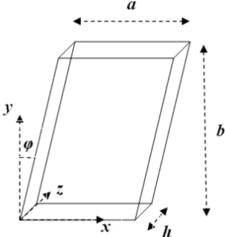
A functionally graded skew plate as shown in Figure 1 is considered in the present analysis. The Cartesian coordinates vary within the
(0 < x ≤ a+b tg (φ)), (0 < y ≤ b) and (0 < z ≤ h)
intervals where a and b/cos(φ) are the sides and h is the thickness of skew plate. The FG skew plate is sub-jected to a uniform pressure on its upper surface, while its lower surface is free of tractions. Gener-ally, two different sets of distributions for material properties are considered. For the static analysis, FGM is considered in which material properties vary through the thickness of the skew plate ac-cording to an exponential lawE
=
E
0exp
z
h
⎛
⎝⎜
⎞
⎠⎟
n⎛
⎝
⎜⎜
⎞
⎠
⎟⎟
(1)where n is the non- negative material gradient index and
E0
is Young’s modulus of the lower sur-face of the skew plate.For the dynamic analyses, it is assumed that the FGM skew plate is made of two randomly dis-tributed isotropic phases and the composition of the FGM varies through the thickness direction of the skew plate. The volume fraction of ceramic and metal phases are given by
V
c=
1−
z
h
⎛
⎝⎜
⎞
⎠⎟
nV
m
=
1
−
V
c (2-b)where n is a non–negative volume fraction index and the subscripts c and m stand for the ceramic and the metal phases, respectively.
Mori–Tanaka homogenization method (Mori and Tanaka 1973) is used to determine the effective properties at each point. According to this method, the effective bulk modulus (K) and the effective shear modulus (G) of the FGM skew plate are defined by
K
−
K
cK
m
−
K
c=
V
m1
+
1
−
V
m
(
)
K
m
−
K
c(
)
K
c+
4
3
G
c(3)
G
−
G
cG
m−
G
c=
V
m1
+
(
1
−
V
m)
(
G
m−
G
c)
G
c+
f
c(4)
where
f
c=
G
c9
K
c
+
8
G
c(
)
6
K
c
+
2
G
c(
)
(5)The effective values of the Young’s modulus and the Poisson’s ratio of the FG skew plate could be written as
E
=
9
KG
3
K
+
G
(6)ν
=
3K
−
2G
2 3K
(
+
G
)
(7)Figure 1 Geometric parameters of the FGM skew plate.
2.2 Equations of Motion
The equations of motion in term of stresses in the rectangular Cartesian coordinates for an FGM skew plate can be written as
∂
σ
xx
∂
x
+
∂
σ
xy
∂
y
+
∂
σ
zx
∂
z
=
ρ
( )
z
∂
2u
∂
t
2(8-a)
∂
σ
xy∂
x
+
∂
σ
yy∂
y
+
∂
σ
yz∂
z
=
ρ
( )
z
∂
2v
∂
t
2(8-b)
∂
σ
zx
∂
x
+
∂
σ
yz
∂
y
+
∂
σ
zz
∂
z
=
ρ
( )
z
∂
2w
∂
t
2(8-c)
where ρ is the mass density which depends on z coordinate. Also u, v and w are the displacement components through the x, y and z directions, respectively and
σ
ij
(
i
,
j
=
x
,
y
,
z
)
are the stresscom-ponents.
2.3 Stress-Strain Relations
The stress–strain relations of the linear elasticity from the Hook’s law in term of the modulus of elasticity and Poisson’s ratio are (Zienkiewicz 2005)
=
σ
D
ε
(9){
σ
xxσ
yyσ
zzσ
xyσ
yzσ
zx}
=
Tσ
(10){
ε
xxε
yyε
zzε
xyε
yzε
zx}
=
Tε
(11)(
)
(
)(
)
1
0
0
0
1
0
0
0
1
0
0
0
0
0
0
0
0
0
0
0
1
1
1
1
1
1
( ) 1
1 2
1
1 2
2(1
)
1 2
2(1
)
1
0
0
0
0
0
0
0
2
2(1
)
( )
E z
E z
ν
ν
ν
ν
ν
ν
ν
ν
ν
ν
ν
ν
ν
ν
ν
ν
ν
ν
ν
ν
ν
⎛
⎞
⎜
⎟
⎜
⎟
⎜
⎟
⎜
⎟
⎜
⎟
⎜
⎟
⎜
⎟
⎜
⎟
⎜
⎟
⎜
⎟
⎜
⎟
⎜
−
−
−
−
−
−
−
=
−
+
−
−
⎟
⎜
⎟
⎜
⎟
⎜
⎟
⎜
⎟
−
⎝
=
Ω
−
⎠
−
−
D
(12)where D is the elastic coefficients matrix. It is assumed that the elasticity modulus E varies in the z direction while Poisson’s ratio ν is considered to be constant. The invariant part of matrix D is defined as
Ω
.2.4 Strain-Displacement Relations
For infinitesimal theory of elasticity, the strain- displacement relations, referred to the rectangular Cartesian coordinates system are
ε
xx=
∂
u
∂
x
,
ε
yy=
∂
v
∂
y
,
ε
zz=
∂
w
∂
z
,
ε
xy=
1
2
∂
u
∂
y
+
∂
v
∂
x
⎛
⎝⎜
⎞
⎠⎟
,
ε
yz=
1
2
∂
v
∂
z
+
∂
w
∂
y
⎛
⎝⎜
⎞
⎠⎟
,
ε
zx=
1
2
∂
w
∂
x
+
∂
u
∂
z
⎛
⎝⎜
⎞
⎠⎟
(13)The strain-displacement relations (13) may be written as
=
Δ
ε
q
(14)Δ
=
∂
∂
x
0
0
0
∂
∂
y
0
0
0
∂
∂
z
1 / 2
∂
∂
y
1 / 2
∂
∂
x
0
0
1 / 2
∂
∂
z
1 / 2
∂
∂
y
1 / 2
∂
∂
z
0
1 / 2
∂
∂
x
⎛
⎝
⎜
⎜
⎜
⎜
⎜
⎜
⎜
⎜
⎜
⎜
⎜
⎜
⎜
⎜
⎜
⎜
⎞
⎠
⎟
⎟
⎟
⎟
⎟
⎟
⎟
⎟
⎟
⎟
⎟
⎟
⎟
⎟
⎟
⎟
(15)q
=
u
v
w
⎧
⎨
⎪
⎩
⎪
⎫
⎬
⎪
⎭
⎪
(16)For a fully clamped FGM skew plate, the displacement boundary conditions are
u
,
v
,
w x
(
,0,
z
)
=
u
,
v
,
w x
(
,
b
,
z
)
=
u
,
v
,
w y
(
=
cot
g
(φ)
x
,
z
)
=
u
,
v
,
w y
(
=
cot
g
(φ)(
x
−
a
),
z
)
=
0
(17)3 GRADED FINITE ELEMENT MODELING
The three–dimensional 8–node graded linear brick element in rectangular Cartesian coordinates is considered. In contrast to the conventional solid (brick) elements, material properties are among the nodal degrees of freedom. The finite element approximation follows by discretizing the solution do-main into a number of elements and nodal points. The displacement components vector q of an arbitrary point of the element may be related to the nodal displacement vector of the element
δ
(e) by using the shape function matrix N. The Kantrovich type of approximation is utilized, where the space and time variables are separated as(
)
(
)
( ), , ,
t
, ,
e( )
t
ξ η ζ
=
ξ η ζ
q
N
δ
(18)where
{
}
( )
1 1 1
. . .
8 8 8e
U
V
W
U
V
W
=
T(
)
0 0 0 0 0 0 0 0 0 0 0 0 0 0 0 0
5 7
1 2 3 4 6 8
0 0 0 0 0 0 0 0 0 0 0 0 0 0 0 0
5 7
1 2 3 4 6 8
0 0 1 0 0 2 0 0 3 0 0 4 0 0 5 0 0 6 0 0 7 0 0 8
, ,
N N N N N N N N
N N N N N N N N
N N N N N N N N
ξ η ζ
=⎡
⎤
⎢
⎥
⎢
⎥
⎢
⎥
⎣
⎦
N
(20)and the natural coordinates
ξ
,η
, andζ
are along the coordinate axes x, y, and z, respectively. The components of the shape matrix may be expressed in terms of the natural coordinates as (Zien-kiewicz 2005):N
i
(
ξ
,
η
,
ζ
)
=
1
8
(
1
+
ξ
iξ
)
(
1
+η
iη
)
(
1
+ζ
iζ
)
(21)where
(
−
1
≤
ξ
≤
1
)
,
(
−
1
≤
η
≤
1
)
and(
−1≤ζ ≤1)
.The details of transformations between Cartesian coordinate system and natural coordinates could be found in finite element textbooks, see (Zienkiewicz, 2005).
To model the problem, the Graded Finite Element Method (GFEM) is used. In this method, in addition to the displacement field, the functionally graded material properties of the skew plate may also be interpolated based on their nodal values. Using the graded elements cause continuous gradation of material properties at the element level and gives more accurate results than dividing the solution domain into homogenous elements, especially to model the dynamic problems. In this regard, shape functions similar to those of the displacement field may be applied:
E
( )
ζ
=
i=18
∑
E
i
N
i(
ξ
,
η
,ζ
)
=
N
Ξ
ρ ζ
( )
=
i=1 8
∑
ρ
iN
i(
ξ
,
η
,
ζ
)
=
N
ℜ
(22)
where
E
i and
ρ
i are the modulus of elasticity and mass density values corresponding to node i(Figure 2), and
Ξ
andℜ
are vectors of the nodal elasticity moduli and mass densities, respectivelyas
N
=
N
1
N
2…
N
8,
Ξ
=
E
1E
2…
E
8T
,
ℜ
=
ρ
1
ρ
2…
ρ
8T
Figure 2 Nodal degrees of freedom of the ith node of the adopted graded three-dimensional element
Therefore, Eq. (12) may be rewritten as:
D
=
Ω
(
N
Ξ
)
(24)Substituting (18) into (14) gives the strain matrix of the element (e)
( )e ( )e ( )e
=
Δ
=
B
ε
N
δ
δ
(25)The governing equations of the FE model may be obtained based on principle of minimum potential energy and Rayleigh Ritz method. The total potential energy of the skew plate may be expressed as
Π
(e)=
1
2
ε
( )e( )
T V(e)∫
σ
( )edV
−
( )
q
Tp
dA
A(e)
∫
+
ρ
V(e)
∫
( )
q
T
q
(e)dV
=
1
2
δ
(e)
( )
TB
TΩ
(
N
Ξ
)
B
V(e)
∫
δ
(e)dV
−
δ
(e)( )
TN
Tp
dA
A(e)
∫
+
δ
(e)( )
TN
T(
N
ℜ
)
N
δ
(e)dV
V(e)∫
(26)
where
V
(
e
)
and A are volume and area of the element; p is the traction vector and the last term ofEq. (26) is inertial loads work.
Therefore, the principle of minimum total potential energy leads to the following equation:
∂Π
(e)∂
δ
(e)( )
T=
0
⇒
N
T(
N
ℜ
)
N
V(e)
∫
dV
⎡
⎣
⎤
⎦
δ
(e)
+
B
TΩ
( )
N
Ξ
B
V(e)
∫
dV
⎡
⎣
⎤
⎦
δ
(e)
=
N
Tp
dA
A(e)
∫
(27)
M
(e)δ
(e)+
K
(e)δ
(e)=
F
(e) (28)where
K
(e)=
B
TΩ
(
N
Ξ
)
B
V(e)
∫
dV
(29)M
( )e=
N
T(
N
ℜ
)
N
V(e)
∫
dV
(30)F
(e)=
N
Tp
dA
A(e)
∫
(31)and
p
=
0
0
p
z⎧
⎨
⎪
⎩
⎪
⎫
⎬
⎪
⎭
⎪
(32)Since the skew plate is subjected to a uniform pressure at its upper surface, components of the traction vector are equal to zero in the x and y directions. Integrals of the mass and stiffness matri-ces are calculated numerically using 8–point Gaussian points and Gauss-Legendre technique (Zien-kiewicz 2005).
By assembling the element matrices, the governing finite element equations of motion of the FGM skew plate will have the following form
(33)
Various numerical methods can be used to solve equation (33) in the space and time domains. To solve the equations of motion, the Newmark’s numerical integration method (Zienkiewicz 2005) is
applied. Newmark integration parameters are chosen as:
γ
=
1
2
andβ
=
1
4
, which lead to a con-stant average acceleration. This choice of parameters corresponds to the trapezoidal rule which is unconditionally stable in linear analyses. Moreover, the time step is taken as 2e-6 (s). This value is small enough to ensure convergence, and truly exhibit the vibrational characteristics and the behav-ior of the system. In other words, the system will not exhibit its vibration behavbehav-ior for larger time increments. Thus, it is required enough short time period dynamical excitations to motivate and excite higher natural frequencies and mode shapes of the structure. A criteria to select proper value for time increment is (Bathe and Wilson, 1976)Δ
t
〈Δ
t
cr
=
T
n/
π
(34)where
T
n is the period of lowest natural frequency of the structure.
For static analysis, Eq. (33) is reduced to
=
K
δ
F
(35)4 RESULTS AND DISCUSSION
This section includes several subsections, in which each is appropriated to a specific purpose. In this regard, verification of the present results, effects of material gradient index and skew angle are dis-cussed in detail.
4.1 Verification of the results
Since researches on the subject of FGM skew plates under static and dynamic loadings are almost rare in the open literature, the present solution is verified using data of the FGM rectangular plate at the same conditions as were previously presented by (Rezaei Mojdehi et al. 2011). The effective material properties are determined by the Mori–Tanaka scheme and parameters are defined as
1
n
=
,a
=
b
,
h
a
=
0.2,
E
m=
70
GPa
,E
c=
200
GPa
,
ϕ
=
0
°
,P
=
1
Pa
andυ
=
0.3
. Thenon-dimensional transverse displacement through the thickness for the FGM plate with different bound-ary conditions are marked as: 1-Fully clamped, 2- Two simply supported and two clamped edges, 3- Fully simply supported and 4- Two simply supported and two free edges. Also, the present results are compared with those reported by published data. Figure 3 shows good agreement between the results.
Figure 3 Non-dimensional transverse displacement through the thickness at
x
=
y
=
a
2
compared with those developed by RezaeiMojdehi et al. (2011)
0 0.2 0.4 0.6 0.8 1
-1 -0.9 -0.8 -0.7 -0.6 -0.5 -0.4 -0.3 -0.2 -0.1 0
z/h
100
w
E
m
h
3 / (
1
2
a
4 (
1
-ν 2 )
P
)
Present CCCC Present SCSC Present SSSS Present SFSF
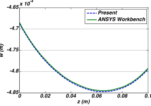
Furthermore, static analysis of a thick homogenous skew plate is also considered. The skew plate is fully clamped and subjected to a uniform pressure at its upper surface. The geometry and materi-al properties of the skew plate are considered as: h=0.1 m, a=0.5 m, b=1 m, φ=30°, E=E0=70
Gpa, �=0.3, P= 20 MPa at top surface
The through- the- thickness lateral deflection of central section of skew plate is obtained and compared with result of commercial FEM software ANSYS Workbench, as shown in Figure 4. Comparison between the results shows good agreement.
Figure 4 A comparison between through-the-thickness distributions of the lateral deflection of the central section of the homogeneous skew plate predicted by present results and ANSYS Workbench software
4.2 Static analysis
An FGM skew plate stands with sides a=0.5 m, b=1 m and thickness h = 0.1m. The material properties vary through thickness direction according to an exponential material gradation provi-ded in Eq. (1) with E0 = 70 (GPa). The plate is subjected to a uniform pressure loading P in the
z–direction on its top surface, while fully clamped edges is considered. The static pressure is taken as P = 20 MPa. Number of graded elements through the x, y and z directions are obtained 12*24*7, according to a mesh sensitivity study to obtain an accurate solution with a mesh that is sufficiently dense and not overly demanding of computing resources. Table 1 shows the conver-gence study of the normal stress �!! of the center point of the fully clamped FGM skew plate for
φ=20° and n=1. This table shows that the maximum discrepancy for graded elements is about 1.95 % while this value for homogenous type is about 7.23 %. It can be deduced that for the ho-mogenous elements, the results based on mesh convergence study need much more elements in comparison with graded elements one.
0
0.02
0.04
0.06
0.08
0.1
-4.85
-4.8
-4.75
-4.7
-4.65
x 10
-4
z (m)
w
(m
)
Present
φ=20° and n=1
Number of graded
elements 12*24*4 12*24*5 12*24*6 12*24*7
�!! (MPa) 16.14 (1.95 %) 15.98 (0.948 %) 15.9 (0.44 %) 15.83
Number of homogenous
elements 12*24*4 12*24*5 12*24*6 12*24*7
�!! (MPa) 16.97 (7.23 %) 16.64 (5.13 %) 16.31 (3.04 %) 16.11 (1.77 %)
Through-the-thickness distribution of the transverse deflection of the central section (�=!
!+
!
!
��� � ,�=!!) of the FGM skew plate is shown in Fig. 5 for different material gradient
index n = 1, 3 and 5 (the skew angle kept fixed φ=20°). As it may be deduced that deflections increases as n increases from n=1 to 5. This is because that, by increasing the material gradient index, the stiffness of the skew plate is decreased. furthermore, it may be concluded that no mat-ter to what value the mamat-terial property index, the magnitude of transverse deflection in bottom surface are lower in comparison with those developed in the top one. This behavior is because that the FGM plate is analyzed by three-dimensional theory of elasticity, therefore, the transverse compressibility of the plate is considered.
Figure 5 Through-the-thickness distribution of the transverse deflection of the central section of the skew plate for different grading exponent and �=20°
Figs. 6 and 7 illustrate through-thickness distribution of the in-plane normal and shear stres-ses of the central section of the FGM skew plate for different material gradient index n = 1, 3 and 5, respectively (φ=20°). According to latter discussion about lateral deflection, by increasing the material gradient index and consequently reducing the stiffness of plate the curvature of the plate increases. Therefore, as results shown in Figs.6 and 7, increasing the material property
in-0 0.02 0.04 0.06 0.08 0.1
-5 -4.8 -4.6 -4.4 -4.2 -4 -3.8 -3.6x 10
-4
z (m)
w
(m
)
dex leads to increase the in- plane normal and shear stress components, (
σ
xx
,
σ
xy) in the top andbottom surfaces. However, the resulting behavior is different through the thickness. Indeed, that is probably affected by the material nonlinearity of the FGM plate. Also, it may be deduced from results, the magnitude of in- plane normal and shear stress components in bottom surface are lower in comparison with those developed in top one regardless of what value material gradient index. This behavior is may be due to the curvature of the bottom surface is lower than the top one.
Figure 6 Through-the-thickness distribution of the normal stress �!!of the central section of the skew plate for different grading
exponent and �=20°
Figure 7 Through-the-thickness distribution of the shear stress �!"of the central section of the skew plate for different grading
exponent and �=20°
0 0.02 0.04 0.06 0.08 0.1
-2 -1.5 -1 -0.5 0 0.5
1x 10
8
z (m)
σx
x
(Pa
)
n=1 n=3 n=5
0 0.02 0.04 0.06 0.08 0.1
-2 -1 0 1 2 3 4x 10
7
z (m)
σx
y
(Pa
)
Effects of the skew angle on through thickness distribution of transverse deflection and in- plane normal and shear stress components of the central section of the FGM skew plate are depicted in Figs. 8 to 10 (n=3). It is observed that with increasing skew angle, the transverse deflection de-creases due to stiffening the plate involved with increasing the skew angle. On the other hand, with increasing skew angle there is an increase of in- plane shear stress component. It shows that increasing the skew angle is coupled to curvature growth. Furthermore, it is noticed that the ef-fect of skew angle on in- plane shear stress is more significantly in comparison with normal stress (σyy).
Figure 8 Through-the-thickness distribution of the transverse deflection of the central section of the skew plate for different skew angle and n=3
Figure 9 Through-the-thickness distribution of the normal stress �
!!of the central section of the skew plate for different skew angle
and n=3
0 0.02 0.04 0.06 0.08 0.1
-5.5 -5 -4.5 -4 -3.5
x 10-4
z (m)
w
(m
)
φ=10 φ=20 φ=30
0 0.02 0.04 0.06 0.08 0.1
-10 -5 0 5x 10
7
z (m) σ y
y
(Pa
)
Figure 10 Through-the-thickness distribution of the shear stress �!"of the central section of the skew plate for different skew angle
and n=3
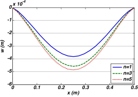
Distributions of the transverse deflection and the displacement component (u) of the mid-plane of the FGM skew plate are depicted along the horizontal axis (y=b/2, z=h/2) in Figs. 11 and 12 for different gradation exponents(φ=20°). As it may be noticed from results, both of
displace-ment components show identical behavior for n=1 to 3. But, displacement component u is de-creased for n=3 to 5. This is may be due to nonlinear behavior of the FGMs.
Figure 11 Distribution of transverse displacement at �=!!,�=!! for different grading exponent and �=20°
0 0.02 0.04 0.06 0.08 0.1 -4
-2 0 2 4 6x 10
7
z (m)
σ x
y
(Pa
)
φ=10
φ=20
φ=30
0 0.1 0.2 0.3 0.4 0.5
-6 -5 -4 -3 -2 -1
0x 10 -4
x (m)
w
(m
)
Figure 12 Distribution of displacement component u at �=!
!,�=
!
! for different grading exponent and �=
20°
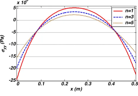
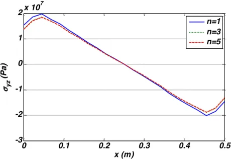
Variations of the in- plane normal stress and transverse shear stress components of the mid-plane of the skew plate are shown along the horizontal axis (y=b/2, z=h/2) in Figs. 13 and 14 for different gradation exponents (φ=20°). Results illustrated in Fig. 13 reveal that distribution of
the stress component σyy changes significantly depends on value of gradation exponent n.
However, this effect is not seen considerably in transverse shear stress (σyz), see Fig. 14.
Figure 13 Distribution of normal stress �!!at �=!!,�=!! for different grading exponent and �=20°
0 0.1 0.2 0.3 0.4 0.5
-2 -1 0 1 2x 10
x (m)
u
(m
)
n=1 n=3 n=5
0 0.1 0.2 0.3 0.4 0.5
-25 -20 -15 -10 -5 0 5
x 106
x (m)
σy
y
(Pa
)
Figure 14 Distribution of shear stress �!"at �=!!,�=!! for different grading exponent and �=20°
Distribution of the of the transverse deflection and the displacement component (u) of the mid-plane of the skew plate are shown along the horizontal axis (y=b/2, z=h/2) in Figs. 15 and 16 for various skew angles (n=3). The results indicate increasing the skew angle causes decrease both displacement components. As it has been discussed formerly with increase of skew angle, the displacement components decrease due to the stiffening of the plate involved with higher skew angle. According to the obtaining results, with increase of skew angle there is a decrease of in- plane normal stress component, see Fig.17. It could be concluded that unlike the effects of skew angle on distribution of stress through the thickness, increase in the skew angle leads to decrea-sing the in- plane stress component due to probably the plate tightened with higher skew angle. Finally, it can be seen from results of the stress components, both the through-thickness and lon-gitudinal distributions of the stress components have continuous variations due to using graded elements.
0 0.1 0.2 0.3 0.4 0.5
-3 -2 -1 0 1 2x 10
7
x (m) σ y
z
(Pa
)
Figure 15 Distribution of transverse displacement at �=! !,�=
!
! for different skew angle and grading exponent n=3
Figure 16 Distribution of displacement component u at �=! !,�=
!
!for different skew angle and grading exponent n=3
0 0.1 0.2 0.3 0.4 0.5
-6 -5 -4 -3 -2 -1
0x 10
x (m)
w
(m
)
φ=10 φ=20 φ=30
0 0.1 0.2 0.3 0.4 0.5
-2 -1 0 1 2x 10
-5
x (m)
u
(m
)
Figure 17 Distribution of normal stress �!! at �=! !,�=
!
! for different skew angle and grading exponentn=3 4.3 Dynamic Analysis
The skew FGM plate of the previous section is considered once again. As indicated before, the functionally graded plate consists of a mixture of ceramic at the bottom and metal at the top having the thickness ‘h’ considered in the present study. In order to obtain the effective proper-ties of FGM plate the Mori–Tanaka homogenization method is utilized. The material properproper-ties of the constituent materials are assumed to be Ec=380 (GPa), ρc=3800 (kg/m3) and Em=70
(GPa), ρm=2707 (kg/m3).
The numerical results presented in this section deal with the dynamic response of a fully clam-ped skew plate subjected to following uniformly distributed dynamic load at its top surface.
( )
00.005 ( )
0
0.005 ( )
p t
t
s
p t
t
s
≤
⎧
=
⎨
>
⎩
where
p
0 is supposed as 4 GPa/s during the analyses. The plate is unloaded in t=0.005 (s). As itmay be known, after the unloading, a transient vibration which is affected by the wave propaga-tion, reflection and interference would occur. The influence of various material properties, expo-nents and skew angles on dynamic response is presented and discussed in the subsequent para-graphs.
Fig. 18 indicates time history of the transverse deflection of the center point (� =!
!+ !
!
��� � ,�=!!, z=h/2) of the skew plate after the unloading for different gradation exponents (� =10°). The result shows that by increasing the gradation exponent, the volume fraction of the
ceramic phase increases and subsequently, the amplitude of the vibration decreases. Furthermore, the vibration frequency is increased with the material property exponent. It is because the plate is stiffened due to increasing the volume fraction index of the ceramic phase.
0 0.1 0.2 0.3 0.4 0.5
-4 -3 -2 -1 0 1
x 107
x (m) σx
x
(Pa
)
Figure 18 Time history of transverse deflection at �=! !
+! !
��� � ,�=!
!,�=
!
! for skew plate with �=
10° and for different
grading exponent
Figs. 19 to 22 show the time histories of the stress components σxx, σxy, σyz and σzz of the skew
plate center point (� =!
!+
!
! ��� � ,�=
!
!,�= !
!) for different gradation exponents and �=10°,
respectively. Results reveal that propagation of the stress waves following the unloading is affec-ted by the volume fraction index significantly. However, this influence is more considerable in time histories of transverse stress components. This is because the assumed FGM plate material properties vary only through the thickness. As a result, the behavior of transverse stresses is more correlated to magnitude of gradation exponent in comparison with that dependence of in- plane
stresses. As increasing volume fraction index causes increasing the plate stiffness, it may be
con-cluded from the obtained results for transverse stress components, stress wave propagation is more rapid in the higher index case, see Figs.21 and 22.
5 5.2 5.4 5.6 5.8 6
x 10-3 -4
-2 0 2 4x 10
-4
t (s)
w
(m
)
n=1
Figure 19Time history of normal stress �!! of the center point of the skew plate for different gradation exponents and �=10°
Figure 20 Time history of shear stress �
!" of the center point of the skew plate for different gradation exponents and �=10°
5.05 5.1 5.15 5.2 5.25
x 10-3 -4
-2 0 2 4 6x 10
7
t(s)
σ x
x
(Pa
)
n=1 n=3 n=5
5.05 5.1 5.15 5.2 5.25
x 10-3 -5
0 5x 10
6
t (s) σx
y
(Pa
)
Figure 21 Time history of shear stress �!"of the center point of the skew plate for different gradation exponents and �=10°
Figure 22 Time history of normal stress �
!! of the center point of the skew plate for different gradation exponents and �=10°
The effect of skew angle on time history of transverse deflection for the center point of the skew plate is shown in Fig.23. It could be observed that by increasing skew angle, amplitude de-crease and vibration frequency is inde-creased. It is because that the plate is stiffened due to higher skew angle.
5 5.1 5.2 5.3 5.4
x 10-3 -2
-1 0 1 2x 10
t (s)
σ y
z
(Pa
)
n=1 n=3 n=5
5.02
5.04
5.06
5.08
5.1
x 10
-3-2
-1
0
1
2
3
4
x 10
7
t (s)
σ
zz(Pa
)
Figure 23 Time history of transverse displacement of the center point of the skew plate for different skew angle and grading exponent n=1
The influence of various skew angles on time histories of stress components σxx, σxy, σzz and σzx,
is illustrated in Figs. 24 to 27. Results reveal that propagation of the stress waves subsequent the unloading is significantly affected by the skew angle. The skew plate mid-plane transverse deflec-tion for n=1 and � =30° at specified times after the unloading are shown in Figs. 28. These
figu-res show the vibration mode shapes of the FGM skew plate after the unloading.
Results denote that the propagation of stress waves after the unloading is strongly affected by the grading exponent and skew angle. The obtained results show that the use of a graded element has several advantages over the use of conventional elements in the dynamic and wave propaga-tion analyses. In convenpropaga-tional FE methods, continuous variapropaga-tions of the material properties are approximated by discrete and homogenous elements. Therefore, adjacent elements may have quite different isotropic material properties and severe discontinuity of the material properties is obser-ved in boundaries of these homogenous elements. As a result, creation of artificial wave reflections causes cumulative effects on magnitude and speed of the stress waves propagation. Therefore, by utilizing the graded elements in which the material properties vary continuously, enhanced accu-racy may be achieved without updating the mesh size.
5 5.2 5.4 5.6 5.8 6
x 10-3 -4
-2 0 2 4x 10
-4
t (s)
w
(m
)
Figure 24 Time history of normal stress �!!of the center point of the skew plate for different skew angle and grading exponent n=1
Figure 25 Time history of shear stress �!"of the center point of the skew plate for different skew angle and grading exponent n=1
5.05 5.1 5.15 5.2 5.25
x 10-3 -4
-2 0 2 4 6x 10
t (s)
σx
x
(Pa
)
φ=10 φ=20 φ=30
5.05 5.1 5.15 5.2 5.25
x 10-3 -1.5
-1 -0.5 0 0.5
1x 10
7
t (s) σ x
y
(Pa
)
Figure 26 Time history of normal stress �
!!of the center point of the skew plate for different skew angle and grading exponent n=1
Figure 27 Time history of shear stress �!"of the center point of the skew plate for different skew angle and grading exponent n=1
5.02 5.04 5.06 5.08 5.1
x 10-3
-2 -1 0 1 2
3x 10
7
t (s)
σ zz
(Pa
)
φ=10 φ=20 φ=30
5 5.1 5.2 5.3 5.4
x 10-3 -3
-2 -1 0 1 2 3x 10
7
t (s) σ x
z
(Pa
)
Figure 28 Mid-plane transverse deflection of skew plate for n=1 and �=30° after the unloading at t=5, 5.061, 5.072, 5.092, 5.103 and 5.22 (ms)
5 CONCLUSIONS
In the present paper, static and dynamic analyses of FGM skew plates are obtained based on the three–dimensional theory of elasticity. Graded elements, the principle of minimum energy, and Ray-leigh-Ritz energy method are utilized. By applying the three–dimensional graded elements for anal-ysis of the skew plates, discontinuities of the stress distribution that are present in the conventional
0 0.5 1 0 0.5 1 -2 -1.5 -1 -0.5 0
x 10-4
x (m) y(m) w (m ) 0 0.5 1 0 0.5 1 -10 -5 0 5
x 10-5
x (m) y (m) w (m ) 0 0.5 1 0 0.5 1 -6 -4 -2 0 2 4
x 10-5
x (m) y (m) w (m ) 0 0.5 1 0 0.5 1 -2 0 2 4 6 8
x 10-5
x (m) y (m) w (m ) 0 0.5 1 0 0.5 1 -5 0 5 10 15
x 10-5
x (m) y (m) w (m ) 0 0.5 1 0 0.5 1 -5 0 5 10
x 10-5
x (m) y (m)
w
(m
FE results, are eliminated. The results are obtained for various material grading index and different skew angles, thus showing the applicability of the present method. In the static analysis, the mate-rial properties vary through the thickness direction according to an exponential matemate-rial gradation and for the dynamic analyses, the effective material properties distribution of the FGM plate was determined using Mori–Tanaka homogenization technique. Results of present formulations are veri-fied by available results of a functionally graded rectangular plate for different boundary conditions and also compared with result of a fully clamped homogenous skew plate that obtained in ANSYS Workbench commercial FE software. The comparison between the results shows good agreement. It is observed that effect of skew angle is considerable on displacement components and stress wave propagation in static and dynamic analyses, respectively. It is because that increasing the skew angle is coupled to the plate stiffening. With certain modifications, the present research can be ex-tended for the analysis of arbitrary quadrilateral plates.
References
Akishev, N.I., Zakirov, I.I., Paimushin, V.N., Shishov, M.A., (2011). Approximate analytical solutions of stability problems for skew plates under combined loading. Russian Aeronautics 54: 115-124.
Asemi, K., Akhlaghi, M., Salehi, M., (2012). Dynamic analysis of thick short FGM cylinders. Meccanica 47: 1441-1453.
Ashrafi, H., Asemi, K., Shariyat, M., Salehi, M., (2013). Two–dimensional modeling of heterogeneous structures using graded finite element and boundary element methods. Meccanica 48: 663-680.
Bathe, K.J., Wilson, E.L., (1976). Numerical methods in finite element analysis. Prentice Hall Inc., Englewood Cliffs, New jersey.
Damanpack, A.R., Bodaghi, M., Ghassemi, H., Sayehbani, M., (2013). Boundary element method applied to the Bending Analysis of Thin Functionally Graded Plates. Latin American Journal of Solids and Structures 10: 549 – 570.
Das, D., Sahoo, P., Saha, K., (2008). Large-amplitude dynamic analysis of simply supported skew plates by a variational method. Journal of Sound and Vibration 313: 246-267.
Dey, P., Singha, M.K., (2006). Dynamic stability analysis of composite skew plates subjected to periodic in-plane load. Thin-Walled Structures 44: 937-942.
Ganapathi, M., Prakash, T., (2006). Thermal buckling of simply supported functionally graded skew plates. Composite Structures 74: 247-250.
Kiani, Y., Eslami, M.R., (2013). Thermomechanial Buckling of Temperature-dependent FGM Beams. Latin American Journal of Solids and Structures 10: 223-246.
Kim, J.H., Paulino, G.H., (2002). Isoparametric graded finite elements for nonhomogeneous isotropic and ortho-tropic materials. Journal of Applied Mechanics 69: 502–514.
Lee, S-Y., (2010). Finite element dynamic stability analysis of laminated composite skew plates containing cut-outs based on HSDT. Composites Science and Technology 70: 1249-1257.
Miyamoto, Y., Kaysser, W.A., Rabin, B.H., (1999). Functionally Graded Materials: Design, Processing and Ap-plications, Kluwer Academic Press, Netherlands, Dordrecht.
Ng, S.S.F., Lam, D.K.Y., (1985). Dynamic and static analysis of skew sandwich plates. Journal of Sound and Vi-bration 99: 393-401.
Park, T., Lee, S.-Y., Seo, J.W., Voyiadjis, G.Z., (2008). Structural dynamic behavior of skew sandwich plates with laminated composite faces. Composites Part B: Engineering 39: 316-326.
Prabhu, M.S.S., Durvasula, S., (1972). Stability of clamped skew plates. Applied Scientific Research 26: 255-271. Qing-qing, Z., (1991). Navier solution for the elastic equilibrium problems of anisotropic skew thin plate with var-iable thickness in nonlinear theories. Applied Mathematics and Mechanics 12: 373-382.
Ray, A.K., Banerjee, B., Bhattacharjee, B., (1994). Nonlinear analysis of skewed sandwich plates. Meccanica 29: 211-216.
Rezaei Mojdehi, A., Darvizeh, A., Basti, A., Rajabi, H., (2011). Three dimensional static and dynamic analysis of thick functionally graded plates by the meshless local Petrov–Galerkin (MLPG) method. Engineering Analysis with Boundary Elements 35: 1168–1180.
Sundararajan, N., Prakash, T., Ganapathi, M., (2005). Nonlinear free flexural vibrations of functionally graded rectangular and skew plates under thermal environments. Finite Elements in Analysis and Design 42: 152-168. Suresh, S., Mortensen, A., (1998). Functionally Graded Materials. Institute of Materials, IOM Communications, London.
Taj, G., (2013). Dynamic response of functionally graded skew shell panel. Latin American Journal of Solids and Structures 10: 1243 – 1266.
Upadhyay, A.K., Shukla, K.K., (2013). Geometrically nonlinear static and dynamic analysis of functionally grad-ed skew plates. Communications in Nonlinear Science and Numerical Simulation 18: 2252–2279.
Wu, G.Y., Shih, Y.S., (2006). Analysis of dynamic instability for arbitrarily laminated skew plates. Journal of Sound and Vibration 292: 315-340.
Xiang, Y., Kitipornchai, S., Liew, K.M., Lim, M.K., (1995). Vibration of stiffened skew Mindlin plates. Acta Me-chanica 112: 11-28.
Young, T.H., Lee, C.W., Chen, F.Y., (2002). Dynamic Stability of Skew Plates Subjected to Aerodynamic and Random In–plane Forces. Journal of Sound and Vibration 250: 401-414.
Zhang, Z., Paulino, G.H., (2007). Wave propagation and dynamic analysis of smoothly graded heterogeneous continua using graded finite elements. International Journal of Solids and Structures 44: 3601–3626.