Abs tract
This paper investigates the dynamic pull-in instability of vibrating micro-beams undergoing large deflection under electrosatically actuation. The governing equation of motion is derived based on the modified couple stress theory. Homotopy Perturbation Method is employed to produce the high accuracy approximate solution as well as the second-order frequency- amplitude relationship. The nonlinear governing equation of micro beam vibrations pre-deformed by an electric field includes both even and odd nonline-arities. The influences of basic non-dimensional parameters on the pull-in instability as well as the natural frequency are studied. It is demonstrated that two terms in series expansions are sufficient to produce high accuracy solution of the micro-structure. The accu-racy of proposed asymptotic approach is validated via numerical results. The phase portrait of the system exhibits periodic and homoclinic orbits.
Key words
Dynamic pull-in instability, Modified couple stress theory, Ho-motopy Perturbation Method, Frequency – amplitude relationship, Homoclinic orbit.
Dynamic pull-in instability of geometrically nonlinear
actuated micro-beams based on the modified couple
stress theory
1 INTRODUCTION
With development of modern technology, micro and nano-electro mechanical systems have shown enormous popularity on engineering and industry. The application of micro-electro-mechanical sys-tems (MEMS) devices especially the electrically actuated MEMS devices which require low actua-tion voltage levels are continuously growing. Actuated MEMS devices are extensively used in inkjet printers, switches, gyroscopes, chemo-sensors and so on. Recently several numerical and experi-mental studies have been conducted on the pull-in instability and dynamic behavior of MEMS de-vices (Ansari et al., 2013; Zhang and Fu, 2012; Rajabi and Ramezani, 2013; Nayfeh et al., 2005; He et al., 2009; Sedighi and Shirazi, 2013; Jia et al., 2011; Younis and Nayfeh, 2003; Mobki et al., 2013; Rahaeifard et al., 2013; Caruntu et al., 2013; Batra et al., 2008; Moghimi Zand and Ahmadian,
H am id M .Se d ig hi*, Ma zi ar C ha n -g iz ia n an d A m in re z a N o-gh re ha-b adi*
Department of Mechanical Engineering, Shahid Chamran University, Ahvaz, Iran
Received in 05 Mar 2013 In revised form 06 Aug 2013
2009; Nabian et al., 2013). However, the amplitude dependence of nonlinear frequency and pull-in instability has not been developed, till present.
A distributed size-dependent model based on the modified strain gradient elasticity theory (MSGT) was developed by Ansari et al. (2013)in order to investigate the pull-in instability of circu-lar microplates subjected to the uniform hydrostatic and non-uniform electrostatic actuations. They employed step by step linearization of the equation of motion and utilized the generalized differen-tial quadrature (GDQ) method to solve the problem numerically. A new model for a viscoelastic beam based on the simplified couple stress theory was developed by Zhang and Fu(2012). They investigated the effect of the beam size on the instantaneous pull-in voltage, durable pull-in voltage and pull-in delay time of the system. Rajabi and Ramezani (2013)studied the dynamic behaviour of the micro scale nonlinear beam model based on strain gradient elasticity. They demonstrated that by increasing the beam thickness, the strain gradient effect on increasing the natural frequency decreases and geometric nonlinearity plays the main role on its trend. Nayfeh et al. (2005) reviewed the development of reduced-order models (node and domain methods) for MEMS devices and dis-cussed the advantages and disadvantages of each implementation.
The improved macromodel of the fixed-fixed microbeam-based of MEMS capacitive switch was developed by He et al. (2009) to predict the electromechanical behaviors of electrically actuated MEMS capacitive switch. Their model accounted for moderately large deflections, dynamic loads, axial stress induced by the midplane stretching and the residual stress. Sedighi and Shirazi (2013) presented a new asymptotic procedure to predict the nonlinear vibrational behaviour of classical micro-beams pre-deformed by an electric field using Parameter expansion method. Jia et al. (2011) investigated the pull-in instability of micro-switches under the combined electrostatic and intermo-lecular forces. They accounted for the effect of axial residual stress, the force nonlinearity and geo-metric nonlinearity in their research and solved the governing equation using the differential quad-rature method.
Latin American Journal of Solids and Structures 11(2014) 810 – 825
the finite thickness of the microbeam. Moghimi Zand et al (2009) studied the dynamic pull-in in-stability of microbeams subjected to step voltages using homotopy analysis method under the con-sideration of electrostatic force and midplane stretching. Nabian et al. (2013) examined the stability of a functionally graded clamped-clamped micro-plate subjected to hydrostatic and electrostatic pressures and illustrated that the micro-system undergoes a saddle node and homoclinic bifurca-tions.
The current work intends to compute the second-order frequency-amplitude relation in a micro clamped-clamped beam due to electrostatic voltage. Recently, considerable progresses had been made in asymptotic approximate solutionsof nonlinear differential equations (Sedighi et al., 2013; Sedighi and Shirazi, 2012; Sedighi et al., 2012). There have been several approaches employed to solve the governing nonlinear differential equations to study the nonlinear vibrations such as Para-metrized Perturbation Method (PPM) (Barari et al., 2011), Energy Balance Method (Ghadimi et al., 2012), Variational Iteration Method and Hamiltonian Approach (HA)(Sedighi et al., 2012), Laplace Transform Method (Rafieipour et al., 2012), Max-Min Approach (He, 2008), Homotopy Analysis Method (HAM)(Sedighi et al., 2012), Parameter Expansion Method (Sedighi et al, 2012), Iteration Perturbation Method (IPM) (He, 2001) and Homotopy Perturbation Method (HPM) (He, 1999). It is well known that while the perturbation methods provide the most versatile tools for the nonlinear analysis of engineering problems, they have also some limitations. In order to overcome these drawbacks, combining the standard homotopy and the perturbation method, known as the Homotopy Perturbation Method (HPM), improves the drawbacks of both approaches. He (1999) developed the homotopy perturbation method for solving a variety of problems including the linear and the nonlinear as well as the initial and the boundary value problems by merging two aforemen-tioned techniques. Benefiting from easily computable components and rapid convergence, it has been applied to a wide class of functional equations.
The aim of the present article is to investigate the dynamic pull-in instability of geometrically nonlinear actuated micro-beams by introducing the second-order frequency amplitude relation. The nonlinear equation of motion is derived based on the modified couple stress theory using Hamilton’s principle. The effect of vibrational amplitude and system parameters on the pull-in instability and natural frequency is studied via HPM. In this direction, analytical expressions for vibrational re-sponse of actuated micro-beams are presented. The proposed analytical method demonstrates that two terms in series expansions is sufficient to obtain a highly accurate solution of micro-beam vi-bration.
2 MATHEMATICAL MODELING
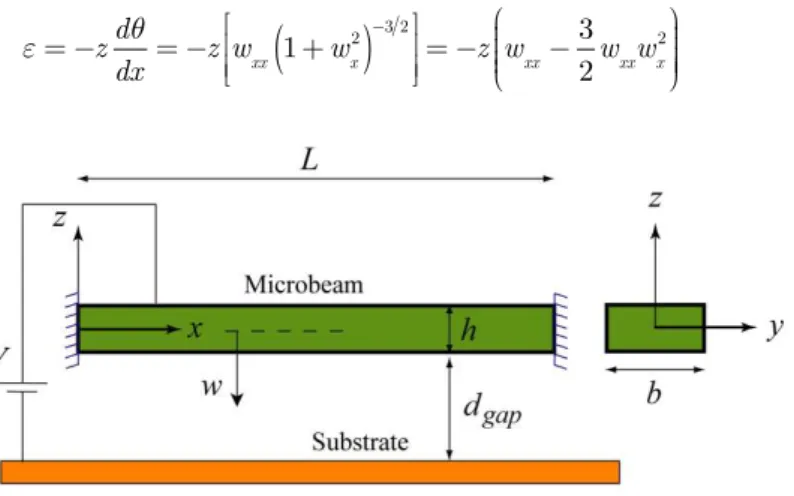
Consider a double-clamped micro-beam suspended above a rigid plate and under electro-statically actuation voltage as shown in Fig. 1.The actuated micro-beam has length L, cross section area A0,
height h, width b, densityr, moment of inertia I and modulus of elasticity E. The air initial gap
is dgap and an attractive electrostatic force which originates from voltage Vcauses the micro-beam
ε=−zdθ dx =−
z w
xx 1+wx 2
(
)
−3 2⎡ ⎣ ⎢ ⎢ ⎤ ⎦ ⎥
⎥=−z wxx−
3 2
w xxwx
2 ⎛ ⎝ ⎜⎜ ⎜⎜ ⎞ ⎠ ⎟⎟ ⎟⎟⎟ (1)
Figure 1 Configuration of a clamped-clamped actuated micro-beam
Taking into account the linear relation between the stress and strain, we have σ=Eε, The
strain energy of the micro-beam can be calculated from:
U = 1 2E
σ2dV V
∫
=E2 −z wxx−
3 2wxxwx
2 ⎛ ⎝ ⎜⎜ ⎜⎜ ⎞ ⎠ ⎟⎟⎟ ⎟⎟ ⎛ ⎝ ⎜⎜ ⎜⎜ ⎞ ⎠ ⎟⎟⎟ ⎟⎟ 2 dV V
∫
(2)Furthermore, the strain energy of an elastic continuum medium using the modified couple stress theory (MCST) can be mentioned as (Rahaeifard et al., 2013):
U MCST= 1 2 µ l2 w xx 2 dV V
∫
=12 µ A 0l 2 w xx 2 dx 0 L
∫
(3)whereµ represents the shear modulus and l denotes the material length scale parameter, using the
descriptions:
A
0 = dA A
∫
, I= z2dA A∫
(4)The total strain energy of the micro-structure incorporating the MCST micro-beam model can be expressed as:
U tot= EI 2 w xx− 3 2 w xxwx
2 ⎡ ⎣ ⎢ ⎢ ⎤ ⎦ ⎥ ⎥ 2 dx 0 L
∫
+µA 0l 2 2 w xx 2 dx 0 L
∫
(5)The virtual work Wperformed by the axial and electrical forces incorporating the von Karman
Latin American Journal of Solids and Structures 11(2014) 810 – 825
W =−1 2
N
i+
EA
2L wx
2 dx 0 L
∫
⎛ ⎝ ⎜⎜ ⎜⎜⎜ ⎞ ⎠ ⎟⎟⎟ ⎟⎟⎟w x 2 dx 0 L∫
− Fesw dx
0
L
∫
(6)whereN
i is the axial force and Fes is the electrostatic force per unit length of the micro beam which is described by(Moghimi Zand et al, 2009):
F
es=
bεV2
2 d
gap−w
(
)
2 1+βd
gap−w
b ⎛ ⎝ ⎜⎜ ⎜⎜⎜ ⎞ ⎠ ⎟⎟ ⎟⎟ ⎟⎟ (7)
whereb=0.65for double-clamped micro-beam. The kinetic energy is obtained as follows
T=ρA0
2 w t 2 dx 0 L
∫
(8)Applying the Hamilton’s principle leads to:
δ T−U
tot+W
(
)
dtt 1 t 2
∫
⎛ ⎝ ⎜⎜ ⎜⎜ ⎜⎜ ⎞ ⎠ ⎟⎟⎟⎟⎟⎟⎟=0 (9)
After some mathematical computations, the nonlinear governing equation of motion for actuated MCST micro-beam model is expressed as follows:
ρA
0wtt+EI wxxxx−3wxxxxwx 2
−3w xx 3
−12w xxwxwxxx
(
)
+µA0l 2
w
xxxx− Ni+ EA 0 2L w x 2 dx 0 L
∫
⎛ ⎝ ⎜⎜ ⎜⎜⎜ ⎞ ⎠ ⎟⎟⎟ ⎟⎟⎟wxx−Fes =0 (10)
By introducing the dimensionless parameters as:
τ= EI
ρbhL4t, W = w dgap,ξ=
x L, α=6
d gap h ⎛ ⎝ ⎜⎜ ⎜⎜⎜ ⎞ ⎠ ⎟⎟ ⎟⎟ ⎟⎟ 2 ,V2
=24εL 4
V2 Eh3
d
gap
3 ,fi=
NiL2
EI ,
γ=dgap
b ,µs=
12µ
E h l
( )
2,κ= dgap
L ⎛ ⎝ ⎜⎜ ⎜⎜⎜ ⎞ ⎠ ⎟⎟ ⎟⎟ ⎟⎟ 2 (11)
∂2
W
∂τ2 +⎡⎣⎢1+µs⎤⎦⎥
∂4
W ∂ξ4 −3κ
∂4 W ∂ξ4 ∂W ∂ξ ⎛ ⎝ ⎜⎜ ⎜⎜ ⎞ ⎠ ⎟⎟⎟ ⎟⎟ 2 + ∂ 2 W ∂ξ2 ⎛ ⎝ ⎜⎜ ⎜⎜ ⎞ ⎠ ⎟⎟⎟ ⎟⎟ 3
+4∂
2 W ∂ξ2 ∂3 W ∂ξ3 ∂W ∂ξ ⎛ ⎝ ⎜⎜ ⎜⎜ ⎜⎜ ⎞ ⎠ ⎟⎟⎟ ⎟⎟⎟ ⎟
− fi+α ∂W ∂ξ ⎛ ⎝ ⎜⎜ ⎜⎜ ⎞ ⎠ ⎟⎟⎟ ⎟⎟ 2 dξ 0 1
∫
⎛ ⎝ ⎜⎜ ⎜⎜ ⎜⎜ ⎞ ⎠ ⎟⎟⎟ ⎟⎟⎟⎟∂ 2 W ∂ξ2 −V2
4 1
(
−W)
2
(
1+γβ(
1−W)
)
=0(12)
Using Taylor expansion for electrostatic force in equation (12) results in
∂2
W
∂τ2 +⎡⎣⎢1+µs⎤⎦⎥
∂4
W ∂ξ4 −3κ
∂4 W ∂ξ4 ∂W ∂ξ ⎛ ⎝ ⎜⎜ ⎜⎜ ⎞ ⎠ ⎟⎟⎟ ⎟ 2 + ∂ 2 W ∂ξ2 ⎛ ⎝ ⎜⎜ ⎜⎜ ⎞ ⎠ ⎟⎟⎟ ⎟⎟ 3
+4∂ 2 W ∂ξ2 ∂3 W ∂ξ3 ∂W ∂ξ ⎛ ⎝ ⎜⎜ ⎜⎜ ⎜⎜ ⎞ ⎠ ⎟⎟⎟ ⎟⎟⎟⎟
− fi+α ∂W ∂ξ ⎛ ⎝ ⎜⎜ ⎜⎜ ⎞ ⎠ ⎟⎟⎟ ⎟ 2 dξ 0 1
∫
⎛ ⎝ ⎜⎜ ⎜⎜ ⎜⎜ ⎞ ⎠ ⎟⎟⎟ ⎟⎟⎟⎟∂ 2 W ∂ξ2 −V2
4 n+
1+γβ
(
)
Wnn=0
∞
∑
=0(13)
Assuming W
( )
ξ,τ =q( )
τ φ ξ( )
, where φ ξ( )
is the first eigen mode of the clamped-clamped beamand can be expressed as:
( )
(
)
(
)
( )
( )
( )
( )
(
(
)
(
)
)
cosh cos
cosh cos sinh sin
sinh sin
cc cc
cc cc cc cc
cc cc
l l
f x l x l x l x l x
l l
‐
= ‐ ‐ ‐
‐ (14)
where λ cc =
4.73 is the root of characteristic equation for first eigen mode. Applying the Bubnov-Galerkin decomposition method, the non-dimensional nonlinear governing equation of motion can be written as follows:
d2 q
dτ2+β1q
( )
τ + β2(
q( )
τ)
2+β
3
(
q( )
τ)
3+β
4
(
q( )
τ)
4 +β 0 ⎡ ⎣ ⎢ ⎢ ⎤ ⎦ ⎥⎥=0 (15)
where the parameters β0,...,β4 have been described in the Appendix.
3 BASIC IDEA OF HOMOTOPY PERTURBATION METHOD
Consider the following nonlinear differential equation (He, 1999):
A u
( )
−f r( )
=0, r∈ Ω (16)subjected to the following boundary condition:
B u,∂u
∂t ⎛ ⎝ ⎜⎜ ⎜⎜ ⎞ ⎠ ⎟⎟
Latin American Journal of Solids and Structures 11(2014) 810 – 825
where Ais a general differential operator, B a boundary operator, f r
( )
is a known analyticalfunction, Γis the boundary of the solution domain (Ω), and ∂u ∂tdenotes differentiation along
the outwards normal to Γ. Generally, the operator A may be divided into two parts: a linear part
L and a nonlinear one N. Therefore, Eq. (16) may be rewritten as follows:
( )
( )
( )
0L x +N x ‐ f r = (18)
In cases where the nonlinear Eq. (16) includes no small parameter, one may construct the follow-ing homotopy equation
H
( )
ν,p =(
1−p)
⎡L( )
ν −L u( )
0⎣⎢ ⎦⎥⎤+p A⎡⎣⎢
( )
ν −f r( )
⎤⎦⎥=0 (19)In Eq. (19), p∈⎡⎣⎢0,1⎤⎦⎥is an embedding parameter and u0 is the first approximation that satisfies
the boundary condition. One may assume that solution of Eq. (19) may be written as a power series inp, as the following:
ν=ν0+pν1+p2ν2+... (20)
The homotopy parameter pis also used to expand the square of the unknown angular frequency
as follows:
ω
0=ω 2
−pω1−p 2
ω
2−... (21)
where ω
0 is the coefficient of u
( )
r in Eq. (16) and should be substituted for the right hand side ofEq. (19). Besides, ω
i
(
i=1, 2, 3,...)
are unknown parameters. The best approximations for the solution and the angular frequency ω areu=lim
p→1ν=ν0+ν1+ν2+... (22)
ω2 =ω
0+ω1+ω2+... (23)
Now we apply the homotopy perturbation method on Eq. (15). We construct a homotopy in the following form:
H q
( )
,p =(
1−p)
⎡q+β1q⎣⎢ ⎤⎦⎥+pq+β1q+β2q 2
+β3q3+β4q4+β0
⎡
⎣⎢ ⎤⎦⎥=0 (24)
According to the HPM, we assume that the solution of Eq. (24) can be expressed in a series of
q
( )
τ =q0( )
τ +pq1( )
τ +p2q2( )
τ +... (25)the coefficient of q is expanded into a series in p in a similar way (He, 1999):
β1=ω2−
pω1−p2ω2+... (26)
After substituting Eq. (26) and Eq. (25) into Eq. (24), and rearranging based on powers of p
-terms, we have:
p0 :q
0
( )
τ +ω 2q0
( )
τ =0, q0( )
0 =A, q0
( )
0 =0 (27-a)p1:q1
( )
τ +ω2q1( )
τ =ω1q0( )
τ −β2(
q0( )
τ)
2+β3
(
q0( )
τ)
3+β4
(
q0( )
τ)
4+β0 ⎡ ⎣ ⎢ ⎢ ⎤ ⎦ ⎥
⎥, q1
( )
0 =0, q1( )
0 =0 (27-b)p2: q2
( )
τ +ω2q2( )
τ =ω1q1( )
τ +ω2q0( )
τ − 2β2q0( )
τ q1( )
τ +3β3(
q0( )
τ)
2q1
( )
τ +4β4(
q0( )
τ)
3q1
( )
τ ⎡ ⎣ ⎢ ⎢ ⎤ ⎦ ⎥ ⎥−β2
(
q0( )
τ)
2+β3
(
q0( )
τ)
3+β4
(
q0( )
τ)
4+β0 ⎡ ⎣ ⎢ ⎢ ⎤ ⎦ ⎥
⎥, q2
( )
0 =0, q2( )
0 =0(27-c)
Since the solution of Eq. (27-a) isq0 =Acos
( )
ωτ , the solution of Eq. (27-b) should not containthe so-called secular termcos
( )
ωτ . Substitution of this result into the right-hand side of equation(27-b) yields:
q1
( )
τ +ω2q1
( )
τ = ω 1A−3 4β3A
3 ⎛ ⎝ ⎜⎜ ⎜⎜ ⎞ ⎠ ⎟⎟
⎟⎟cos
( )
ωτ + −12β4A 4
−1
2β2A 2 ⎛ ⎝ ⎜⎜ ⎜⎜ ⎞ ⎠ ⎟⎟
⎟⎟cos 2
(
ωτ)
−1
2β2A 2
−3
8β4A 4
−1
4β3A 3
cos 3
(
ωτ)
−β 0−1 8β4A
4
cos 4
(
ωτ)
,(28)
No secular terms in q
1
( )
τ require eliminating contributions proportional to cos( )
wt on theright-hand side of equation (28), we have:
ω1=
3
4β3A 2
(29)
Solving equation (28) for
( )
1
q t gives the following second order approximation for q
( )
τ as:q1
( )
τ =cos
(
ωτ)
48β 4A4
+160β
2A 2
−15β 3A
3
+480β
0
(
)
480ω2 +
cos 2
(
ωτ)
80β 4A4
+80β
2A 2
(
)
480ω2
+β3A
3
cos 3
(
ωτ)
32ω2 +
β4A4cos 4
(
ωτ)
120ω2 +
−480β0−180β4A4
−240β2A2
480ω2
Latin American Journal of Solids and Structures 11(2014) 810 – 825
equation (26) for two terms approximation of series respect to p and for p=1 yields:
ω2=ω2−β
1−ω1 (31)
substitution of this result into the right-hand side of equation (27-c) for q
2
( )
τ and eliminating thesecular terms proportional to cos
( )
ωτ results in:S
( )
ω =−5 6β22A3
−7 4β4β2
A5
+1
2β3β2 A4
+3
2β3β0 A2
−63 80β4
2A7
+ 3
10β3β4 A6
+β1Aω
2
−2β2β0A+
3
4β3 A3
ω2
− 3 128β3
2A5
−3β4β0A 3
−Aω4
=0
(32)
solving equation (32) for the fundamental frequency gives the following second-order frequency-amplitude relationship for actuated micro-beam vibrations as:
ω
( )
A = β12 +
3
8β3A
2
+ β1
2
4 +
3β
1β3A 2 8 + 15β 3 2 A4 128 − 7β
2β4A 4
4 +
β2β3A 3
2 +
3β
0β3A
2 − 5β 2 2 A2 6 ⎛ ⎝ ⎜⎜ ⎜⎜ ⎡ ⎣ ⎢ ⎢ ⎢
+3β3β4A 5
10 −
3β4β0A 2
−63β4 2
A6
80 −
2β2β0
⎞
⎠ ⎟⎟ ⎟⎟⎟
1 2⎤
⎦ ⎥ ⎥ ⎥ ⎥
1 2 (33)
4 RESULTS AND DISCUSSION
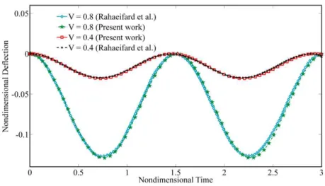
In order to verify the effectiveness of the present modeling and the approximate approach, the ob-tained results in this work are compared with the results of Rahaeifard et al. (2013) for micro-cantilever beam vibrations. As can be seen in Fig. 2, the second order approximation for q( )t based
on the modified couple stress theory exhibits an excellent agreement with the results obtained by Rahaeifard et al. (2013)using a hybrid finite difference method. It should be noted that in order to achieve the best second-order approximation with zero initial conditions, q0
( )
τ =1−cos( )
ωτ isFigure 2 Comparison of the approximate periodic solutions with the reported results by Rahaeifard et al. (2013)
The effect of normalized parameters on the natural frequency and pull-in instability of actuated clamped-clamped micro-beams have been illustrated in Figs. 3 to10. Fig.3 shows the characteristic curves of natural frequency for a micro-beam as a function of V under some assigned values of
normalized amplitudeA. It is demonstrated that this non-dimensional parameter has a significant
effect on predicting the pull-in phenomenon. It is obvious from Fig. 3 that by increasing the initial amplitude, the pull-in instability occurs at the lower values of actuation parameter V . In addition,
it is found that, the fundamental frequency of actuated micro-beam decreases by increasing the applied voltage until the natural frequency vanishes and the micro-beam drops to the rigid plate.
Figure 3 The effect of actuation parameter V on the fundamenal frequency of micro-beam
Fig.4 examines how the nonlinear fundamental frequency of actuated micro-beam is affected by the axial force parameterf
i. As can be observed, the fundamental frequency increases by decreasing
Latin American Journal of Solids and Structures 11(2014) 810 – 825
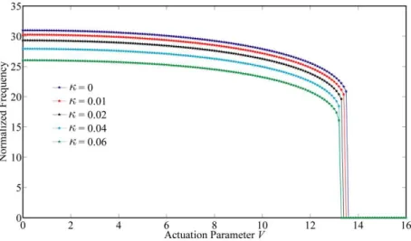
pull-in instability occurs at the lower values of parameterfi. Furthermore, pull-in phenomenon van-ishes by increasing the non-dimensional parameter fi. The influence of nonlinearity parameter κ on the fundamental frequency is investigated in Fig. 5. According to the illustrated results, it is obvi-ous that the fundamental frequency decreases as the parameter κincreases. Moreover, the pull-in
voltage shifts downward by increasing this parameter.
Figure 4 The effect of axial force parameter fi on the natural frequency of micro-beam
Figure 5 The effect of nonlinearity parameter k on the natural frequency of micro-beam
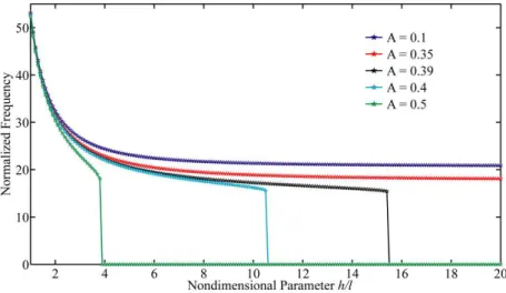
Fig. 6 represents the impact of length scale parameter h l on the pull-in instability of
micro-systems. It is clear from the Fig. that,when the beam thickness is in order of the material length scale, the normalized amplitude has no significant effect on the pull-in behavior of the structure. The fundamental frequency decreases by increasing the length scale parameter. In addition, as the initial condition increases, pull-in phenomenon occurs at lower values of non-dimensional parameter
the pull-in behavior of the system. To this end, the effects of these parameters on the dynamic be-havior of micro-beams are studied by plotting the time history and phase portrait diagrams. Figs. 7 and 8 investigate the nonlinear behavior of the system as a function of initial condition A.It is concluded that the time period of oscillation increases by increasing the normalized amplitude. In the vicinity of pull-in point (here A=0.65), a small increase in the amplitude, changes the
dynam-ic behavior of mdynam-icro-system. In this situation, when the initial amplitude increases, the system loses its stability and drops to the substrate beyond the pull-in point. According to Figs. 9 and 10, at less values of actuation voltage, the system exhibits periodic motion around the stable center point in the phase plane. Before pull-in point, when the actuation parameter increases, time period of vibra-tion increases. As the actuavibra-tion parameter approaches to the pull-in voltage (here V =19.35), the
motion trajectories in the phase plane approach to the unstable saddle node. There exists homo-clinicorbit which starts from the unstable branch and goes back to the saddle node at the stable one. By increasing the applied voltage and above the pull-in voltage, the micro-beam becomes dy-namically unstable and collapse onto the rigid plate.
Figure 6 The effect of ratio h l on the nonlinear frequency of actuated micro-beam
Latin American Journal of Solids and Structures 11(2014) 810 – 825
Figure 8 Phase portrait of micro-beam vibration for different values of initial amplitude A
Figure 9 Time history of micro-beam deflection for different values of applied voltage V
4 CONCLUDING REMARKS
In this research, the Homotopy Perturbation Method was employed to solve governing equation of geometrically nonlinear actuated micro-beams based on the modified couple stress theory. An excel-lent analytical solution using asymptotic approach was obtained. The integrity of the obtained ana-lytical solutions is verified in comparison with the results in the literature. The presented results showed thatas the normalized amplitude increases, the pull-in phenomenon occurs at lower values of actuation voltage. In addition, the pull-in stability disappears by increasing the axial force pa-rameter. The phase plane portrait of the system illustrated the periodic orbits around the stable center point and homoclinic orbit near the unstable saddle node.
References
Ansari, R., Gholami, R., Mohammadi, V., FaghihShojaei, M., (2013). Size-Dependent Pull-In Instability of Hy-drostatically and Electrostatically Actuated Circular Microplates, Journal of Computational and Nonlinear Dy-namics, Vol. 8, 021015, doi: 10.1115/1.4007358.
Barari, A., Kaliji, H.D., Ghadimi, M., Domairry, G., (2011).Non-linear vibration of Euler-Bernoulli beams, Latin American Journal of Solids and Structures, Vol. 8, pp. 139-148.
Batra, R.C., Porfiri, M., Spinello, D., (2008). Vibrations of narrow microbeams predeformed by an electric field, Journal of Sound and Vibration, Vol. 309, pp. 600–612.
Caruntu, D.I., Martinez, I., Knecht, M.W., (2013). Reduced Order Model Analysis of Frequency Response of Al-ternating Current Near Half Natural Frequency Electrostatically Actuated MEMS Cantilevers, Journal of Com-putational and Nonlinear Dynamics, Vol. 8, 031011, DOI: 10.1115/1.4023164.
Ghadimi, M., Barari, A., Kaliji, H.D., Domairry, G., (2012).Periodic solutions for highly nonlinear oscillation sys-tems, Archives of Civil and Mechanical Engineering, 12(3), pp. 389–395.
He, J.H., (2008).Max-Min approach to nonlinear oscillators. International Journal of Nonlinear Sciences and Nu-merical Simulation, Vol. 9, pp. 207-210.
He, J.H., (2001).Iteration perturbation method for strongly nonlinear oscillations, J. Vib.Control, Vol. 7, pp. 631– 642, http://dx.doi.org/10.1177/107754630100700501.
He, J.H. (1999).Homotopy perturbation technique. Computer methods in applied mechanics and engineering, 178(3-4), 257-262.
He, X.J., Wu, Q., Wang, Y., Song, M.X., Yin, J.H., (2009). Numerical simulation and analysis of electrically ac-tuated microbeam-based MEMS capacitive switch, Microsyst. Technol., Vol. 15, pp. 301–307.
Jia, X.L., Yang, J., Kitipornchai, S., (2011). Pull-in instability of geometrically nonlinear micro-switches under electrostatic and Casimir forces, ActaMech, Vol. 218, pp. 161–174, DOI: 10.1007/s00707-010-0412-8.
Mobki, H., Rezazadeh, G., Sadeghi, M., Vakili-Tahami, F., Seyyed-Fakhrabadi, M., (2013). A comprehensive study of stability in an electro-statically actuated micro-beam, International Journal of Non-Linear Mechanics, Vol. 48, pp. 78–85.
MoghimiZand, M., Ahmadian, M.T. (2009). Application of homotopy analysis method in studying dynamic pull-in pull-instability of microsystems, Mech. Res. Commun., Vol. 36, pp. 851–858.
Latin American Journal of Solids and Structures 11(2014) 810 – 825 Nayfeh, A.H., Younis, M.I., Abdel-rahman, E.M., (2005). Reduced-Order Models for MEMS Applications, Non-linear Dynamics, Vol. 41, pp. 211–236.
Rafieipour, H., Lotfavar, A., Mansoori, M.H., (2012). New Analytical Approach to Nonlinear Behavior Study of Asymmetrically LCBs on Nonlinear Elastic Foundation under Steady Axial and Thermal Loading, Latin Ameri-can Journal of Solids and Structures, Vol. 9, pp. 531 – 545.
Rahaeifard, M., Ahmadian, M.T., Firoozbakhsh, K., (2013). Size-dependent dynamic behaviour of microcantile-vers under suddenly applied DC voltage, ProcIMechE Part C: J Mechanical Engineering Science, 10.1177/0954406213490376.
Rajabi, F., Ramezani, S., (2013).A nonlinear microbeam model based on the strain gradient elasticity theory, Ac-ta Mechanica Solida Sinica, Vol. 26(1), pp. 21-34.
Sedighi, H. M. and Shirazi, K. H. (2012). A new approach to analytical solution of cantilever beam vibration with nonlinear boundary condition. ASME Journal of Computational and Nonlinear Dynamics, Vol. 7(3), 034502, doi:10.1115/1.4005924.
Sedighi, H. M., Shirazi, K. H. and Zare, J. (2012). Novel Equivalent Function for Deadzone Nonlinearity: Ap-plied to Analytical Solution of Beam Vibration Using He’s Parameter Expanding Method. Latin American Jour-nal of Solids and Structures, Vol. 9, pp. 443–451.
Sedighi, H.M., Shirazi, K.H., Noghrehabadi, A., (2012). Application of Recent Powerful Analytical Approaches on the Non-Linear Vibration of Cantilever Beams, Application of Recent Powerful Analytical Approaches on the Non-Linear Vibration of Cantilever Beams, DOI 10.1515/ijnsns-2012-0030.
Sedighi, H. M., Shirazi, K. H. and Zare, J. (2012). An analytic solution of transversal oscillation of quintic non-linear beam with homotopy analysis method. International Journal of Non-Linear Mechanics, Vol. 47, pp. 777– 784.
Sedighi H. M., Shirazi K. H., Noghrehabadi A. R., Yildirim A. (2012). Asymptotic Investigation of Buckled Beam Nonlinear Vibration. Iranian Journal of Science and Technology, Transaction B. Engineering, in press. Sedighi, H. M., Shirazi, K. H., Reza, A. and Zare, J. (2012). Accurate modeling of preload discontinuity in the analytical approach of the nonlinear free vibration of beams. Proceedings of the Institution of Mechanical Engi-neers, Part C: Journal of Mechanical Engineering Science, doi:10.1177/0954406211435196.
Sedighi, H.M., Shirazi, K.H., Attarzadeh,M.A., (2013). A study on the quintic nonlinear beam vibrations using asymptotic approximate approaches, Acta Astronautica, Vol. 91, pp. 245-250, doi:10.1016/j.actaastro.2013.06.018.
Sedighi, H.M., Shirazi, K.H., (2013). Vibrations of micro-beams actuated by an electric field via Parameter Ex-pansion Method, Acta Astronautica, Vol. 85, pp. 19–24. Doi: 10.1016/j.actaastro.2012.11.014.
Younis, M. I., Nayfeh, A. H., (2003).A Study of the Nonlinear Response of a Resonant Microbeam to an Electric Actuation, Nonlinear Dynamics, Vol. 31, pp. 91–117.
Appendix
β1= 1+µ
s
⎡
⎣⎢ ⎤⎦⎥λcc
4
−f
i φφ′′dξ
0 1
∫
−λ2
4
2+γβ
(
)
β2=− λ2
4
3+γβ
(
)
φ3dξ
0 1
∫
β3=−
λ2
4
4+γβ
(
)
φ4dξ
0 1
∫
−α φφ′′ φ′2dξ
0 1
∫
⎡
⎣ ⎢ ⎢ ⎢
⎤
⎦ ⎥ ⎥ ⎥dξ
0 1
∫
⎛
⎝ ⎜⎜ ⎜⎜ ⎜
⎞
⎠ ⎟⎟⎟
⎟⎟⎟−3κ φ φ( )4φ′2
+φ′′3
+4φ′φ′′φ′′′
(
)
dξ0 1
∫
β4 =− λ2
4
5+γβ
(
)
φ5dξ
0 1
∫
β0=−
λ2 4
1+γβ
(
)
φdξ0 1