Sofia Amorim Almeida Chamiço
Licenciada em Engenharia de Micro e Nano TecnologiasDevelopment and characterization of
poly-meric membranes for electromechanical
actuation
Dissertação para Obtenção do Grau de Mestre em Engenharia de Micro e Nano Tecnologias
Orientador: Dra. Isabel Ferreira, Professora associada, FCT Co-orientador: Dra. Ana Batista, FCT
Júri
Presidente: Dr. Rodrigo Martins, Professor catedrático, FCT Arguente: Dr. João Paulo Borges, Professor auxiliar, FCT
Vogal: Dra. Isabel Ferreira, Professora associada, FCT
Development and characterization of polymeric membranes for electromechanical actua-tion
Copyright © Sofia Amorim Almeida Chamiço, Faculdade de Ciências e Tecnologia, Universi-dade Nova de Lisboa.
A Faculdade de Ciências e Tecnologia e a Universidade Nova de Lisboa têm o direito, perpétuo e sem limites geográficos, de arquivar e publicar esta dissertação através de exemplares impressos reproduzidos em papel ou de forma digital, ou por qualquer outro meio conhecido ou que venha a ser inventado, e de a divulgar através de repositórios científicos e de admitir a sua cópia e dis-tribuição com objetivos educacionais ou de investigação, não comerciais, desde que seja dado crédito ao autor e editor.
Agradecimentos
Por fim, a montanha russa da dissertação, que teve tantos pontos altos como baixos está a terminar, por isso gostaria de agradecer a todos os que de alguma forma contribuíram, não só durante os últimos meses, mas durante os 5 anos que passei na faculdade e os 3 do ensino secun-dário que me motivaram sempre a utilizar o meu potencial para tudo na vida.
Agradeço aos professores Dr. Rodrigo Martins e Dra. Elvira Fortunato por proporcionarem a oportunidade de estudar estes 5 anos num curso novo e inovador como o curso de Engenharia de Micro e Nanotecnologias.
À minha orientadora, Professora Dra. Isabel Ferreira por me ter dado a oportunidade de trabalhar com excelentes pessoas, formando um grande grupo unido de investigadores. À minha co-orienadora, Dra. Ana Batista, que mesmo grávida, esteve presente para me orientar da direção correta.
A todos os que me acompanharam no laboratório nos últimos meses e que de alguma forma contribuíram para o desenvolvimento desta dissertação. Obrigada Inês Rúpio, Paulo Duarte, Da-vid Magalhães, Joana Figueira, Catarina Bianchi e Joana Loureiro.
À Aninha, parceira nos crimes, por me aturar todos os dias com uma paciência de santa (santa só a paciência mesmo), sem ela não teria sido a mesma coisa. Por todos os conselhos, conversas, jantares e por uma amizade única e dinâmica que nos faz parecer rapazes. Não posso deixar de agradecer aos malucos, autistas que estiveram sempre presentes comigo nos últimos meses, tanto no laboratório como nas saídas para aliviar a tensão, Almeida, Andreia, Carolina, Gonçalo, Jaime e Gabriel.
Aos meus pais, João e Ester, que nos últimos 23 anos foram incansáveis para que nada me faltasse e por sempre me encorajarem, não a fazer o que eu sei melhor, mas a fazer o que mais gosto para ser uma grande pessoa e ter orgulho em tudo o que me proponha a fazer.
À minha avó Rosete pelos almoços e jantares em tempos difíceis de estudo. Ao meu avô Manuel por todo o seu conhecimento e cultura que estará sempre presente na minha vida. À minha avó Maria por ter cuidado de mim na minha fase mais chata, permitindo-me crescer passo a passo com os meus primos, tornando-os os meus melhores amigos.
A todos os meus tios, em especial à tia Madalena que me ensinou que a vida não é só estudar, há todo um mundo pronto para ser descoberto. À tia Lena por todo o apoio e conselhos dados, desde as cantorias aos 5 anos, até ao “Se há alguém que consegue és tu, só falta a tese”. Ao meu tio Paulo que me ensinou o valor de um coração de gelo nos momentos de maior tensão e sentimentalismo, que me permitiu ser mais racional quando confrontada com os obstáculos da vida pessoal e profissional. À Tita, que sempre me acompanhou em todos os pequenos momentos da vida, planeou as minhas primeiras grandes festas em casa e fez de tudo para me ver sempre com um sorrisão de orelha a orelha. À Tita e ao Pedro por terem o filho mais fofo de sempre, uma das maiores alegrias da minha vida, capaz de por todos de bom humor.
Aos meus irmãos, Dinis e Diana, por acreditares sempre em mim e virarem a casa do avesso. Sem vocês a minha vida seria muito mais pobre e não teria aprendido a importância de ser um modelo para as gerações futuras. Tudo o que vos ensinei, aprendi a dobrar, fazendo de mim uma melhor pessoa aos olhos do mundo. Aquilo que ponho em prática na minha vida foi
iv
antes testado em vocês, por isso um obrigado por aturarem as minhas parvoíces e monólogos inacabáveis.
Aos meus primos, em especial ao Gustavo, que mais que um primo é um irmão para mim, nada existe sem ti e foi bom poder partilhar cada atrofio e festa contigo desde sempre. Ao Diogo, companheiro de jogos, sempre disposto a melhorar o que é por ele próprio e nunca pelos outros.
Ao meu fofinho, por me aturar durante tanto tempo, que nem me lembro do tempo em que ele não existia na minha vida. Sem ele tudo era mais simples, mas sem nenhuma graça.
A todos os amigos que me acompanharam nesta jornada e tornaram a vida menos cinzenta. Às SEIS, que são quatro, por nunca desistirem desta amizade verdadeira e genuína, que nem o tempo, nem a distância pode quebrar. Obrigado pelo vosso “input” e vivencias que me ajudaram, não só na tese, como na vida.
Ao Zé Rui, Filipa, Ribas, Gonçalo e Ricardo, por me mostrarem que é importante nunca esquecer os nossos sonhos. Que o passado, não define o futuro e tudo o que fazemos ajuda a contruir a nossa personalidade.
Aos meus colegas de curso que sempre me proporcionaram grandes alegrias durante os últimos 5 anos. À sala 202 que juntou um grupo de estudantes a quem eu hoje chamo de amigos. Ao grupo praxista de NANO, por serem incansáveis e sempre presentes para integrar os novos alunos na vida académica, sendo a peça fundamental que me tornou o que sou hoje, tole-rante, pacifica e focada. Em especial aos meus afilhados que seguiram as minhas pisadas e me encheram de orgulho.
Financial Support
This work was possible due to the partial financing support of the following projects: H2020-ICT-2014-1, RIA, TransFlexTeg-645241; ERC-CoG-2014, ChapTherPV, 647596; and by FEDER funds through the COMPETE 2020 Program and National Funds through FCT - Portu-guese Foundation for Science and Technology under the project UID/CTM/50025/2013.
Resumo
A bioeletrónica é um campo de estudo ainda em desenvolvimento, criando promessas e entusi-asmo. Os materiais orgânicos quando comparados com os materiais da eletrónica tradicional apre-sentam melhor compatibilidade mecânica com os tecidos e também uma compatibilidade natural com substratos, mecanicamente, flexíveis.
Um desses materiais orgânicos, o PEDOT:PSS, tem emergido nos últimos anos, como o material de eleição em algumas aplicações, como por exemplo músculos artificiais e atuadores mecânicos para aplicações de lentes com auto focagem.
Este trabalho tem como objetivo a produção de membranas finas electroativas que sejam capazes de dobrar quando sujeitas a um determinado potencial elétrico, o estudo das suas propri-edades, tanto elétricas como mecânicas, o estudo da influencia de alguns parâmetros do processo e a investigação da durabilidade, confiabilidade e reprodutibilidade dos dispositivos eletromecâ-nicos. Os melhores resultados foram obtidos com o dispositivo composto por PEDOT:PSS e PVDF, exibindo uma atuação mecânica quando aplicado um campo elétrico entre os elétrodos do dispositivo, observando-se uma elongação máxima de mais de 40% apresentando valores de re-sistência mecânica à tensão de 40 MPa.
Palavras-chave: Bioeletrónica, Polímeros, PEDOT:PSS, Membranas eletroativas, Atua-dores
Abstract
Bioelectronics is a field still in development that will have a positive impact in individuals’ life worldwide creating promises and excitement. The organic materials “soft” nature offers better mechanical compatibility with tissue than traditional electronic materials, and have natural com-patibility with mechanically flexible substrates. One of those organic materials, PEDOT:PSS, has emerged in recent years as a champion material in some applications such as artificial muscles and as bending actuators for autofocus micro lens applications.
This work aims at the research and production of thin electroactive membranes that are able to bend at a when applying a certain electrical potential across it, the study of its electrical and mechanical properties, a study about the influence from the process parameters and the in-vestigation of the electromechanical devices durability, reliability and reproducibility. The elec-tromechanical device PEDOT:PSS/PVDF obtained the best results, showing a low voltage actu-ation, mechanical strength of 40 MPa.
List of Abbreviations
CA – Cellulose acetateCMC – Carboxilmethyl cellulose DCM - Dichloromethane
DMF – Dimethylformamide EAP – Electroactive polymer PANI - Polyaniline
PCL - polycaprolactone
PDADMAC – poly (diallyldimethylammonium chloride) solution PEDOT - poly(3,4-ethylenedioxythiophene)
PEDOT:PSS – poly(3,4-ethylenedioxythiophene) doped with poly (styrenesulfonate) PPy – polypyrrole
PS – polystyrene
PSS – poly (sodium 4-styrenesulfonate) PVDF – poly (vinylidene fluoride) PVP – poly(vinylpyrrolidone) SEM – scanning electron microscopy
List of Symbols
Al – aluminiumºC – degrees H2O – water I - current
KOH – potassium hydroxide L – length of the resistor l0 – initial displacement NaCl – Sodium Cloride min – Minutes
R – Resistance
RT – room temperature S – area of conductive layer V – Volt
σ – conductivity ɛ - strain
Índice Geral
Agradecimentos ... iii Resumo ... v Abstract ... vii List of Abbreviations ... ix List of Symbols ... xiÍndice Geral ... xiii
List of tables ... xv
List of figures ... xvii
1 Motivation and objectives... xix
1.1 Motivation ... xix
1.2 Objetives... xix
2 Introduction ... 1
2.1 State of the art ... 1
2.2 Electroactive polymer actuators ... 1
2.3 PEDOT:PSS ... 2
2.4 Applications ... 3
3 Materials and Methods ... 7
3.1 Thin film production ... 7
3.2 Polymeric films formation for passive layer ... 7
3.3 Conductivity measurement ... 8
3.4 Mechanical Tests ... 9
3.5 Bending tests ... 10
3.6 Electronic-stimuli ... 10
3.7 Structural and morphological characterization ... 11
4 Results and discussion ... 13
4.1 Preliminary study: selection of passive and active layers... 13
4.2 Electrical properties: Influence of layer thickness ... 14
4.3 Ionic conductivity of PVDF ... 16
4.4 Mechanical tests ... 17
4.5 Electronic-stimuli ... 19
5 Conclusions and future perspectives ... 29
5.1 Conclusions ... 29
5.2 Future perspectives ... 30
6 Bibliography ... 31
7 Annex ... 33
List of tables
Table 2.1: Some EAP companies and a list of several products under development in 2011 [6] . 5 Table 3.1: Materials and methods for producing the polymeric membranes. ... 8 Table 4.1: Study of several materials for passive and active layers with and without NaCl... 13 Table 4.2: Materials and its characterization regarding Young modulus, elongation at break and
maximum stress, using 10 samples for each material. ... 18 Table 4.3: Materials, sizes and results for the electrical bending tests using PEDOT:PSS as
List of figures
Figure 2.1: (a) Three-layer structure of the electromechanical actuators: the electroactive polymeric film was coated by two very thin metal electrodes required to apply the electric field. (b) Three-layer structure for an electro-chemo-mechanical actuator: an elastic polymer film tape is covered by two films of conducting polymer acting as reactive
electrodes (oxidation and reduction), in an electrolyte bath. Adapted from [2] ... 2
Figure 2.2: Ionomers present in the composition of PEDOT:PSS. ... 2
Figure 2.3: Bending conducting polymer actuator with PVDF as porous membrane and with PEDOT:PSS casting. In contact (the interfacial layer), the actuator has a high level of adhesion. Adapt from [9] ... 3
Figure 2.4: Photograph of the prototype of the robotic fish. [7] ... 3
Figure 2.5: The INTACTTM refreshable Braille screen under development by Quantum Technology, Australia.[12] ... 4
Figure 2.6: photograph of rehabilitation glove prototype. [13] ... 4
Figure 3.1: Materials for passive (grey) and active layer (blue) and actuator final form (middle schematic) [17-19]. ... 7
Figure 3.2: Schematic for the formation of PVDF films where a) PVDF, b) Magnetic agitation of PVDF with DMF and c) Film deposition in a substrate (glass) and heated at 110º for solvent evaporation. ... 7
Figure 3.3: a) Setup for IV curves measures; b) schematic of the actuator for conductivity calculations. ... 9
Figure 3.4: Layers and dimensions for planar conductivity measures. ... 9
Figure 3.5: Tensile strength apparatus used to perform mechanical strength tests on PVDF and PVDF/PEDOT:PSS samples. ... 10
Figure 3.6: Bending test apparatus controlled by Arduino and close-up in the sample connections for the bending test. ... 10
Figure 3.7: Experimental setup used to hold the actuator for the bending test. ... 11
Figure 4.1: Fused PEDOT:PSS deposition in CMC film. ... 14
Figure 4.2: Configuration of the device used for the tests. ... 14
Figure 4.3: PEDOT:PSS film thickness as a function of the PEDOT:PSS volume dropped in a 7.5 cmx2.5 cm substrate. ... 15
Figure 4.4: PEDOT:PSS conductivity as a function of the film thickness measured after film deposition and three weeks later. Top view SEM image of a sample. ... 15
Figure 4.5: PVDF conductivity variation with the film thickness right after film deposition and after three weeks. ... 16
Figure 4.6: Variation of conductivity versus applied frequency for PVDF film and PVDF film with 0.4 % of NaCl ... 17
Figure 4.7: Tensile test of one of the 10 samples of PVDF w/ NaCl. ... 18
Figure 4.8: Resistance variation along the cycles of the mechanical bending as well with the lower and higher limit of variation. ... 19
Figure 4.9: IV curve of the sample with 8 μm thickness of PEDOT:PSS and a) 24 μm thickness of PVDF, b) 25 μm thickness of PVDF with NaCl, c) 36 μm thickness of PVDF and d) 39 μm of PVDF. ... 20
Figure 4.10: Variation of the conductivity with the PVDF thickness, before and after electrical stimuli. ... 21
Figure 4.11: Variation of the planar conductivity with the PEDOT:PSS thickness before and after bending. ... 21
xviii
Figure 4.12: Transversal conductivity variation along the cycles with PVDF thickness of 24 μm, varying PEDOT:PSS thickness and NaCl concentration... 22 Figure 4.13: Raman spectra of: PEDOT:PSS before the electroactive bending with
polyelectrolyte (PSS) - black line; PEDOT:PSS before the electroactive bending - red line; PEDOT:PSS after electroactive bending - blue line. ... 26 Figure 4.14: FTIR spectrum of PEDOT:PSS before the electroactive bending with
polyelectrolyte (PSS) - red line; PEDOT:PSS before the electroactive bending - black line; PEDOT:PSS after electroactive bending - blue line. ... 27
1 Motivation and objectives
1.1 Motivation
The nature shows several examples of responsive stimuli materials such as mimosa leaves that collapse when touched, leaflets of codariocalyx motorius rotate under sunlight, sunflowers follow the sun, chameleons change colour according environment, and many others examples. The polymers are the ones most close to nature and their engineering have been proved the pos-sibility to mimic certain aspect of nature. Stimuli-responsive polymers can change their properties (configuration or physical properties) when submitted to appropriated stimuli: heat; water solu-tions; pH; electrical; light; magnetic field or solvent. Therefore, the development of electroactive devices based on polymers have attracted our interest and the one of many researchers in the world. The electrical control of a movement will open doors to mimic muscles, valves, smart textiles, among others. Due to a lack of development in this field at DCM-FCT/UNL our motiva-tion was to initiate this research field, to experiment some recipes from the state of the art and develop new ones.
1.2 Objetives
A polymeric device able to bend when submitted to electrical stimuli is the goal of this work. To achieve that, the materials that fulfil the requirements must be selected, these should be tested against proposed functionality to choose the correct device structure, the materials should be characterized to understand the influence of films’ thickness and the flexure as a function of voltage applied evaluated. For selecting the most suitable material as flexible substrate/mem-brane, several polymers (PVDF, PS, PVP) must be tested and selected for final device construc-tion and testing. For that, the work is subdivided in: film preparaconstruc-tion, electric and mechanical properties, processes parameters influence, and the electromechanical devices durability, reliabil-ity and reproducibilreliabil-ity.
2 Introduction
This chapter consists of a brief introduction on the state of the art, the electroactive polymer actuator, polymeric fibres as electromechanical actuators, PEDOT:PSS and previous and future applications.
2.1 State of the art
Bioelectronics is a field still in its infancy that become promising and exciting. The man/ robot interface is getting every day more importance. Up to recent years this interface has been metal/mechanical based, however the tendency it to mimic nature. Indeed, inside every living cell thousands of reactions occurs simultaneously. Some of those reactions are intramolecular and intermolecular interactions, exchanging ions and water with the surroundings. To try to mimic those reactions is required electrical currents, reactive (electrochemical) polymers and aqueous solutions. The electrochemistry of conducting polymers constitutes a reactive system able to re-produce reactions of biological functions. Organic electronic materials transport ions, have direct interfaces with electrolytes and can have the properties changed to fit the requirements of an application. [1-3]
In the past two decades, the increase of works in organic electronics led to big technological advances. The “soft” nature of organics offers better mechanical compatibility with tissue than traditional electronic materials, and have natural compatibility with mechanically flexible sub-strates. [4]
The development of new applications in this emerging technology has only one limitation, the materials. There is always something to be improved, response time, biocompatibility or de-gradability, for that purpose, the continuum search of new materials/devices never ends. Since polymeric actuators are macroscopic or microscopic devices that transduce energy from different sources into macroscopic mechanical energy by using polymer films, they became good at this new applications. [2,3,5]
2.2 Electroactive polymer actuators
Electroactive polymer (EAP) actuators are devices made of smart materials capable of a continuum deformation in response to electrical stimuli. When comparing EAP actuators with traditional actuation technologies such as electrostatic, electromagnetic, and piezoelectric, they show better functional and structural properties. The most important properties are large active strains in response to driving voltages, high power density, high mechanical compliance, struc-tural simplicity and versatility, scalability, no acoustic noise, and, in most cases, low costs. [6,7] There are two types of EAP actuators, ionic and electronic, based on their activation mech-anism. Electronic, or field activated EAPs are driven by Coulomb forces produced by the electric field that is created between the coating electrodes on the films, or by charge on a local scale.
2
This EAPs can be used for robotic applications since they can hold the displacement while acti-vated under a DC voltage. The response time is fast (<10-3 s), however, they require high activa-tion fields (>10 V/µm), close to the breakdown level. Ionic EAPs consists of two electrodes and an electrolyte in the middle, and the operation is based on the drifting and diffusion of ions, which will oxidise or reduces the film conducting polymers, changing the material composition. In con-trast to electronic EAPs, ionic EAPs require less than 3 V as actuation voltages, which is best for applications were power consumption is a concern. Their disadvantages are a need to maintain their low electromechanical coupling and wetness. Two different examples of structures are showed in figure 2.1, were (a) is an electronic EAP and (b) is an ionic EAP. [5,9]
Figure 2.1: (a) Three-layer structure of the electromechanical actuators: the electroactive polymeric film was coated by two very thin metal electrodes required to apply the electric field. (b) Three-layer structure for an electro-chemo-mechanical actuator: an elastic polymer film tape is covered by two films of conduct-ing polymer actconduct-ing as reactive electrodes (oxidation and reduction), in an electrolyte bath. Adapted from [2]
2.3 PEDOT:PSS
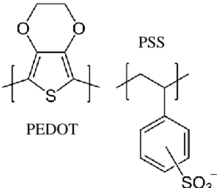
The conducting polymer poly(3,4-ethylenedioxythiophene) doped with polystyrene sul-fonate) (PEDOT:PSS), with a structure showed in figure 2.2 , has emerged in recent years as the most suitable material for several applications such as artificial muscles or bending actuators for autofocus micro lens applications. [2,6,10]
Figure 2.2: Ionomers present in the composition of PEDOT:PSS.
The big difference between this conducting polymer films and the others is that, there is no need to membranes be formed by electropolymerization or chemical polymerization. The ad-vantage of PEDOT is it less prone to oxidation or deterioration, however, in PEDOT/PSS-based bending actuators, we must ensure the strength of the interface between the PEDOT/PSS layer
PEDOT
and the electrolyte membrane to achieve the necessary durability. PEDOT/PSS is usually formed by casting (such as drop casting and film casting). One of the actuators layouts used is the one demonstrated in figure 2.3. [10,11]
It can also be used as a transparent, conductive polymer with high ductility as an antistatic agent to prevent electrostatic discharges during films production, and as an electrolyte in polymer electrolytic capacitors.
Figure 2.3: Bending conducting polymer actuator with PVDF as porous membrane and with PEDOT:PSS casting. In contact (the interfacial layer), the actuator has a high level of adhesion. Adapt from [9]
2.4 Applications
A set of representative applications are given in the following. These were chosen accord-ing structure's similarity or containaccord-ing the family materials of those used in this thesis.
Robotic fish tail controlled remotely
Composed of three main layers: two conducting PPy layers and an inner porous separator of poly (vinylidene fluoride) (PVDF) that holds the liquid electrolyte, exhibits a simple bending motion like a bilayer cantilever that can be used for propulsion in a robotic fish, such as the one in figure 2.4. [7,12]
Figure 2.4: Photograph of the prototype of the robotic fish. [7]
Electronic Braille Screen
4
of text (up to 80 characters). Quantum Technology in Australia proposed one where is possible, by the use of axial actuators that sit below each dot and act in the vertical direction by axial contraction and expansion, to have a response time of less than 0.5 sec. This actuators are made with Ppy and ionic liquid. [12]
Figure 2.5: The INTACTTM refreshable Braille screen under development by Quantum Technology,
Aus-tralia.[12]
Rehabilitation glove
Figure 2.6: photograph of rehabilitation glove prototype. [13]
For the actuators in the glove, and according Geoffrey Spinks and others, is being studied several components, but it’s emphasised polypyrrole and carbon nanotubes composites. The most difficult objective to uphold is doing different actuators for each phalange joint, hence the tendon movement is different. [13]
Table 2.1: Some EAP companies and a list of several products under development in 2011 [6]
Company EAP class Example of products Country
Artificial Muscle Dielectric elastomers Haptic systems, pumps, valves, autofocus-lens posi-tioners, acoustic speakers
USA
Danfoss PolyPower Eamex
Dielectric elastomers Conjugated poly-mers, Ionic polymer– metal composites
Silicone films and linear actu-ators
Autofocus camera modules, pumps, entertainment gadgets
Denmark Japan
Environmental Ro-bots
Polymer gels, Ionic polymer-metal com-posites
Bending and linear contractile actuator samples
USA
Optotune Dielectric elastomers Electrically tunable optical lenses and phase shifters
Switzerland
Creganna-Micro-muscle
Conjugated polymers Active components or coat-ings for medical devices
Ireland
Stategic Polymer Sciences
Electrostrictive poly-mers
Polymer films, bending actu-ators and capacitors
3 Materials and Methods
3.1 Thin film production
For our best knowledge, there is no work using the procedure followed with these materials with these methods.
This work aims to produce thin electroactive membranes that can bend when applying a certain electrical potential across it. To produce the membranes and see which materials would work, several attempts with different materials and methods were tested. Figure 3.1 shows the different materials for the passive layer and the active layer, and the actuator final form.
3.2 Polymeric films formation for passive layer
The polymeric films used were prepared as follows: a certain amount of solution containing a mixture of polymer (PEDOT:PSS from Sigma Aldrich (655201-25G), PS from Sigma Aldrich (441147-1KG) and PVDF from Alfa Aesar (44080)) and the respective solvent (DMF(dimethyl-formamide from Carlo Erba 444926) is spread by drop casting over a substrate and dried (at at-mospheric conditions or heating it in a muffle) keeping the substrate at a horizontal position to optimise the film uniformity during the drying process.
Figure 3.2: Schematic for the formation of PVDF films where a) PVDF, b) Magnetic agitation of PVDF with DMF and c) Film deposition in a substrate (glass) and heated at 110º for solvent evaporation.
The film thickness was measured with a micrometer and changed by increasing/decreasing the amount of solution when thicker/thinner films were needed. Table 3.1 summarises the
mate-Materials for active layers: PEDOT:PSS Al PANI Ppy Polymeric materials for passive layer:
PS PCL PVDF CMC CA
Figure 3.1: Materials for passive (grey) and active layer (blue) and actuator final form (middle schematic) [17-19].
Proposed actuator structure
8
(1) investigators of the laboratory accordingly to their recipes, such as the CA, and therefore were not referred here.
Table 3.1: Materials and methods for producing the polymeric membranes.
Polymeric
film Material Solvent
Volume of
solution used Drying process
PS 200 mg 5 mL DCM 5 mL 30 ºC for 30 min
PCL 2.6 g 9,8 mg DCM and 4.6 mg
of DMF 5 mL RT for 12h
CMC 500 mg 25 mL H2O 5 mL 70 ºC for 30 min
PVDF 1 g 12.5 mL DMF 5 mL 110 ºC for 30 min
As the bending of membranes will depend on the ionic charge accumulated on its surface, a charge modification both inside the membrane and/or a surface modification was tested. Charge modification of polymeric membranes was tested by introducing NaCl and KOH solutions in the polymer solutions and by dip coating with polyelectrolyte before the active layer deposition, this last one creates an extra layer, improving adherence.
3.3 Conductivity measurement
Since the active layer of the actuator as to be a conductor and the passive layer as to be an insulator, there was the need to see how the thickness influences the layer’s conductivity and what is the consequence for the actuator displacement. The conductivity was measured in transverse and planar, using KEITHLEY picoammeter 6487. From the planar measurements is obtained the conductivity of the coatings while from the transverse measurements is obtained the one of the membrane and therefore an indication of insolation to the both faces coating layers.
For discarding any possible contribution of the ionic charges in the PVDF, the ionic con-ductivity was measure.
3.3.1 Transverse
In this mode, the polymeric film resistance is measured accordingly the schematic of figure 3.3. The voltage across the conductor membrane is varied and measured the current with a picoammeter connected to a computer using a home-made program to read and register the volt-age (V) and current (I) values. From the I-V plot, the slope in the linear region gives the respective resistance (R). With the R value and the geometry of the electrodes the conductivity is obtained from equation 1.
V = R.I and σ = L R.S
Whereupon L represents the length of a resistor, in this case, the thickness of membrane (polymer film), S is the area of a conductive layer (PEDOT:PSS) and σ is the material conductiv-ity. Of course, as the external electrodes are aluminium foil, the value of resistance measured includes three resistances in series: R1 - Resistance of interface between Al foil and PEDOT:PSS; R2 - Resistance of PEDOT:PSS film; and R3 - Resistance of polymer film, then R=2R1+2R2+R3. However, since the polymer’s film resistance R3 is higher than the others, the measured resistance represents majorly the polymer film.
(2)
(3)
Figure 3.3: a) Setup for IV curves measures; b) schematic of the actuator for conductivity calculations.
3.3.2 Planar
In this mode, it is measured the coating film resistance, based on the schematic in figure 3.4.
Figure 3.4: Layers and dimensions for planar conductivity measures.
Two silver contacts are placed on one side of PEDOT:PSS layer. In this case, S is calculated using the thickness of the PEDOT:PSS layer and the width of the contacts (W), that is S = d×W, and L is the distance between contacts.
3.3.3 Ionic conductivity
To calculate the ionic conductivity, it was used diffuse reflectance spectroscopy (DRS).
3.4 Mechanical Tests
3.4.1 Mechanical strength
The mechanical strength and the Young’s modulus was obtained from tensile-strain curves of the samples plotted with data of tensile tests. For these tests, a Rheometric Scientific, Minimat Firmware 3.1, showed in figure 3.5 was used, in which the film is locked between the two clamps and then one moves at a constant speed rate of 2 mm/min.
The Young’s modulus (Ε) can be calculated from the linear region of stress-strain curves through equation 2.
Ε=Stress(σ) Strain(ε) Were:
σ=Force (F)
Area (A) and ε= ∆l
l0
is the stress and the strain, l the displacement relatively to initial values l0.
10
Figure 3.5: Tensile strength apparatus used to perform mechanical strength tests on PVDF and PVDF/PE-DOT:PSS samples.
3.5 Bending tests
Bending tests were performed to observe how much the coatings resist while the sample is bend. For that, the resistance of the PEDOT:PSS layer was measured as a function of the bending angle and further as a function of number of bending cycles.
A photograph of the homemade setup used is displayed in figure 3.6. The sample is place between two supports that approach while the step motors move towards the centre causing a bending in the sample. The bending cycling is performed by moving the step motor forward and backword repetitively.
Figure 3.6: Bending test apparatus controlled by Arduino and close-up in the sample connections for the bending test.
3.6 Electronic-stimuli
The performance of the produced membranes under electronic-stimuli was evaluated by applying different voltages and observe to which the actuator starts to bend, how much deflection, measured by image j, and how many cycles with the same applied voltage it holds. It was used always the same experimental setup, showed in figure 3.7, and samples with the same size. The
conductive electrodes of samples (2mm width and 20mm length) are connected to cable’s termi-nal at one extreme leaving a great part of samples free to move. Then the voltage is increased slowly until the samples starts to bend.
Figure 3.7: Experimental setup used to hold the actuator for the bending test.
3.7 Structural and morphological characterization
For the morphological characterization, it was made SEM (Hitachi S2400 with Brunker light elements EDS, at MicroLabElectron Microscopy Laboratory) to see the surface morphology. FTIR and Micro Raman (Labram 300 Jobin Yvon spectrometer, equipped with a solid state laser operating at 532) were used to characterize the chemical composition of the actuators when changing the different parameters.
The samples structural characterization can be made by x-ray diffraction (XRD), to see if there were some modifications regarding the atomic and molecular structure.
4 Results and discussion
As mentioned in materials and methods section, this work started with a study of several membranes and coatings to select passive and active layers. However, most of them were unsuit-able for application mainly due to membranes with brittle problems, coatings peeling-off or sub-strate dissolving. After this selection, it was studied the influence of the passive and active mem-branes thickness and the presence of salt in the conductivity and the displacement. The ionic conductivity was measured as a function of salt incorporation into membranes. Mechanical prop-erties were as well evaluated to understand how the conductive coatings influence the mem-branes’ resistance to mechanical stress.
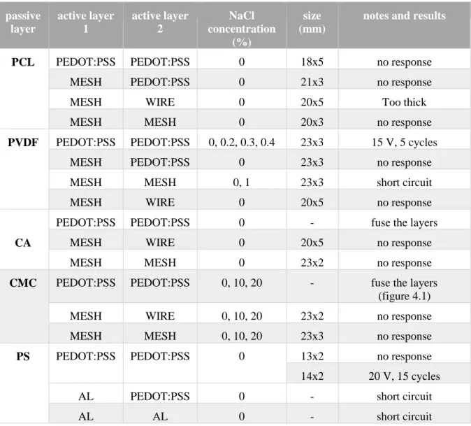
4.1 Preliminary study: selection of passive and active layers
Table 4.1: Study of several materials for passive and active layers with and without NaCl.passive layer active layer 1 active layer 2 NaCl concentration (%) size (mm)
notes and results
PCL PEDOT:PSS PEDOT:PSS 0 18x5 no response
MESH PEDOT:PSS 0 21x3 no response
MESH WIRE 0 20x5 Too thick
MESH MESH 0 20x3 no response
PVDF PEDOT:PSS PEDOT:PSS 0, 0.2, 0.3, 0.4 23x3 15 V, 5 cycles
MESH PEDOT:PSS 0 23x3 no response
MESH MESH 0, 1 23x3 short circuit
MESH WIRE 0 20x5 no response
CA
PEDOT:PSS PEDOT:PSS 0 - fuse the layers
MESH WIRE 0 20x5 no response
MESH MESH 0 23x2 no response
CMC PEDOT:PSS PEDOT:PSS 0, 10, 20 - fuse the layers (figure 4.1)
MESH WIRE 0, 10, 20 23x2 no response
MESH MESH 0, 10, 20 23x3 no response
PS PEDOT:PSS PEDOT:PSS 0 13x2 no response
14x2 20 V, 15 cycles
AL PEDOT:PSS 0 - short circuit
14
The results of the preliminary study show that only PEDOT:PSS as active layers and PVDF and PS as passive layers have potential to be explored as possible electroactive actuators. The PS results showed to be not reproducible. So, from this point further the study is focused on PE-DOT:PSS with PVDF.
However, this study shows the possibility to produce different polymer films with NaCl as ion additive, which could be explored for other possible applications such as batteries with a solid electrolyte. On the other hand, since CMC, CA solutions contain water and have a low melting point, when heating and depositing PEDOT:PSS, which the solution is also in water, they fuse like shown in figure 4.1. Since the focused electrode was PEDOT:PSS, those were rejected for further studies.
Figure 4.1: Fused PEDOT:PSS deposition in CMC film.
Another problem faced during this preliminary study was the peeling off of the PE-DOT:PSS from the PVDF film. This was solved by introducing in the process an extra coating step with polyelectrolytes, PSS and PDADAMAC, to create an interfacial layer and improving the adhesion.
Figure 4.2: Configuration of the device used for the tests.
The further study focused on the properties of coatings and polymeric membranes and its performance as electroactive device namely on how it influences the preparation parameters such as active layer thickness, conductivity, stability, and bendability.
4.2 Electrical properties: Influence of layer thickness
4.2.1 PEDOT:PSS active layer
The layer thickness of PEDOT:PSS was changed by varying the amount of PEDOT:PSS solution dropped on the substrate. Therefore, a correlation between them is of extreme importance for process’ reproducibility, considering a substrate with very good wettability. Figure 4.3 shows that film thickness and volume of dropped solution have a linear relation in the range of volume
used. Values below and above were tried however for lower values it was difficult to control the film thickness with drop cast method, while for values above the film was brittle and with the method used the active layer adherence was unsuitable for further tests.
Figure 4.3: PEDOT:PSS film thickness as a function of the PEDOT:PSS volume dropped in a 7.5 cmx2.5 cm substrate.
The conductivity of the PEDOT:PSS films of different thickness were measured after film deposition and three weeks later in order to observe any possible degradation of films. The ob-tained results shown in figure 4.4 reveal that films conductivity tend to increase with films thick-ness for values up to 7 m and then it is independent of thickthick-ness. This variation is maybe related to some heterogeneities of films since for the same thickness the conductivity should not vary. Moreover, the samples show a very smooth surface as can be seen in top view SEM image of figure 4.4. The data also show a degradation of films along storage time under environmental conditions. This can be attribute to the oxidation state of the film’s surface leading to annihilation of PEDOT:PSS’s protonation state.
Figure 4.4: PEDOT:PSS conductivity as a function of the film thickness measured after film deposition and three weeks later. Top view SEM image of a sample.
16
4.2.2 PVDF passive layer
The PVDF acts as passive layer and support of the electrodes and for that reason needs to fulfil two main characteristics. It should be insolating to avoid micro short-circuit between elec-trodes but also needs to be highly flexible. The flexibility is enhanced as the thickness decrease but then some micro porosities can enable the short-circuits. Thus, the influence of the film thick-ness on the conductivity of the PVDF films was evaluated. This can be observed in figure 4.5. It is observed a decrease in conductivity when the PVDF thickness increase, as expected for thicker film, meaning that the possible micro short-circuits start to be eliminated. In the same figure, can be observed the conductivity of samples left in atmospheric conditions during three weeks. The sample conductivity specially for thinner thickness corroborates somehow the possible micro-porous effect. Probably oxygen adsorption lead to a decrease in porosity and electrical charges have more difficulty to flow across de PVDF film.
Figure 4.5: PVDF conductivity variation with the film thickness right after film deposition and after three weeks.
4.3 Ionic conductivity of PVDF
To discard any possible contribution of ionic charges contained in the PVDF to the electro-mechanical stimuli, the ionic conductivity of PVDF and PVDF with NaCl (0.4%) was measured. Figure 4.6 shows the obtained results.
Figure 4.6: Variation of conductivity versus applied frequency for PVDF film and PVDF film with 0.4 % of NaCl
The ionic conductivity is calculated through a non-linear regression using the Jonscher equation (4), but PVDF shows non-ionic conductivity as the equation does not fit the results.
𝜎(𝜔) = 𝜎𝑑𝑐+ 𝐴𝜔𝑛 (4)
Were, 𝜎𝑑𝑐 , A and n are the dc conductivity, pre-exponential factor and fractional exponent, respectively. [14]
On graphic of figure 4.6 is possible to compare the conductivities between with and without NaCl. That results shows the decrease of conductivity along the frequency in both samples and that the sample with NaCl always shows higher conductivity than the sample without NaCl. Be-sides that the existence of plateau for lower frequency means that at lower frequency the conduc-tivity is mainly governed by dc conducconduc-tivity. [15] Therefore, the presence of NaCl enhance the interfacial contribution and dipolar relaxation modes. [16]
4.4 Mechanical tests
4.4.1 Tensile tests
The maximum stress and Young modulus was obtained for PVDF films with and without PEDOT:PSS coating. This allowed to understand how the mechanical properties of the films are influenced by the PEDOT:PSS layer since it contains some solvents that could contribute to brittle the samples. Figure 4.7 shows one of the stress-strain plots obtained from the mechanical testes and the others can be found in annex A. There is also found the calculations to obtain the values of table 4.2: Young Modulus, elongation at break and maximum stress, that are an average of 10 samples’ values.
18
Figure 4.7: Tensile test of one of the 10 samples of PVDF w/ NaCl.
From the stress-strain graphic from figure 4.7, it’s possible to obtain the maximum stress endured by the actuator through the maximum point on the Y axis. The elongation at break is visible on the X axis, when there is no more stress applied, meaning that the sample broke. For the Young modulus, as explained in chapter 3.4 it is measured by applying a linear regression in the linear zone, and the slope is the value of the Young modulus. Table 4.2 shows the mean results from a set of 10 samples for each tested condition.
Table 4.2: Materials and its characterization regarding Young modulus, elongation at break and maximum stress, using 10 samples for each material.
Material Average Thickness (μm) Dimensions (mm) Young modu-lus (MPa) Elongation at break (%) Maximum stress (MPa) PVDF 32 23x8 237±38.0 47.0±3.0 30.2±6.0 PVDF w/ PEDOT:PSS 43 21x8 228±81.0 44.0±3.0 49.8±10.2 PVDF w/ NaCl 33 23x8 236±56.0 57.0±3.0 27.1±5.9 PVDF w/ NaCl and PEDOT:PSS 46 21x8 220.0±64.0 53.0±10.0 32.3±11.4
According to literature, PVDF films has a tensile strength of 35-50 MPa and an elongation at break of 50%. [17] According the results of table 4.2 the maximum stress (tensile strength) is 30.2 MPa and have an elongation at break of 47.0%, the method used in literature is different than the one in this work, and the produced films have different thickness homogeneity, possibly hav-ing different outcomes that the one in literature.
Comparing the Young modulus we observe there is no change between the samples with and without PEDOT:PSS.
S
tre
ss (MP
a)
Regarding the comparison between with and without NaCl in the PVDF films, the Young modulus and maximum stress slightly decrease but are more plastic as the elongation at break is higher.
4.4.2 Mechanical bending
Mechanical bending is a test with the same experimental set up than the tensile test with the difference that in this test the sample has two contacts to measure the resistance when it is bending. Thus, with this test is aimed to understand how much bending angle and cycles the PEDOT:PSS layer support without degrading. Unlike the tensile test, the mechanical bending consists in pulling and pushing for several cycles, in this case, 130, the sample in a previous determinate length, in this case, 5 mm.
Until the end of the 130 cycles, the resistance of PEDOT:PSS layer show values between 94 and 113 Ohms, as shown in the graphic of figure 4.8.
Ω
Figure 4.8: Resistance variation along the cycles of the mechanical bending as well with the lower and higher limit of variation.
These results shown that the bending of sample will not cause any influence on resistance values while the maximum bending angle tested was 42°. The resistance mean value obtained is 99 Ω. This clearly indicates that the sample can endure several cycles without losing its electrical properties without addition of polyelectrolyte.
4.5 Electronic-stimuli
4.5.1 Influence on passive layer thickness
To understand the effect of PSS on the electrical behaviour of membranes I-V curves cy-cling was performed for samples soaked in PSS. The samples with variation only in the PVDF film thickness were dip coated in PSS to simulate the electroactive bending actuation test. For each sample, the I-V curves were taken applying forward and backward performing voltage cy-cles as shown in Figure 4.8. There are shown only the forward bias results as for the backward bias the values are almost symmetric.
20
Figure 4.9: IV curve of the sample with 8 μm thickness of PEDOT:PSS and a) 24 μm thickness of PVDF, b) 25 μm thickness of PVDF with NaCl, c) 36 μm thickness of PVDF and d) 39 μm of PVDF.
Figure 4.9 shows a decrease of conductivity with the increase of cycles, within the same sample. However, the conductivity has increased when PSS has added since without PSS the conductivity measured was 8x10⁻¹⁰ S/cm (figure 4.5) and with PSS was 5x10⁻⁸ S/cm (measured from the graph a from figure 4.9). That is, the decrease in the conductivity along the I-V cycling has maybe the same effect as the time already mentioned in 4.2.1. The thickness of PVDF layer has no remarkable influence in current variation neither the inclusion of NaCl ions on it.
The influence of thickness in the electrical conductivity was already shown in figure 4.5, but to understand if it influences the conductivity variation after electric stimuli, the values are plotted and compared in figure 4.10. The electrical conductivity after bending shows a slight de-crease although within the same order of magnitude and ticker PVDF films show lower variation in the conductivity. Again, what was stated for figure 4.5 is still valid for this variation, thicker PVDF films are probably less sensitive to micro short-circuits.
a) b)
d) c)
Figure 4.10: Variation of the conductivity with the PVDF thickness, before and after electrical stimuli.
4.5.2 Influence on active layer thickness
Similar study was performed for PEDOT:PSS films with thickness in the range of 5 μm to 8 μm and PVDF film of about 31 μm, that is, the conductivity was analysed after samples’ bend-ing, figure 4.11.
Figure 4.11: Variation of the planar conductivity with the PEDOT:PSS thickness before and after bending.
As showed before, the samples’ conductivity is enhanced as the PEDOT:PSS layer in-creases for thickness up to 7 m. Above that, there is a tendency to be independent of films thick-ness. After electrical stimulus, a decrease in conductivity of about one order of magnitude, is observed for lower thickness films. The thicker the active layer is, with the same amount of cycles, the lowest is the difference in conductivity before and after electroactive bending cycles. The difference can be due to the formation of cracks in the surface of the PEDOT:PSS film. It’s pos-sible to see this formation by using SEM to compare the two surfaces.
22
Knowing that thickness has a minor influence on the conductivity of PVDF films, after bending, and the PEDOT:PSS is also not greatly influenced by bending we have analysed the variation of transverse conductivity of PVDF with the number of cycles of electrical stimulation. A drop of PSS placed in contact with the PEDOT:PSS layer caused a decrease in the transverse conductivity of PVDF films as shown in figure 4.12. This is observed independently of the PE-DOT:PSS thickness and if PVDF films contains NaCl ions. In figure 4.12 is visible some spikes in cycle 4 and 7, that occurred due to renewing added PSS every 3 cycles.
Figure 4.12: Transversal conductivity variation along the cycles with PVDF thickness of 24 μm, varying PEDOT:PSS thickness and NaCl concentration.
The decrease of PVDF conductivity as the number of cycles increase reveal that PSS con-tribute to reduce some micro-short-circuit of membrane and therefore it is not a limiting factor for working performance of the devices as electroactive device. For it working properly is im-portant that the accumulated charge in the PEDOT:PSS layer is retained there and not transverse the PVDF membrane. As the PSS is added there is more active charges and it may explain the conductivity increase.
4.5.3 Electroactive bending
The bending displacement of the samples with different PVDF and PEDOT:PSS layer thickness can be observed in the images displayed in table 4.5 of device with and without elec-trical stimuli. The images are taken over a regular squared paper meaning that each square is 0.5 cm width. This way is possible to measure the displacement. These results as well as the voltage values to which was obtained the respective displacement are shown in table 4.5.
PEDOT (m)
PVDF (m)
Without eletrical stimuli With eletrical stimuli
8 24
8 W/ NaCl
25
5 24
Table 4.5: Bending displacement of the samples with different PVDF and PEDOT:PSS thicknesses. The square paper is a reference for the displacement measurement, a square has 5mm length.
24
7 24
6 24
8 39
Table 4.3: Materials, sizes and results for the electrical bending tests using PEDOT:PSS as active layer and sample size of 21x5 mm2. Passive layer Passive layer thickness (μm) Active layer thickness (μm) Voltage (V) Maximum displacement (mm) Time for displacement (s) PVDF 24 5 +78 1.79 45 24 6 +37 3.21 88 24 7 +15 5.42 91 24 8 ±15 10.81 232 36 8 +17 3.38 129 39 8 +20 3.42 154 PVDF w/ NaCl 25 8 ±15 6.00 261
The results of table 4.5 show that an increase of PEDOT:PSS thickness promotes a drop on the voltage needed to have displacement of the device, being achieved the minimum of 15V for a PEDOT:PSS layer of 8 μm. To this value corresponds also the highest displacement although it needs more time to happen, but shows as well positive and negative displacement when the inverse voltage is applied, that is reversibility.
For an active layer thickness of 5 and 6 μm, the voltage needed to have a displacement e very high, presenting values of electric field of 3.25 and 1.54 MV/m respectably, so it’s possible that this displacement can be due to the electrical polarization of PVDF. It’s necessary further study to confirm this statement.
On the contrary when PVDF layer thickness is enhanced the voltage increases again from 15 to 20 V and the displacement is only of about 3 mm.
The presence of NaCl has a minor influence on the results being obtained similar results in devices with and without ions in the PVDF layer.
These results led to the conclusion that the displacement observed when a polarization is imposed to the device is due to oxidation and reduction of the active layer (PEDOT:PSS) and not due to charge/ion movement promoted inside the PVDF layer. The application of a positive
po-26
The PVDF is known by its facility in performing this charge polarization. However, the PVDF films with aluminium foil on both sides were tried and no displacement was observed even for very high voltage applied. The process can be due to reduction and oxidation of the PEDOT:PSS, to verify a cyclic voltammetry study is needed.
In order to eliminate any possible structural and compositional change of PEDOT:PSS when in contact with PSS and after electrical stimuli, the Raman and FTIR spectra were acquired before and after electroactive bending. Figure 4.14, for Raman and figure 4.15 for FTIR.
Figure 4.13: Raman spectra of: PEDOT:PSS before the electroactive bending with polyelectrolyte (PSS) - black line; PEDOT:PSS before the electroactive bending - red line; PEDOT:PSS after electroactive bending - blue line.
As can be seen in the spectra from figure 4.14, all the peaks match in the three samples. The peaks related to the PEDOT polymer structure are the following: the strong peak centred at 1429 cm-1 due to the symmetric stretching mode of the aromatic C=C band; three important bands located at 1562, 1335 and 1257 cm-1 related to the antisymmetric Cα- Cα, Cβ- Cβ stretching deformations; Cα- Cα inter-ring stretching vibrations, respectively and the bands located at 985 and 576 cm-1 associated to the oxyethylene ring deformation. [18]
It was also found that the band for SO2 bending from PSS was located at 437 cm-1. [18] The comparison between the relative intensity of the two samples before electroactive bending shows that the sample with PSS has slightly more SO2 derived from the PSS added. Nevertheless, no structural modifications were observed.
Figure 4.14: FTIR spectrum of PEDOT:PSS before the electroactive bending with polyelectrolyte (PSS) - red line; PEDOT:PSS before the electroactive bending - black line; PEDOT:PSS after electroactive bending - blue line.
In figure 4.15 is visible four intense absorption peaks at 1005, 1125, 1076 and 1181 cm-1. The first one correspond to the -SO3 symmetric stretching vibrations and the others, correspond to the -SO3 asymmetric stretching vibrations. According literature, the peak between 1410 and 1495 cm-1 correspond to the C=C skeletal vibration of the aromatic rings. The peak at 1295 cm-1 correspond to the S=O vibration. At last, the peaks at 965 and 915 cm-1 can be assigned to the C-S bond of the thriophene ring in PEDOT. [19,20,25]
By making an analyses with XPS we can see if there is some surface changes along the different samples.
5 Conclusions and future perspectives
5.1 Conclusions
This work, as pioneer inside the group, and faced several difficulties that have been over-come. The adhesion of PEDOT:PSS to the polymer surface of support membranes was one of them. Indeed, by dip coating polymeric membranes in polyelectrolyte before coating with PE-DOT:PSS a significant improvement of adhesion and durability was achieved.
On the other hand, several materials were tested regarding its functionality under electronic stimuli, being concluded that PVDF was the one most promising, and therefore chosen for further studies.
During this work were studied several parameters that may influence the performance of final devices concerning electronic stimuli. As the PEDOT:PSS films were made by drop casting and subsequent drying at room temperature, the volume of drop and the respective film thickness was evaluated and a linear relation obtained, in the volume range studied. The influence of films thickness on the conductivity was also investigated, and although the conductivity should be in-dependent of films thickness the rudimentary of the process can originate non-uniform film spe-cially for lower thickness which justifies the variation on conductivity observed. A degradation of PEDOT films stored at atmospheric conditions was also observed.
The PVDF membranes were study regarding its ionic conductivity, with and without added NaCl and the influence of thickness on the electrical conductivity before and after contact with PSS. The ionic conductivity is higher in samples with NaCl although no remarkable difference is obtained in NaCl concentration used (the maximum that allowed to obtain an uniform film). Be-sides that, the existence of plateau for lower frequency means that at lower frequency dc conduc-tivity mainly governs the conducconduc-tivity. Therefore, the presence of NaCl atoms enhance the inter-facial contribution and dipolar relaxation modes. There transverse electrical conductivity de-creases along the cycles either in the whole sample and in the conductive layer, within the same sample, showing that when using the polyelectrolyte the durability is short, about 12 cycles. De-spite its low durability, the polyelectrolyte is important to improve conductivity, allowing the best performance of the samples.
By mechanical strain-stress tests the PVDF maximum stress is 30.2 MPa and the elongation at break is 47.1 % showing an accordance with the literature values of 35-60 MPa and 50% to maximum stress and elongation at break, respectably. [17] When coated with PEDOT:PSS or including NaCl in PVDF the samples are within the same range for maximum stress.
The mechanical bending to the device test shows that electrical resistance of PEDOT:PSS along 130 cycles is within the 94.7-113 Ω range and the bending up to an angle of 42 did not influenced greatly its properties.
Regarding the electroactive bending, the operation voltage increases when PVDF thickness increase and the conductive layer thickness decreases. The use of NaCl in PVDF passive layer, shows the same time of displacement and same displacement, but only when applied positive tension, so the displacement is enhanced in PVDF films without NaCl.
30
respectably, it can be conclude that, in the used range, smaller the PVDF thickness and thicker the PEDOT:PSS layer, the better.
5.2 Future perspectives
For all the applications presented in chapter 1, one of the most important characteristic is the actuator durability. Since the methods presented offers a low durability, it is important to improve the characteristic. For that the adherence between the active layer and the passive layer is crucial, so this should be optimized.
Besides the method used for the adhesion of the three layers, others should be studied, like a metal thin layer as interfacial layer [11], changing the active layer deposition atmospheric con-ditions to control its oxidation, for example, deposit the PEDOT:PSS layer in an inert gas atmos-phere. [9]
The PVDF film used has no porosity, and some articles reveal the difference in the actuator when the porosity change, so a study in the actuation functionality with the porosity variation should be made. Also should be studied the piezoelectric effect of the PVDF and DRX to see if there is the presence of the PVDF p-phase.
With the use of alternative methods, is important so know how others passive and active layer’s thickness could influence the actuation time and displacement. And, also, see if the con-clusions regarding the thickness, maintain with others thickness, and the same using different methods.
Since the actuator in study bends when a voltage is applied and with a polyelectrolyte so-lution, is also important to study its piezoelectric effect, and its bending movement and time when in solutions with different pH.
To see if the electroactive bending mechanism is due to the oxidation/reduction of the PEDOT:PSS film, it’s important to make cyclic voltammetry of the samples. Also, it’s necessary to see how the deflection of the beam changes with the cycles and investigate the thermal effect on PEDOT:PSS films.
6 Bibliography
[1] G. G. Malliaras, “Organic bioelectronics: A new era for organic electronics,” Biochim.
Biophys. Acta - Gen. Subj., vol. 1830, no. 9, pp. 4286–4287, 2013.
[2] T. F. Otero, J. G. Martinez, and J. Arias-Pardilla, “Biomimetic electrochemistry from conducting polymers. A review,” Electrochim. Acta, vol. 84, pp. 112–128, 2012.
[3] K. Kwon and T. Nga, “Improving electroactive polymer actuator by tuning ionic liquid concentration,” Org. Electron., vol. 15, no. 1, pp. 294–298, 2014.
[4] R. M. Owens and G. G. Malliaras, “Organic Electronics at the Interface with Biology,”
MRS Bull., vol. 35, no. 6, pp. 449–456, 2010.
[5] J. D. W. M. Y. Bar-Cohen, K. J. Kim, H. R. Choi, “Electroactive polymer materials,”
Smart Mater. Struct., vol. 16, 2007.
[6] F. Carpi, R. Kornbluh, P. Sommer-Larsen, and G. Alici, “Electroactive polymer actuators as artificial muscles: are they ready for bioinspired applications?,” Bioinspir. Biomim., vol. 6, no. 4, p. 45006, 2011.
[7] S. T. McGovern et al., “Evaluation of thrust force generated for a robotic fish propelled with polypyrrole actuators,” Polym. Int., vol. 59, no. 3, pp. 357–364, 2010.
[8] M. Itik, “Sensors and Actuators A : Physical Repetitive control of a trilayer conjugated polymer actuator,” Sensors Actuators A. Phys., vol. 194, pp. 149–159, 2013.
[9] K. Ikushima, S. John, A. Ono, and S. Nagamitsu, “PEDOT/PSS bending actuators for autofocus micro lens applications,” Synth. Met., vol. 160, no. 17–18, pp. 1877–1883, 2010. [10] R. Temmer, A. Maziz, and A. Aabloo, “In search of better electroactive polymer actuator materials : PPy versus PEDOT versus PEDOT – PPy composites,” Smart Mater. Struct., vol. 22, no. 10, 2013.
[11] G. Alici and D. Gunderson, “A bio-inspired robotic locomotion system based on conducting polymer actuators,” IEEE/ASME Int. Conf. Adv. Intell. Mechatronics, AIM, pp. 998–1004, 2009.
[12] G. M. Spinks, G. G. Wallace, J. Ding, D. Zhou, B. Xi, and J. Gillespie, “Ionic Liquids and Polypyrrole Helix Tubes: Bringing the Electronic Braille Screen Closer to Reality,” Smart
Mater. Struct., vol. 5051, pp. 372–380, 2003.
[13] G. Spinks and G. Wallace, “Electroactive polymer actuator devices (EAPAD),” Smart
Mater. Struct., vol. 5051, pp. 21–28, 2003.
[14] N. Shukla, A. K. Thakur, A. Shukla, and D. T. Marx, “Ion conduction mechanism in solid polymer electrolyte: An applicability of almond-west formalism,” Int. J. Electrochem.
Sci., vol. 9, no. 12, pp. 7644–7659, 2014.
[15] S. Roy, P. Thakur, N. A. Hoque, B. Bagchi, and S. Das, “Enhanced electroactive [small beta]-phase nucleation and dielectric properties of PVdF-HFP thin films influenced by montmorillonite and Ni(OH)2 nanoparticle modified montmorillonite,” RSC Adv., vol. 6, no. 26, pp. 21881–21894, 2016.
32
electroactive [small beta] phase nucleation and dielectric properties of WO3[middle dot]H2O nanoparticle loaded poly(vinylidene fluoride) thin films,” RSC Adv., vol. 5, no. 77, pp. 62819–62827, 2015.
[17] B. Mohammadi, A. A. Yousefi, and S. M. Bellah, “Effect of tensile strain rate and elongation on crystalline structure and piezoelectric properties of PVDF thin films,”
Polym. Test., vol. 26, no. 1, pp. 42–50, 2007.
[18] A. A. Farah, S. A. Rutledge, A. Schaarschmidt, R. Lai, J. P. Freedman, and A. S. Helmy, “Conductivity enhancement of poly(3,4-ethylenedioxythiophene)-poly(styrenesulfonate) films post-spincasting,” J. Appl. Phys., vol. 112, no. 11, p. 113709, 2012.
[19] Z. Zhu, H. Song, J. Xu, C. Liu, Q. Jiang, and H. Shi, “Significant conductivity enhancement of PEDOT:PSS films treated with lithium salt solutions,” J. Mater. Sci.
Mater. Electron., vol. 26, no. 1, pp. 429–434, 2014.
[20] W. Cho, S. Im, S. Kim, S. Kim, and J. Kim, “Synthesis and Characterization of PEDOT:P(SS-co-VTMS) with Hydrophobic Properties and Excellent Thermal Stability,”
Polymers (Basel)., vol. 8, no. 5, p. 189, 2016.
[21] Y. Liu et al., “Enhanced Dispersion of TiO2 Nanoparticles in a TiO2/PEDOT:PSS Hybrid Nanocomposite via Plasma-Liquid Interactions,” Sci. Rep., vol. 5, no. October, p. 15765, 2015.
[22] S. W. John, “Modelling and control of conducting polymer actuators,” PhD Thesys Uni.
Wollongong, vol. 2066, 2008.
[23] R. Balint, N. J. Cassidy, and S. H. Cartmell, “Acta Biomaterialia Conductive polymers : Towards a smart biomaterial for tissue engineering,” Acta Biomater., vol. 10, no. 6, pp. 2341–2353, 2014.
[24] L. Persano, A. Camposeo, and D. Pisignano, “Progress in Polymer Science Active polymer nanofibers for photonics , electronics , energy generation and micromechanics,”
7 Annex
Annex A – Tensile test graphics
Strain (mm/mm) Strain (mm/mm)
Strain (mm/mm) Strain (mm/mm)
Strain (mm/mm) Strain (mm/mm)
34
Strain (mm/mm) Strain (mm/mm)
Strain (mm/mm) Strain (mm/mm)
Strain (mm/mm) Strain (mm/mm)
Strain (mm/mm) Strain (mm/mm)
36 Strain (mm/mm) Strain (mm/mm) Strain (mm/mm) Strain (mm/mm) Strain (mm/mm) Strain (mm/mm) Strain (mm/mm) Strain (mm/mm)

![Figure 2.5: The INTACT TM refreshable Braille screen under development by Quantum Technology, Aus- Aus-tralia.[12]](https://thumb-eu.123doks.com/thumbv2/123dok_br/19231688.967666/26.892.241.696.223.438/figure-intact-refreshable-braille-screen-development-quantum-technology.webp)
![Table 2.1: Some EAP companies and a list of several products under development in 2011 [6]](https://thumb-eu.123doks.com/thumbv2/123dok_br/19231688.967666/27.892.137.767.160.588/table-eap-companies-list-products-development.webp)