1
This article was published in Fuel, 159, 854-863, 2015 1
http://dx.doi.org/10.1016/j.fuel.2015.07.035 2
3
Enhancing the low temperature water-gas shift reaction through a
4
hybrid sorption-enhanced membrane reactor for high-purity hydrogen
5
production
6 7
M. A. Soria1, S. Tosti2, A. Mendes1, Luis M. Madeira1*
8
9
1 LEPABE – Chemical Engineering Department, Faculty of Engineering - University of
10
Porto, Rua Dr. Roberto Frias, s/n, 4200-465 Porto, Portugal. 11
2ENEA – Unità Tecnica Fusione, C.R. ENEA Frascati, Via E. Fermi 45, Frascati
12
(RM) I-00044, Italy. 13
14
15
* Corresponding author. Tel.: +351-22-5081519; Fax: +351-22-5081449; E-mail:
16
2
Abstract
19 20
The low temperature water-gas-shift reaction (LT-WGS) has been assessed by means of 21
a hybrid sorption-enhanced membrane reactor (HSEMR) that combines both CO2 and H2
22
removal from the reaction zone. The performance of this reactor has been compared with 23
that obtained by i) a traditional and ii) a sorption-enhanced (only CO2 is removed) reactor
24
operating in the same operational conditions. Cu/ZnO-Al2O3 and K2CO3-promoted
25
hydrotalcite materials have been used as a catalyst and CO2 sorbent, respectively. A
self-26
supported Pd-Ag membrane tube has been used in order to selectively separate the H2.
27
The CO2 sorption capacity, in the presence and absence of water vapour, of the
potassium-28
promoted hydrotalcite has been determined by means of breakthrough experiments. The 29
presence of water vapour enhanced the sorption capacity of the hydrotalcite in the 30
experimental conditions used. Concerning the performance of the HSERM, results clearly 31
show that when both CO2 and H2 are removed from the reaction zone, the hydrogen
32
production through the reversible LT-WGS reaction is enhanced compared to either a 33
traditional or a sorption-enhanced reactor, allowing overcoming equilibrium limitations 34
and obtain a pure H2 stream.
35
36
Keyword: Water-gas shift, hydrotalcite, CO2 sorption, membrane reactor, sorption
37
enhanced, hydrogen. 38
3
1. Introduction
39
Hydrogen is an important raw material widely used in the chemical industry (i.e. oil 40
refining and production of bulk chemical such as methanol and ammonia) and as clean 41
energy vector for fuel cells and internal combustion engines [1,2]. Global demand of 42
hydrogen is even growing. Currently, most of the hydrogen produced in the world 43
involves methods such as methane steam reforming (MSR), coal gasification, water 44
electrolysis, biomass gasification and thermochemical process, being MSR the most 45
widely used among them [3,4]. In MSR, the outlet stream contains a large amount of CO 46
as by-product along with hydrogen (H2/CO ratio >3); the CO content varies between 8 %
47
and 10 % depending of the feedstock composition and conditions used [5]. In order to 48
purify the hydrogen in the MSR reactor effluent and/or tune the CO/H2 ratio, the syngas
49
stream can be treated in a water-gas shift (WGS, eq. 1) reactor. 50
CO + H2O = H2 + CO2 ΔH0298 = -41 kJ mol-1 (1)
51
This chemical equilibrium-limited reaction is a mildly exothermic and hence is 52
thermodynamically favoured at low temperatures, although kinetically favoured at high 53
temperatures. For this reason, to obtain high CO conversion, the WGS reaction is 54
industrially carried out in two successive steps at different temperatures, namely: (i) a 55
high-temperature water gas-shift (HT-WGS) reactor operating between 350 ºC and 56
550 ºC and (ii) a low-temperature water-gas shift (LT-WGS) reactor at 200-300 ºC. The 57
first shift reactor works with iron-chrome oxide catalysts and has an output stream 58
containing 1.5-4.0% CO, while the second reactor operates with copper-zinc oxide 59
catalysts where the CO outlet composition is reduced to about 0.5-1.0% [5,6]. 60
The gas produced from the WGS reaction contains other components (mainly CO, CO2,
61
H2O and CH4) apart from H2. Remaining steam can be relatively easily removed by water
62
condensation, while COx and CH4 are often removed through processes such as pressure
4
swing adsorption (PSA) to produce high purity hydrogen [7]. This PSA process generally 64
operates at near ambient temperature (20-40 ºC) using CO2 microporous physisorbents
65
such as activated carbons and zeolites [8]. With this cyclic PSA, hydrogen with 99.99 % 66
purity is obtained but the H2 recovery is about 75-90 % only since part of the H2 recovered
67
is used to regenerate the adsorbent [9]. This means that a considerable amount of H2
68
produced in this process is lost. 69
One alternative to the PSA process to separate H2 is by removing it from the reaction zone
70
by means of one H2 perm-selective membrane. In this way, not only is possible to obtain
71
ultra-pure H2, suitable for fuel cells [5], but also the equilibrium limitation can be
72
circumvented by shifting the WGS reaction to the products side in a single unit. Hydrogen 73
perm-selective membranes have been developed using mainly palladium and its alloys 74
[10-12]. These Pd-based membranes show a very high H2 selectivity and allow reaching
75
CO conversions close to 100 % in membrane reactors (MR) for the LT-WGS reaction 76
[11,13]. 77
On the other hand, the capture and simultaneous separation of CO2 from the reaction zone
78
has also been proposed [9,14]. This process, so called sorption enhanced water gas shift, 79
allows to overcome the equilibrium limitation maximizing the H2 production from the
80
syngas as well. Different oxide materials as CO2 sorbent, such as calcium oxide, lithium
81
zirconates and lithium silicates, have been extensively studied [15,16]. Nevertheless, 82
these sorbents have a poor CO2 capacity at low temperatures and for their regeneration
83
temperatures above 700 ºC are required. Furthermore, these materials exhibit a 84
progressive loss of their CO2 sorption capacity under consecutive cycles of
adsorption-85
desorption. However, hydrotalcite-like (HTs) materials could be an attractive option for 86
CO2 sorption because of their high sorption capacity at lower temperatures (200-400 ºC),
87
which are compatible with WGS reaction [17-19]. Moreover, HTs present a lower 88
5
requirement of energy input for their regeneration, as well as acceptable working capacity 89
after multiple cycles and suitable kinetics of carbon dioxide sorption and desorption [18-90
20]. 91
A new field of research herein addressed deals with the study of innovative 92
multifunctional reactors by combining the MR concept with the sorption-enhanced one. 93
This has a large number of advantages: (i) the process may be performed in a single unit, 94
which simplifies the overall hydrogen production, (ii) compared to a MR, it allows 95
decreasing the required Pd membrane area, often limitative due to its price, (iii) the 96
reaction may be conducted with a lower H2O/CO ratio, thereby reducing steam usage and
97
operational costs, (iv) fuel-cell grade (i.e. high-purity) hydrogen can be directly produced, 98
and (v) the process captures CO2, so that is environmentally friendly and allows
99
eliminating the need for a dedicated CO2 capture unit.
100
The aim of this work is to study this new concept in a multifunctional hybrid sorption- 101
enhanced membrane reactor. For this purpose, a self-supported Pd-Ag membrane and a 102
commercial hydrotalcite mixed with a LT-WGS Cu-based catalyst have been used. In 103
practice, and because the sorbent regeneration is necessary when the CO2 starts breaking
104
through the column, and to ensure a continuous production, the use of two parallel 105
reactors is envisaged; while one of them is producing H2, the other one is the regeneration
106
stage. Thus, each of these reactors requires repetition of reaction-regeneration cycles 107
along time. 108
2. Experimental
109
For the experiments, a commercial K2CO3 promoted hydrotalcite supplied by Sasol was
110
used. This material, containing 17 wt. % of K2CO3 and Mg/Al mass ratio of 0.5, was
111
labelled as MG30-K. 112
6
2.1. Thermogravimetric and differential scanning calorimetry (TG-DSC) analysis. 114
TG-DSC analysis of fresh MG30-K sample was performed in a thermobalance 115
NETZSCH SSA 449F3 Jupiter. Approximately 20 mg of sample was placed in a platinum 116
basket and heated in N2 flow (50 mlN/min) from room temperature up to 900 °C at a
117
heating rate of 10 °C/min. All data analyses were performed using NETZSCH Proteus 118
Thermal Analysis software. 119
120
2.2. Breakthrough measurements. 121
Carbon dioxide breakthrough runs were carried out in a stainless steel tube (120 mm long 122
and with 10 mm o.d.), which was placed into an electric oven (Memmert, Type UNE200), 123
controlled by a programmable temperature controller. 2.8 grams of hydrotalcite framed 124
in both ends by mean of two discs of stainless steel mesh (10-15 μm) were used. In order 125
to minimize pressure drop along the bed, the particle size of the hydrotalcite used in the 126
experiments was between 355-550 µm. Before the experiments, the MG30-Ksample was 127
heated under 100 mlN/min of N2 at 300 ºC during 2h (to remove loosely interlayer water,
128
as described below). 129
Experiments were carried out in the presence as well as in absence of water vapour. Thus, 130
different feeds were used: (i) for dry conditions 10 or 15 vol. % of CO2 and balance N2
131
and (ii) for wet conditions 15 vol. % of CO2, 5, 15 or 25 vol. % of H2O and balance N2.
132
Both CO2 and N2 were fed to the process with mass flow controllers (model F201 from
133
Bronkhorst High-Tec) whereas the water vapor was produced in a Controlled Evaporation 134
and Mixing (CEM) system (Bronkhorst High-Tec). In both cases, the total flow rate (dry 135
basis) was kept at 100 mlN/min. The experiments were carried out at 1, 2 and 3 bar of
136
total pressure. 137
7
Evolution of the outlet CO2 dry composition was monitored by an online infrared based
138
CO2 analyser (model 4210 from Servomex); the H2O present in the outlet stream was
139
condensed through a Peltier based cold-trap located at the exit of the sorber and prior to 140
the analyser. With the purpose of determining the dead volume in the system, for 141
correcting the breakthrough time and determining the total CO2 uptake, blank experiments
142
were performed in the same operational conditions but using only glass beads of the same 143
size to fill the column. 144
The regeneration capacity of the sorbents was assessed in multiples sorption-desorption 145
cycles. The procedure was as follows: (i) sorption step, performed until the feed 146
concentration (dry basis) was reached at the column outlet and (ii) desorption step, carried 147
out under N2 flow (100 mlN/min) until almost no CO2 was detected in the outlet stream
148
(~30 min). The CO2 sorption capacity of the hydrotalcite was calculated integrating the
149
area above the breakthrough curve and from the molar flow rate and mass of sorbent. The 150
breakthrough time was defined as the instant at which 5 % of the inlet concentration was 151
reached. 152
2.3 Sorption enhanced water-gas shift reactor (SER) experiments. 153
Experiments were carried out in a fixed-bed reactor. This reactor consists in a stainless 154
steel tube with a length of 120 mm and 10 mm o.d., loaded with a commercial Cu/ZnO-155
Al2O3 catalyst (supplied by REB Research & Consulting; Ø = 250 -550 μm), mixed with
156
MG30-K sorbent (Ø = 355 -550 μm) in a catalyst/sorbent weight ratio of 1/12 and framed 157
in both ends by two discs of stainless steel mesh (10-15 μm). 158
The Cu-based catalyst was firstly reduced at 300 ºC for 2 h under a mixture of 15 vol. % 159
H2 diluted in N2 (45 mlN/min of total flow rate); subsequently, the system was flushed
160
with nitrogen (ca. 50 mlN/min) during 30 min to remove H2.
8
The sorption enhanced tests were performed at 3 bar, at 250 and 300 ºC, with a feed of 162
CO (10 vol. %), H2O (15 vol. %) and N2 (75 vol. %) and a total flow rate of 100 mlN/min.
163
The contact time, Wcat/QCO, used was 3.7 x 10⁻⁴ gcat h mlN-1.
164
The units that compose the experimental set-up have been described in detail elsewhere 165
[21]. The evolution of the outlet stream composition (i.e. mole fraction of CO and CO2)
166
was monitored online by means of an infrared CO and CO2 analyzer (Servomex, model
167
4210, accuracy of the measurement ±1% FS). Gas chromatography was used to detect 168
other products, apart from CO and CO2.
169
Table 1 summarizes the different operating conditions used for the tests described in this 170
section, aiming comparing the traditional packed-bed reactor with the sorption-enhanced 171
reactor. 172
2.4 Hybrid sorption-enhanced membrane reactor (HSEMR) experimental system. 173
A self-supported Pd-Ag membrane tube was used in order to selectively separate the 174
formed H2 from the reaction zone. Such a tube was produced by means of cold-rolling
175
and diffusion welding according to a previously described technique [11,22]. An annealed 176
commercial metal foil with 50 µm thickness and 25 wt. % of Ag (from Johnson Matthey) 177
has been used for this purpose. The total length and diameter of the permeator tube were 178
120 and 10 mm respectively, being that the Pd-Ag membrane (50 mm of length) was 179
placed in the middle of the tube. 180
HSEMR experiments were carried out in the same setup and experimental conditions 181
described in section 2.3, except that in this case a catalyst/sorbent mass ratio of 1/5 was 182
used. The amount of sorbent used for HSEMR and SER tests was smaller than for the 183
tests described in section 2.3 because the length of the Pd-Ag membrane is lower than 184
that of the reactor tube used for SER. The operational conditions used in the tests 185
described in this section are compiled in Table 2. Particularly, higher pressures were 186
9
employed in the retentate side, but to respect the limited resistance integrity of the used 187
self-supported membrane, total pressure difference across the membrane was not higher 188
than 2. However, because a high sweep gas (nitrogen) flow rate was employed, partial 189
pressure of hydrogen in the permeate side is negligible, allowing this way to increase 190
permeation driving force. 191
Fig. 1 displays the HSEMR configuration, in which the sorbent along with the catalyst 192
are placed inside the Pd-Ag membrane tube. The feed is introduced by the smaller 193
diameter tube and then goes through the sorbent-catalyst bed; the H2 that permeates from
194
the reaction zone is swept away by the N2 through the annular region formed by the
195
concentric Pd-Ag membrane and shell tubes. 196
Prior to the test, the membrane was activated until the permeate H2 flow rate was constant.
197
Such activation was performed feeding 60 mlN/min of pure H2 at 3.5 bar of pressure and
198
using 300 mlN/min of N2 as sweep gas in the permeate side (P = 1 bar).
199
For both SER and HSEMR tests, carbon monoxide conversion was defined as follows: 200 𝑋𝐶𝑂 (%) =𝐹𝐶𝑂 𝑖𝑛−𝐹 𝐶𝑂𝑜𝑢𝑡 𝐹𝐶𝑂 𝑖𝑛 x 100 (2) 201 where 𝐹𝐶𝑂𝑖𝑛 and 𝐹
𝐶𝑂𝑜𝑢𝑡 are respectively the molar rate flows of CO at the inlet and outlet of
202
the reactor. 203
3. Results and discussion
204
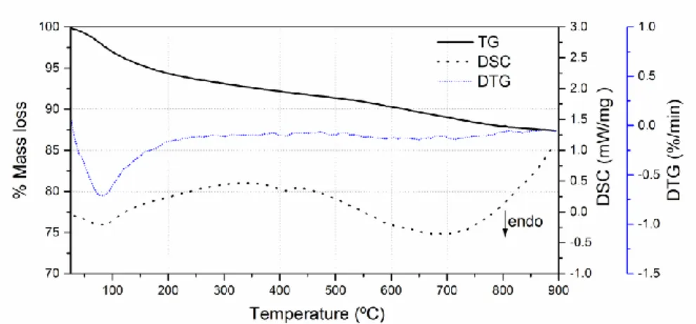
3.1 TG/DTG/DSC analysis 205
Fig. 2 shows the TG/DSC profile for the as supplied MG30-K hydrotalcite. This sample 206
exhibits a two-step mass loss: (i) around 7 % of the initial mass is lost between room 207
temperature and 300 ºC and (ii) further 6 % from 300 ºC to 900 ºC. The mass loss rate is 208
higher for low temperatures (<200 ºC) and then slightly decreases as the temperature 209
increases. 210
10
The DSC profile exhibits three endothermic peaks; at ~90 ºC related to physical 211
desorption of loosely interlayer water, at ~400 ºC attributed to dehydroxylation and 212
carbon dioxide removal and at ~700 ºC which was assigned to K2CO3 decomposition
[23-213
27]. 214
According to the information provided by the supplier, the MG30-K hydrotalcite was 215
previously calcined at 250 ºC for 1 h and then heated at 450 ºC for 24 h. This suggests 216
that the decarbonation that is typically observed in K2CO3 promoted hydrotalcites [28]
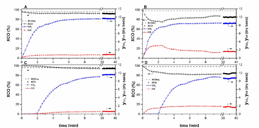
217
already occurred during the previous thermal treatment made by the supplier. Indeed, the 218
mass loss at around 400 ºC was small, indicating that the amount of carbonates present in 219
the as supplied MG30-K is very low. This is confirmed by the short peak observed in the 220
DSC profile at said temperature. Hence, the mass loss observed in our case is probably 221
due to the elimination of carbonate that remains in the sample or from CO2 present in the
222
atmosphere, which was sorbed and incorporated into the structure during storage. 223
On the other hand, in order to perform breakthrough and other experiments, the MG30-224
K was previously heated for 2 h at 300 ºC (as described in section 2.2). In such thermal 225
condition, the loosely interlayer water would be removed according to the results 226
observed in TG. As the carbonates are almost not present in the sample, it was not 227
necessary a thermal pre-treatment at higher temperatures inasmuch as the sample already 228
possess a molecular structure having high affinity for CO2.
229
3.2 CO2 breakthrough measurements
230
The results obtained during CO2 (15 vol. %) sorption for the MG30-K at 300 ºC and
231
different total pressures are shown in Fig. 3. The plots display the evolution of the 232
normalized CO2 molar fraction [y(t)/y0] in the outgoing gas as a function of time. As
233
observed in this figure, for all the pressure assessed, the outlet CO2 molar fraction (yCO2)
234
reaches the fed value (y0CO2) after about 960 s. However, the higher is the CO
2 partial
11
pressure, the higher are both the breakthrough time and the total CO2 capacity (inset of
236
Fig. 3). 237
On the other hand, the breakthrough time increases when the CO2 feed composition
238
decreases (15 vs 10 vol. %) at constant pressure as can be seen in Fig. 4. But in this case 239
the total CO2 capacity diminishes from 0.41 to 0.36 mol/kg. Such increase of the
240
breakthrough time observed is due to the CO2 flow rate, which decreases, and therefore
241
longer is the time required by the sorbent to begin being saturated with the sorbate. In 242
fact, because the CO2 isotherm is of the favorable type, the concentration front moves at
243
a higher velocity for increasing CO2 concentrations [29].
244
3.2.1 Study of sorption-desorption cycles 245
The regeneration and stability of the sorbent is a very important aspect for its application 246
in industrial processes that require successive cycles of sorption-desorption. Fig. 5 shows 247
the variation of the relative CO2 concentration as a function of the sorption-desorption
248
time for the MG30-K hydrotalcite. In the same figure it is represented the measured CO2
249
sorption capacity (on the right y-axis) and the cycle number (on the top x-axis). The first 250
cycle represents the CO2 sorption by the fresh sample while cycles from second to sixth
251
correspond to CO2 sorption after desorption under pure N2 flow. It is observed that the
252
CO2 sorption capacity undergoes a sharp decrease from the first to the second cycle, from
253
0.41 to 0.25 mol/kg, which corresponds to a loss of 40 %. However, from the third cycle 254
on, the CO2 sorption capacity (0.22 mol/kg) remains almost unchanged with the number
255
of cycles; in this case the CO2 sorption capacity is 46 % lower than the initial value
256
measured in the first cycle. This suggests that, in dry conditions, only 54 % of the initial 257
CO2 sorption capacity can be used, while the rest (0.19 mol/kg) remains irreversibly
258
sorbed on the hydrotalcite. A similar behavior has been also reported previously [19,26]. 259
12
It is well known that the presence of water vapour improves the CO2 sorption capacity of
261
hydrotalcites [26,30]. This is a very important aspect for the sorption-enhanced WGS 262
reaction since the feed contains water vapour, which could influence the hydrotalcite 263
sorption capacity of CO2 produced during the reaction. Therefore, it was assessed the
264
effect of different water vapour compositions on the CO2 sorption capacity of MG30-K
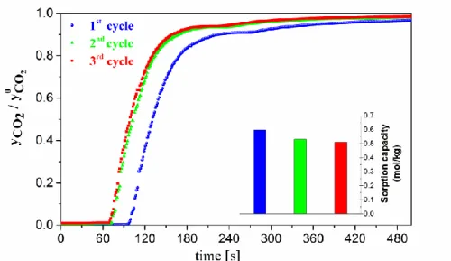
265
hydrotalcite. Fig. 6 exhibits the CO2 sorption breakthrough curves in consecutive
266
sorption–desorption cycles over the MG30-K hydrotalcite under wet conditions (15 vol. 267
% of water vapour); for practical reasons only until the third cycle is shown. The second 268
and third cycles correspond to CO2 sorption after desorption under N2 flow at 300 ºC and
269
1 bar. Table 3 presents the sorption capacity as a function of the cycle number, for these 270
and other experiments with different H2O contents in the feed. It is observed that the
271
higher is the quantity of water vapour fed, the higher is CO2 sorption capacity. However,
272
for the same water composition, it decreases with the number of cycles (but only up to 273
the third), being this effect more significant between the first and second cycle. Hence, a 274
similar trend regarding to sorption-desorption cycles, in dry conditions, was observed. 275
However, in wet conditions, a lower loss of the sorption capacity was observed in the 276
second and third cycle, remaining constant afterwards (data not shown). Comparing the 277
behaviour of the MG30-K in dry and wet conditions (Table 3), it is clear that the presence 278
of water vapour enhances considerably the sorption capacity. This issue and the fact that 279
the sorbent shows a higher reversibility during sorption-desorption cycles is essential for 280
its practical application in the sorption-enhanced WGS process. It should be noted, 281
however, that when an excess of water vapour (25 vol. %) was fed, the sorption capacity 282
was not linearly improved as it was observed for 5 and 15 vol. % (Table 3). It was reported 283
that an excess of water, sorbed on the surface, does not improve the sorption capacity, 284
which was associated with an increase of the diffusion resistance due to shrinkage of the 285
13
pore mouths [31]. Moreover, for 25 vol.% of water in the feed, the hydrotalcite sorption 286
capacity in the consecutive cycles did not remain so high as for 5 and 15 vol.% (Table 3). 287
The positive effect on the CO2 sorption capacity in presence of water vapour is likely due
288
to structural changes of the hydrotalcite-like sorbent. It was suggested that water 289
molecules react with Mg and Al oxide producing hydroxides that react with CO2 forming
290
its respective bicarbonates [32]. 291
3.3 Sorption enhanced water-gas shift 292
The CO2 and CO composition (on a dry basis), as well as the CO conversion obtained
293
during WGS reaction in both traditional fixed-bed and sorption-enhanced reactor, at 294
250 ºC and 300 ºC and 3 bar, are represented in Fig. 7(A-D). As can be seen in figure 7A 295
(300 ºC), the CO2 and CO are detected simultaneously in the reactor outlet, meaning that
296
both gases start breaking through the bed at the same time. However, the CO composition 297
attains a steady value (~1 %) at about 2 minutes while in the case of CO2 it takes around
298
6 minutes to reach a stable value of ~9.5%. Regarding to the CO conversion, from ca. 2 299
minutes of reaction it has a constant value (~92 %), which is close to the thermodynamic 300
equilibrium value (~96 %, calculated based on feed conditions). 301
For the test carried out at 250 ºC and 3 bar (Fig. 7B), the CO and the CO2 also break
302
through the bed at the same time. The CO composition reaches a maximum in the first 303
two minutes, then steadily decreases until it stabilizes after 30 minutes of reaction while 304
the CO2 composition strongly increases in the 5 initial minutes and then tends to stabilize
305
reaching a plateau. With regard to the CO conversion, it decreases in the first two minutes, 306
and then stabilizes according to the variation of CO composition. The CO and CO2
307
composition reach constant values of 1.8 and 8.6 vol. %, respectively. Such a steady-state 308
composition represents a CO conversion close to 83 % (under such conditions 309
equilibrium conversion is 98 %). While thermodynamic equilibrium conversion is higher 310
14
in Fig. 7B (250 ºC) than in Fig. 7A (300 ºC), which is a consequence of the exothermic 311
nature of the WGS reaction, the opposite occurs for the fixed bed reactor performance, 312
due to kinetic reasons. 313
In order to verify if the MG30-K hydrotalcite is catalytically active towards the WGS 314
reaction in the herein used working conditions, a test employing only the sorbent has been 315
performed. For the test carried out over the MG30-K hydrotalcite at 300 ºC and 3 bar, the 316
CO composition became stable after 20 minutes (data not shown) reaching a value of 11.2 317
vol. % on a dry basis, while the CO2, which is absent in the feed, presents a breakthrough
318
time close to 5 minutes and a composition of 0.4 vol. % after 30 minutes of reaction. This 319
evidences that the WGS reaction takes place at 300 ºC without the Cu/ZnO-Al2O3
320
catalyst, but the values of CO conversion obtained with the hydrotalcite are very low 321
(about 4.5%). Contrarily to what was observed at 300 ºC, at 250 ºC the MG30-K 322
hydrotalcite does not catalyses the WGS reaction (data not shown). Maroño et. al. [33] 323
have also observed that the hydrotalcite is catalytically active for the WGS reaction, but 324
for a range of temperatures between 300 ºC and 400 ºC and 14 bar of pressure. In that 325
case a higher CO conversion was observed; however, the sorbent strongly loses its 326
catalytic activity when submitted to reaction-regeneration cycles. In our case, since the 327
hydrotalcite shows a low activity in the conditions assessed, its behavior under reaction-328
regeneration cycles was not studied into further detail. 329
Fig. 7C illustrates the effect of carrying out the CO2 sorption and the WGS reaction
330
simultaneously, in this case using MG30-K and Cu/ZnO-Al2O3 as sorbent and catalyst,
331
respectively, in a mixed bed. The sorption-enhanced concept is clearly shown by 332
comparing Figures 7A and 7C. In fact, it is possible to observe that when a mixture of 333
sorbent and catalyst is used, the CO2 breakthrough time is delayed about 2 minutes (Fig.
334
7C) as compared to the time taken for the test carried out in the same operational 335
15
conditions but only with the catalyst (Fig.7A). This suggests that, in the pre-breakthrough 336
zone, while the CO2 is selectively removed from the gas phase by means of the sorbent,
337
the reaction is being shifted to produce more H2. This is corroborated by the fact that in
338
the pre-breakthrough zone no CO was detected in the outgoing gas, and therefore the CO 339
conversion is complete, indicating that the equilibrium limit was overcome. When the 340
hydrotalcite reaches its CO2 sorption capacity and gets saturated, the compositions of CO
341
and CO2 are very similar to the values measured for the test with catalyst only (cf.
342
Fig.7A); in fact, the CO conversion in such zone is slightly higher. This is probably due 343
to the fact that, as previously mentioned, the hydrotalcite showed a certain catalytic 344
activity in these conditions (300 ºC and 3 bar). 345
Fig.7D presents the history of yCO2 and yCO values at the exit stream during the WGS
346
reaction, which was carried out at 250 ºC and 3 bar over a mixed bed containing the 347
Cu/ZnO-Al2O3 catalyst and the MG30-K sorbent. It is observed the CO2 breakthrough at
348
about 2 minutes, while the CO is detected since the beginning; the CO2 and CO
349
compositions reach a steady- state after about 30 minutes. In the pre-breakthrough zone 350
the CO composition is lower than for the test carried out only with catalyst. This suggests 351
that the presence of the MG30-K hydrotalcite as a CO2 sorbent shifts the WGS reaction,
352
but in this case does not overcame the thermodynamic equilibrium. As above-mentioned, 353
although the WGS reaction is thermodynamically favored at lower temperatures, the 354
opposite occurs in term of the reaction rate and thus the reaction is kinetically controlled 355
[21]. 356
3.4 Hybrid sorption-enhanced membrane reactor system 357
In order to study the effect of the permselective membrane on the CO conversion, apart 358
from the hydrotalcite and catalyst mixture, a self-supported Pd-Ag membrane (thickness 359
of 50 µm) was employed in a hybrid sorption-enhanced membrane reactor (HSEMR). 360
16
In previous works, it was reported that the method used (diffusion welding technique) 361
allows preparing reproducible, long term stable and nearly infinite permselective Pd-Ag 362
membranes towards H2 [11,34-36], thus meaning that the hydrogen recovered would be
363
a COx-free stream. Permeability of such membranes towards hydrogen under different 364
conditions has also been reported in such works. 365
Figure 8 shows the evolution of the CO and CO2 concentration as well as the CO
366
conversion as a function of time for the test performed in a SER at 300 ºC and 3 bar of 367
total pressure (Fig. 8A), and the tests performed in a HSEMR at 300 ºC and 3.0, 4.0 and 368
5.5 bar of total pressure in the retentate side (Figs. 8B, 8C and 8D, respectively). 369
In comparison with the test carried out over Cu/ZnO-Al2O3 only – TR (Fig.7A), it is
370
evident that, for the test performed at 300 ºC and 3 bar in the HSEMR (Fig. 8B), in the 371
pre-breakthrough zone, neither CO nor CO2 were observed in the reactor outlet (within
372
the detection limits), indicating that a full CO conversion was achieved and hence two 373
high-purity hydrogen stream were produced. This aspect is very noticeable when it is 374
envisaged to couple this technology to a system where the presence of CO could be 375
prejudicial like a fuel cell. 376
As in the test carried out with catalyst and sorbent – SER (cf. Fig. 8A), in the HSEMR is 377
also observed that the CO concentration reaches a steady-state value when CO2
378
concentrations stabilizes, i.e., when the hydrotalcite becomes saturated. But in this case, 379
due to the presence of the Pd-Ag membrane, at steady-state the CO conversion is slightly 380
higher and pretty close to the equilibrium one. As was reported in a previous work [35], 381
both the CO and the CO2 affect the H2 permeation through the membrane, which would
382
explain why in the post-breakthrough zone the presence of the Pd-Ag membrane seems 383
to not greatly improve the reaction (H2 recovery of 18 %). But in a system with two
384
parallel reactors alternating between reaction/sorption and regeneration, the interest is 385
17
centered in the pre-breakthrough zone in order to ensure a continuous high-purity H2
386
production from the retentate side. Such hydrogen can be added to that coming from the 387
permeate side, providing 100% H2 recovery. In such zone all the CO2 is sorbed by the
388
hydrotalcite and the CO is not produced (the equilibrium is completely shifted), which is 389
favorable for the Pd-Ag membrane avoiding thus its deterioration. 390
Fig. 8C and 8D displays the evolution of CO and CO2 concentration for the tests carried
391
out in a HSEMR at 300 ºC at 4 and 5.5 bar of total pressure in the retentate side, 392
respectively. In both cases, the CO2 breakthrough time is higher than that of the test
393
performed in the HSEMR at 300 ºC but at 3 bar of total pressure (Fig. 8B), which is likely 394
due to an effect of the pressure which increases the CO2 breakthrough time, as shown in
395
the breakthrough experiments (cf. section 3.2). One can consider that in the tests 396
performed at 3, 4 and 5.5 bar (Figures 8B, 8C and 8D) the retentate composition in the 397
pre-breakthrough zone is the same because the CO conversion is complete. 398
A similar shape of the CO and CO2 composition profiles was observed at 4 and 5.5 bar
399
with respect to those observed when the test was performed at 300 ºC and 3 bar (Fig.8B) 400
except that in this case the values of CO conversion at steady-state are higher, reaching 401
(at 4 bar) or even overcoming (at 5.5 bar) the equilibrium. This can be related to the higher 402
driving force for H2 permeation. In fact, the H2 recovery was 23 % and 37 % for the tests
403
performed at 4 bar and 5.5 bar, respectively. 404
The performance of the sorption enhanced reactor (3 bar) and hybrid sorption-enhanced 405
membrane reactor (3 or 5.5 bar in the retentate side) was also studied at 250 ºC (Fig. 9). 406
In Figure 9B and 9C, it is observed that the CO2 produced during the WGS reaction is
407
completely sorbed until it stars to break through the bed (pre-breakthrough zone); then its 408
exit concentration continuously increases with the time on stream till steady state is 409
reached. However, in the test performed at 3 bar, the CO is already detected at the 410
18
beginning of the reaction while at 5.5 bar both CO and CO2 start breaking through the
411
bed later, and at the same time. At 3 bar as 5.5 bar the CO composition steadily raises 412
after breaking through the bed; in accordance with this, the CO conversion decreases 413
along the reaction time. It is worth highlighting that the CO outgoing composition 414
measured in the pre-breakthrough zone is lower than that measured for the sorption 415
enhanced reactor (Figure 9A). This means that the CO conversion in the HSEMR is higher 416
than that in the SER, reaching the equilibrium conversion (100 %) for the tests carried 417
out at 5.5 bar at a temperature as low as 250 ºC. In this regard, it is possible to conclude 418
that the coexistence of both the membrane (for H2 separation) and the sorbent (for CO2
419
adsorption) act simultaneously, being thus possible to further reduce the CO content in 420
the exit stream. The H2 recovery was 12 % and 25 % for the tests performed at 3 bar and
421
5.5 bar, respectively. 422
423
3.5 Perspective of implementation of the hybrid sorption-enhanced membrane reactor 424
As mentioned above, the HSEMR simultaneously carries out the WGS reaction while 425
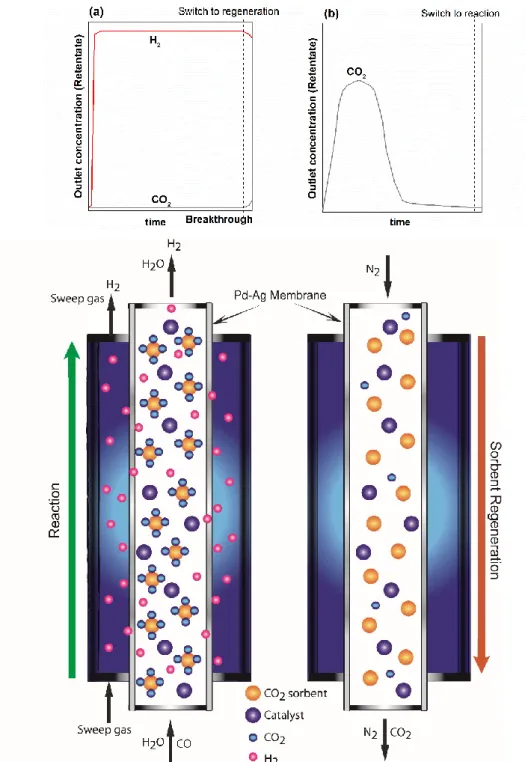
removing hydrogen and carbon dioxide from the reaction zone, respectively (Fig. 10). 426
The continuous use of such configuration would require the cyclic operation of two 427
parallel reactors (if regeneration is not longer than the production stage), producing (Fig. 428
10a)) and regenerating (Fig. 10b)) out of phase. Since the goal is to shift the 429
thermodynamic equilibrium of WGS during reaction mode by retaining CO2 in the
430
sorbent, once the sorbent gets saturated and CO2 starts breaking through the column the
431
reaction is ended (Fig. 10 (a)) and the regeneration stage is initiated (Fig. 10 (b)). The 432
main requirement is that operating conditions in both Reaction and Regenerations stages, 433
namely in terms of temperature, are compatible for the WGS catalyst, CO2 sorbent and
434
H2-selective membrane. While at lab scale N2 was used as sweep (in the membrane side)
19
and purge (for sorbent regeneration) gas, at industrial level the use of steam is preferable, 436
being also easier to separate using a simple water condenser. 437
438
4. Conclusions.
439
Results show that the presence of water vapour improves the CO2 sorption capacity of the
440
MG30-K hydrotalcite during dynamic CO2 sorption experiments. When such material is
441
submitted to CO2 sorption-desorption cycles its capacity decreases, but not significantly
442
in the presence of water vapour, and stabilizes after a few cycles. This suggests that this 443
kind of material could be used as CO2 sorbent, under the operational conditions analyzed,
444
namely in a cyclic sorption-enhanced WGS reactor. 445
The use of the SER packed with MG30-K hydrotalcite along with a Cu/ZnO-Al2O3
446
catalyst allowed that the CO conversion, in the pre-breakthrough zone, increases 447
regarding a traditional reactor; such reactor configuration also allows overcoming the 448
equilibrium conversion based on feed conditions, before CO2 breaks through the column.
449
Finally, when a multifunctional sorption-enhanced membrane reactor is used at 250 ºC 450
and 3 bar, the CO conversion increases even more. In this regard, it is possible to conclude 451
that the coexistence of both the membrane (for H2 separation) and the sorbent (for CO2
452
sorption) act simultaneously. However, at higher pressure (5.5 bar) or higher temperature 453
(300 ºC), in the pre-breakthrough zone complete CO conversion is reached, allowing to 454
obtain two hydrogen streams feasible to be fed to a fuel cell (with 100% H2 recovery).
455
This suggests that combining CO2 and H2 removal in a single unit could be beneficial for
456
the high-purity H2 production. Moreover, in the pre-breakthrough zone, the CO2 is sorbed
457
by the hydrotalcite and the CO is not produced (the equilibrium is completely shifted), 458
which is favorable for the Pd-Ag membrane since CO2 and mainly CO in gas phase can
459
poison the membrane, affecting the H2 permeability.
20 461
5. Acknowledgments
462
This work was supported by project PTDC/EQU/ERQ/098730/2008 - FCOMP-01-0124-463
FEDER-010380, financed by the European Fund for Regional Development (ERDF) 464
through COMPETE – Programa Operacional Factores de Competitividade – and by 465
national funds through Fundação para a Ciência e a Tecnologia (FCT). 466
M.A. Soria is grateful to the FCT for his postdoctoral grant (SFRH/BPD/88444/2012), 467
with financing from the European Social Fund (ESF) and the Human Potential 468
Operational Programme (POPH). 469
21
6. References
471
[1] Peña MA, Gómez JP, Fierro JLG. New catalytic routes for syngas and hydrogen production.
472
Appl Catal A: Gen 1996;144:7-57.
473
[2] Garcia La, French R, Czernik S, Chornet E. Catalytic steam reforming of bio-oils for the
474
production of hydrogen: effects of catalyst composition. Appl Catal A: Gen 2000;201:225-39.
475
[3] Abbas HF, Wan Daud WMA. Hydrogen production by methane decomposition: A review. Int
476
J Hydrogen Energy 2010;35:1160-90.
477
[4] Chesnokov VV, Chichkan AS. Production of hydrogen by methane catalytic decomposition
478
over Ni–Cu–Fe/Al2O3 catalyst. Int J Hydrogen Energy 2009;34:2979-85.
479
[5] Choudhary TV, Goodman DW. CO-free fuel processing for fuel cell applications. Catal Today
480
2002;77:65-78.
481
[6] Mendes D, Mendes A, Madeira LM, Iulianelli A, Sousa JM, Basile A. The water-gas shift
482
reaction: from conventional catalytic systems to Pd-based membrane reactors—a review.
Asia-483
Pacific Journal of Chemical Engineering 2010;5:111-37.
484
[7] Yang S-I, Choi D-Y, Jang S-C, Kim S-H, Choi D-K. Hydrogen separation by multi-bed
485
pressure swing adsorption of synthesis gas. Adsorption 2008;14:583-90.
486
[8] Lee KB, Verdooren A, Caram HS, Sircar S. Chemisorption of carbon dioxide on
potassium-487
carbonate-promoted hydrotalcite. Journal of Colloid and Interface Science 2007;308:30-39.
488
[9] Jang HM, Lee KB, Caram HS, Sircar S. High-purity hydrogen production through sorption
489
enhanced water gas shift reaction using K2CO3-promoted hydrotalcite. Chem Eng Sci
490
2012;73:431-38.
491
[10] Liguori S, Pinacci P, Seelam PK, Keiski R, Drago F, Calabrò V et al. Performance of a
492
Pd/PSS membrane reactor to produce high purity hydrogen via WGS reaction. Catalysis Today
493
2012;193:87-94.
494
[11] Mendes D, Chibante V, Zheng J-M, Tosti S, Borgognoni F, Mendes A et al. Enhancing the
495
production of hydrogen via water–gas shift reaction using Pd-based membrane reactors.
496
International Journal of Hydrogen Energy 2010;35:12596-608.
497
[12] García-García FR, Soria MA, Mateos-Pedrero C, Guerrero-Ruiz A, Rodríguez-Ramos I, Li
498
K. Dry reforming of methane using Pd-based membrane reactors fabricated from different
499
substrates. Journal of Membrane Science 2013;435:218-25.
500
[13] Mendes D, Sá S, Tosti S, Sousa JM, Madeira LM, Mendes A. Experimental and modeling
501
studies on the low-temperature water-gas shift reaction in a dense Pd–Ag packed-bed membrane
502
reactor. Chemical Engineering Science 2011;66:2356-67.
503
[14] van Dijk HAJ, Walspurger S, Cobden PD, van den Brink RW, de Vos FG. Testing of
504
hydrotalcite-based sorbents for CO2 and H2S capture for use in sorption enhanced water gas shift.
505
International Journal of Greenhouse Gas Control 2011;5:505-11.
506
[15] Martavaltzi CS, Lemonidou AA. Development of new CaO based sorbent materials for CO2
507
removal at high temperature. Microporous and Mesoporous Materials 2008;110:119-27.
508
[16] Seggiani M, Puccini M, Vitolo S. High-temperature and low concentration CO2 sorption on
509
Li4SiO4 based sorbents: Study of the used silica and doping method effects. International Journal
510
of Greenhouse Gas Control 2011;5:741-48.
511
[17] Moreira RFPM, Soares JL, Casarin GL, Rodrigues AE. Adsorption of CO2 on
512
Hydrotalcite‐like Compounds in a Fixed Bed. Separation Science and Technology
2006;41:341-513
57.
514
[18] Lee KB, Beaver MG, Caram HS, Sircar S. Reversible chemisorption of carbon dioxide:
515
simultaneous production of fuel-cell grade H2 and compressed CO2 from synthesis gas.
516
Adsorption 2007;13:385-97.
517
[19] Miguel CV, Trujillano R, Rives V, Vicente MA, Ferreira AFP, Rodrigues AE et al. High
518
temperature CO2 sorption with gallium-substituted and promoted hydrotalcites. Sep Purif
519
Technol 2014;127:202-11.
520
[20] Martunus, Othman MR, Fernando WJN. Elevated temperature carbon dioxide capture via
521
reinforced metal hydrotalcite. Microporous and Mesoporous Materials 2011;138:110-17.
22
[21] Soria MA, Pérez P, Carabineiro SAC, Maldonado-Hódar FJ, Mendes A, Madeira LM. Effect
523
of the preparation method on the catalytic activity and stability of Au/Fe2O3 catalysts in the
low-524
temperature water–gas shift reaction. Applied Catalysis A: General 2014;470:45-55.
525
[22] Tosti S, Bettinali L. Diffusion bonding of pd-ag rolled membranes. Journal of Materials
526
Science 2004;39:3041-46.
527
[23] Long Q, Xia Y, Liao S, Li Y, Wu W, Huang Y. Facile synthesis of hydrotalcite and its
528
thermal decomposition kinetics mechanism study with masterplots method. Thermochimica Acta
529
2014;579:50-55.
530
[24] Yang W, Kim Y, Liu PKT, Sahimi M, Tsotsis TT. A study by in situ techniques of the
531
thermal evolution of the structure of a Mg–Al–CO3 layered double hydroxide. Chemical
532
Engineering Science 2002;57:2945-53.
533
[25] Li X, Zhu J, Liu Q, Wu B. The removal of naphthenic acids from dewaxed VGO via
534
esterification catalyzed by Mg–Al hydrotalcite. Fuel Processing Technology 2013;111:68-77.
535
[26] Martunus, Helwani Z, Wiheeb AD, Kim J, Othman MR. Improved carbon dioxide capture
536
using metal reinforced hydrotalcite under wet conditions. International Journal of Greenhouse
537
Gas Control 2012;7:127-36.
538
[27] Walspurger S, Boels L, Cobden PD, Elzinga GD, Haije WG, van den Brink RW. The Crucial
539
Role of the K+–Aluminium Oxide Interaction in K+-Promoted Alumina- and Hydrotalcite-Based
540
Materials for CO2 Sorption at High Temperatures. ChemSusChem 2008;1:643-50.
541
[28] Das J, Das D, Parida KM. Preparation and characterization of Mg–Al hydrotalcite-like
542
compounds containing cerium. Journal of Colloid and Interface Science 2006;301:569-74.
543
[29] Ruthven DM. Principles of Adsorption and Adsorption Processes. John Wiley & Sons, New
544
York, US (1984).
545
[30] Halabi MH, de Croon MHJM, van der Schaaf J, Cobden PD, Schouten JC. High capacity
546
potassium-promoted hydrotalcite for CO2 capture in H2 production. International Journal of
547
Hydrogen Energy 2012;37:4516-25.
548
[31] Ficicilar B, Dogu T. Breakthrough analysis for CO2 removal by activated hydrotalcite and
549
soda ash. Catalysis Today 2006;115:274-78.
550
[32] Ram Reddy MK, Xu ZP, Diniz da Costa JC. Influence of Water on High-Temperature CO2
551
Capture Using Layered Double Hydroxide Derivatives. Ind Eng Chem Res 2008;47:2630-35.
552
[33] Maroño M, Torreiro Y, Cillero D, Sánchez JM. Experimental studies of CO2 capture by a
553
hybrid catalyst/adsorbent system applicable to IGCC processes. Applied Thermal Engineering.
554
[34] Tosti S, Basile A, Bettinali L, Borgognoni F, Gallucci F, Rizzello C. Design and process
555
study of Pd membrane reactors. Int J Hydrogen Energy 2008;33:5098-105.
556
[35] Miguel CV, Mendes A, Tosti S, Madeira LM. Effect of CO and CO2 on H2 permeation
557
through finger-like Pd–Ag membranes. Int J Hydrogen Energy 2012;37:12680-87.
558
[36] Tosti S, Basile A, Bettinali L, Borgognoni F, Chiaravalloti F, Gallucci F, Long-term tests
559
of Pd–Ag thin wall permeator tube, Journal of Membrane Science, 2006; 284; 393–397.
560 561 562 563 564 565 566 567 568 569
23 570 571 572 Tables 573 574 575
Table 1. Operational conditions used in tests described in section 2.3 to compare 576
traditional reactor (TR) vs. sorption-enhanced reactor (SER). 577 578 TR SER Weight of catalyst (Cu/ZnO-Al2O3) [g] 0.22 0.22 Weight of sorbent (MG30-K )[g] - 2.6 Catalyst/Sorbent weight ratio - 1/12 Wcat/QCO [g h mlN-1] 3.7 x 10⁻⁴ 3.7 x 10⁻⁴ Feed composition
CO/H2O/N2 [vol. %] 10/15/75 10/15/75
T [ºC] 250 , 300 250, 300
PT,feed [bar] 3 3
579 580
24
Table 2. Operational conditions used in tests described in section 2.4 to compare. 581
sorption-enhanced reactor (SER) vs. hybrid sorption-enhanced membrane reactor 582 (HSEMR). 583 584 SER HSEMR Weight of catalyst [g] 0.22 0.22 Weight of sorbent [g] 1.2 1.2 Catalyst/Sorbent weight ratio 1/5 1/5 Wcat/QCO [g h mlN-1] 3.7 x 10⁻⁴ 3.7 x 10⁻⁴ Feed composition
CO/H2O/N2 [vol. %] 10/15/75 10/15/75
T [ºC] 250, 300 250 , 300
PT,feed [bar] 3 3, 4 and 5.5
P = PT,feed – PT,sweep gas - ~2*
* Totalpressure difference across the membrane was not higher than 2 bar to respect the limited
585
resistance integrity of the used self-supported membrane; the sweep was always nitrogen. 586
587 588 589
Table 3. CO2 sorption capacity in dry and wet conditions (mol/kg).
590
% vol. H2O 1st cycle 2nd cycle 3rd cycle
0 0.41 0.25 0.22
5 0.48 0.42 0.39
15 0.60 0.53 0.51
25 0.65 0.51 0.48
In all cases: 15 vol. % of CO2 (balanced with N2); PT=1 bar;
591
From 3rd to the 6th cycle, the sorption capacity remains constant (data not shown).
592 593 594
25
Figures
595
596
Fig.1. Scheme of the hybrid sorbent-membrane reactor.
597 598
26 599
Fig.2. TG/DTG/DSC profiles for the MG30-K promoted hydrotalcite.
600 601 602
603
Fig. 3. Experimental breakthrough curves obtained with the MG30-K hydrotalcite at different total
604
pressures (PT; ( • ) 1 bar, (• ) 2 bar and (• ) 3 bar). T = 300 ºC, feed composition =15 vol.% of CO2 and
605
balance N2, total flow rate = 100 mlN/min .
606 607
27 608
Fig 4. Experimental breakthrough curves obtained with the MG30-K hydrotalcite at different CO2 feed
609
compositions (•) 15 vol.% of CO2 in N2 and (•) 10 vol.% of CO2 in N2. T = 300 ºC, PT= 1 bar, total flow
610 rate = 100 mlN/min. 611 612 613 614 615 616 617 618
Fig.5. Regeneration behavior in dry conditions; variation of the relative CO2 concentration and sorption
619
capacity as a function of the sorption time and cycles number of the MG30-K hydrotalcite. Sorption 620
conditions: PT= 1 bar, T=300 ºC, total flow rate = 100 mlN/min and feed composition= 15 vol. % of CO2 in
621
N2. Desorption conditions: PT= 1 bar, T= 300 ºC and 100 mlN/min of N2.
622 623
28 624
Fig. 6. Breakthrough curves in three consecutive sorption-desorption cycles and corresponding sorption
625
capacities (inset) in presence of water vapour. Sorption conditions: T = 300 ºC, PT = 1 bar, 15 vol. % of
626
CO2 and 15 vol. % of H2O balanced with N2. Desorption conditions: T = 300 ºC, PT = 1 bar and 100 mlN/min
627
of N2.
628 629 630
29 631
632
Fig. 7. CO conversion and CO and CO2 composition (vol. %) history during WGS reaction in a traditional reactor at A) 300 ºC and B) 250 ºC and
633
in a sorption-enhanced reactor at C) 300 ºC and D) 250 ºC. See Table 1 for additional operating conditions. 634
30
635
636
Fig. 8. CO conversion and CO and CO2 composition (vol. %) history during WGS reaction in a sorption-
637
enhanced reactor at A) 300 ºC and 3 bar and in a hybrid sorbent-membrane reactor at B) 300 ºC and 3 bar, 638
C) 300 ºC and 4 bar and D) 300 ºC and 5.5 bar. See Table 2 for additional operating conditions.
639 640
31 641
Fig. 9. CO conversion and CO and CO2 composition (vol. %) history during WGS reaction in a sorption-
642
enhanced reactor at A) 250 ºC and 3 bar and in a hybrid sorbent-membrane reactor at B) 250 ºC and 3 bar 643
and C) 250 ºC and 5.5 bar. See Table 2 for additional operating conditions. 644
645 646
32 647
Fig. 10 - Schematic view of the conceived HSEMR based on 2 parallel reactors configuration for continuous
648
operation and corresponding outlet concentrations histories in the retentate stream during (a) reaction and 649
(b) regeneration stages. 650