José Alberto Moreira e Silva
Arm TrustZone: Evaluating the
Diversity of the Memory Subsystem
Julho de 2019
José Alberto Moreira e Silva
Arm TrustZone: Evaluating the
Diversity of the Memory Subsystem
Dissertação de Mestrado em Engenharia Eletrónica
Industrial e Computadores
Trabalho efectuado sob a orientação do
Professor Doutor Sandro Pinto
Julho de 2019
Este é um trabalho académico que pode ser utilizado por terceiros desde que respeitadas as regras e boas práticas internacionalmente aceites, no que concerne aos direitos de autor e direitos conexos. Assim, o presente trabalho pode ser utilizado nos termos previstos na licença abaixo indicada.
Caso o utilizador necessite de permissão para poder fazer um uso do trabalho em condições não previstas no licenciamento indicado, deverá contactar o autor, através do RepositóriUM da Universidade do Minho.
Atribuição-CompartilhaIgual CC BY-SA
Acknowledgements
”How do you pick up the threads of an old life? How do you go on, when in your heart you begin to understand there is no going back?”. Returning to the regular places and occupations after learning that life has drastically changed and will never go back to what it used to proved to be as difficult as described by Tolkien. As this work finishes, so does a chapter of life which was so far the hardest to let go, but thanks to a number of people, it can now be seen as a learning experience for what the future may hold, and for all of them I am thankful for impacting my life and getting me here. There are although some that I must refer to personally.
Firstly I’d like to thank my advisor, Sandro Pinto, for always being comprehensive and helping guide the elaboration of this work, always allowing me to put myself first and finish late instead of never completing this work. Secondly, a word of appreciation to José Martins, for sharing his knowledge and experience in the early stages of this work and helping getting over some initial humps in the road.
To all of the colleagues at the ESRG lab—Ailton, Ângelo, Francisco, Hugo, José, Nuno, Pe-dro, Ricardo and Sérgio—always ready to lend a helping hand whenever someone needed it, I’m grateful for growing and improving alongside such great people. To the three old friends that have known me for almost as long as myself, thank you for being present, specially during this last year, and may the weekend company last for as long as possible.
Lastly, I have to thank my family for everything they have done to help me get to where I am today. Specially to my parents and sisters, I am forever grateful for being the support system I needed to get through life so far. When all other things came crashing down, you were the ones making sure I did not go along with the rubble, and for that I will always love you all.
I hereby declare having conducted this academic work with integrity. I confirm that I have not used plagiarism or any form of undue use of information or falsification of results along the process leading to its elaboration.
Abstract
The diversification of the embedded market has led the once single-purpose built embedded device to become a broader concept that can accommodate more general-purpose solutions, by widening its hardware and software resources. A huge diversity in system resources and requirements has boosted the investigation around virtualization technology, which is becoming prevalent in the embedded systems domain, allowing timing and spatial sharing of hardware and software resources between specialized subsystems. As strict timing demands imposed in real-time virtualized systems must be met, coupled with a small margin for the penalties incurred by conventional software-based virtualization, resort to hardware-assisted solutions has become indispensable.
Although not a virtualization but security-oriented technology, Arm TrustZone is seen by many as a reliable hardware-based virtualization alternative, with the low cost and high spread of TrustZone-enabled processors standing as strong arguments for its acceptance. But, since Trust-Zone only dictates the hardware infrastructure foundations, providing SoC designers with a range of components that can fulfil specific functions, several key-components and subsystems of this technology are implementation defined. This approach may hinder a system designer’s work, as it may impair and make the portability of system software a lot more complicated.
As such, this thesis proposes to examine how different manufacturers choose to work with the TrustZone architecture, and how the changes introduced by this technology may affect the security and performance of TrustZone-assisted virtualization solutions, in order to scale back those major constraints. It identifies the main properties that impact the creation and execution of system software and points into what may be the most beneficial approaches for developing and using TrustZone-assisted hardware and software.
Resumo
A recente metamorfose na área dos sistemas embebidos transformou estes dispositivos, outrora concebidos com um único e simples propósito, num aglomerado de subsistemas prontos para integrar soluções mais flexíveis. Este aumento de recursos e de requisitos dos sistemas potenciou a investigação em soluções de virtualização dos mesmos, permitindo uma partilha simultânea de recursos de hardware e software entre os vários subsistemas. A proliferação destas soluções neste domínio, onde os tempos de execução têm de ser respeitados e a segurança é um ponto-chave, tem levado à adoção de técnicas de virtualização assistidas por hardware.
Uma tecnologia que tem vindo a ser utilizada para este fim é a Arm TrustZone, apesar de inicialmente ter sido desenvolvida como uma tecnologia de proteção, dado a sua maior presença em placas de médio e baixo custo quando comparada a outras tecnologias. Infelizmente, dado que a TrustZone apenas fornece diretrizes base sobre as quais os fabricantes podem contruir os seus sistemas, as especificações da tecnologia divergem de fabricante para fabricante, ou até entre produtos com a mesma origem. Aliada à geral escassez de informação sobre esta tecnologia, esta característica pode trazer problemas para a criação e portabilidade de software de sistema dependente desta tecnologia.
Como tal, a presente tese propõe examinar, de uma forma sistematizada, de que forma difer-entes fabricantes escolhem implementar sistemas baseados na arquitetura TrustZone e em que medida as mudanças introduzidas por esta tecnologia podem afetar a segurança e desempenho de soluções de virtualização baseadas na mesma. São identificadas as principais características que podem influenciar a criação e execução de software de sistema e potenciais medidas para diminuir o seu impacto, assim como boas práticas a seguir no desenvolvimento na utilização de software e hardware baseados na TrustZone.
Contents
List of Figures xii
List of Tables xiii
List of Listings xiv
Glossary xv
1 Introduction 1
1.1 Motivation . . . 2
1.2 Goals . . . 3
1.3 Document Structure . . . 4
2 Background and Related Work 5 2.1 Virtualization . . . 5 2.2 Arm Architecture . . . 8 2.2.1 Armv7-A . . . 11 2.2.2 Armv8-A . . . 20 2.3 Arm TrustZone . . . 28 2.3.1 TrustZone Architecture . . . 28 2.3.2 TrustZone-assisted Virtualization . . . 32 2.4 Related Work . . . 37
3 Platform and Tools 40 3.1 TrustZone-enabled platforms . . . 40
3.1.1 ZYBO Zynq-7000 . . . 41
3.1.3 ZCU102 Evaluation Board . . . 45
3.1.4 RaspberryPi 3B . . . 48
3.2 LTZVisor . . . 49
3.2.1 Architectural Overview . . . 49
3.2.2 Implementation Overview . . . 51
3.2.3 Modifications to the LTZVisor . . . 53
4 TrustZone Memory Subsystem: Main Memory 59 4.1 TrustZone-enabled IP . . . 59 4.2 SoC Implementations . . . 62 4.2.1 Zynq-7000 . . . 62 4.2.2 i.MX6 . . . 64 4.2.3 UltraScale+ . . . 66 4.3 Discussion . . . 68 4.3.1 Granularity . . . 69 4.3.2 Dynamic Configurations . . . 70 4.3.3 Security Inversion . . . 71 4.3.4 Access Permissions . . . 72
5 TrustZone Memory Subsystem: MMU/Caches 73 5.1 Two Address Spaces . . . 73
5.2 TrustZone-aware Caches . . . 76
5.2.1 Eviction Policy . . . 78
5.2.2 Maintenance Operations . . . 80
5.2.3 Interaction with TrustZone-IP . . . 81
5.2.4 Discussion . . . 82
6 Conclusion 86 6.1 Future Work . . . 88
References 89
List of Figures
2.1 System Stack Approaches . . . 6
2.2 Hypervisor Classification . . . 7
2.3 Arm architecture evolution . . . 10
2.4 Armv7-A Core Registers . . . 14
2.5 Two-level Address Translation . . . 15
2.6 VMSA Access Hierarchy . . . 16
2.7 Armv7-A Page Table Layout . . . 17
2.8 Armv7-A Privilege Levels . . . 21
2.9 Armv8-A Exception Levels . . . 22
2.10 Armv8-A General-Purpose Registers . . . 24
2.11 Armv8-A Special Registers . . . 24
2.12 Armv8-A VMSA . . . 26
2.13 Arm TrustZone Architecture . . . 29
2.14 TrustZone-IP Example Layout . . . 32
2.15 Arm TrustZone Software Stack . . . 33
2.16 Single-Guest Virtualization Typology . . . 34
2.17 Dual-Guest Virtualization Typology . . . 35
2.18 Multi-Guest Virtualization Typology . . . 36
2.19 CacheKit Architecture . . . 38
3.1 Zynq-7000 SoC Block Diagram . . . 42
3.2 i.MX6 DualLite SoC Overview . . . 44
3.3 Zynq Ultrascale+ MPSoC Block Diagram . . . 47
3.4 LTZVisor Architecture . . . 50
4.1 TrustZone Memory Adapter . . . 60
4.2 TrustZone Address Space Controller Regions . . . 61
4.3 ZYBO TrustZone Support for OCM and DDR . . . 64
4.4 i.MX6 OCM TrustZone Support . . . 65
4.5 i.MX6 DDR TrustZone Support . . . 66
4.6 XMPUs in the Ultrascale+ Architecture . . . 68
5.1 TrustZone-aware Address Translation Process . . . 74
5.2 TrustZone-aware TLB . . . 75
5.3 TrustZone-aware Caches . . . 76
5.4 Example of a cache-based attack . . . 79
List of Tables
2.1 Armv7-A Processor Modes . . . 13
2.2 Armv7-A Exception Vector Tables . . . 19
2.3 Armv8-A Exception Vector Tables . . . 27
4.1 SoC Implementations Summary . . . 69
5.1 TLB Maintenance Operations From Different Sources . . . 75
5.2 Cache Maintenance Operations From Different Sources . . . 80
List of Listings
3.1 LTZVisor Monitor Exception Vector Table . . . 54
3.2 Example Abort Handler written in C . . . 54
3.3 Page Table Descriptors Assembly Macros . . . 56
3.4 Page Table Definition for i.MX6 Board . . . 56
Glossary
AMBA Advanced Microcontroller Bus Architecture
APB Advanced Peripheral Bus
APU Application Processing Unit
APU Application Processor Unit
AXI Advanced eXtensible Interface
COTS Commercial of-the-shelf
CPU Central Processing Unit
CSU Central Security Unit
DMA Direct Memory Access
DRAM Dynamic Random-Access Memory
FIQ Fast Interrupt Request
FPGA Field Programmable Gate Array
GIC Generic Interrupt Controller
GPOS General-Purpose Operating System
IoT Internet of Things
IP Intellectual Property
IPA Intermediate Physical Address
IRQ Interrupt Request
LTZVisor Lightweight TrustZone-assisted Hypervisor
MMU Memory Management Unit
NS Non-secure
OCM On-chip Memory OS Operating System PA Physical Address PL Programmable Logic PR Partial Reconfiguration PS Processing System
RTOS Real-Time Operating System
SMC Secure Monitor Call
SoC System on-Chip
SPSR Saved Program Status Register
SVC Supervisor Call
TCB Trusted Computing Base
TLB Translation Lookaside Buffer
TTBR Translation Table Base Register
TZ TrustZone
TZASC TrustZone Address Space Controller
TZMA TrustZone Memory Adapter
TZPC TrustZone Protection Controller
USB Universal Serial Bus
VA Virtual Address
VE Virtualization Extensions
VM Virtual Machine
VMCB Virtual Machine Control Block
VMM Virtual Machine Monitor
XMPU Xilinx Memory Protection Unit
XPPU Xilinx Peripheral Protection Unit
1. Introduction
The diversification of the embedded market, prompted by the expansion of industries such as consumer electronics and the more recent incursion of Internet-of-Things solutions, has led the once single-purpose built embedded device to become a broader concept. These platforms can now accommodate more general-purpose solutions by widening its hardware and software resources. Furthermore, coupling multiple subsystems in the same platform does not only reduce costs, by promoting resource sharing among components, but also increases performance, as the tightly coupled subsystems can communicate a lot faster.
As a way of consolidating the multiple isolated subsystems into the same hardware platform, virtualization technology is becoming prevalent in the embedded systems domain, allowing timing and spatial resource sharing between subsystems by enabling the implementation of heteroge-neous software environments into the same platform. This trend can be seen in industries such as the automotive industry, where real-time, safety-critical functionalities are integrated with the infotainment environment (Kim et al., 2013, Lee et al., 2016, Reinhardt and Morgan, 2014), or the aerospace industry, where virtualization provides isolation for safety-critical components (Mas-mano et al., 2009, Pinto et al., 2016b). In both cases, a Real-time Operating System (RTOS) and a General Purpose Operating System (GPOS) are each encapsulated in what is called a Virtual Machine (VM), which has a virtualized view of the system resources. This resource abstraction allows monitoring software—a Virtual Machine Monitor (VMM)—to manage VM communication to system components and among each other, in order to guarantee timing and spatial isolation between VMs. As strict timing demands imposed in real-time virtualized systems must be met, coupled with a small margin for the penalties incurred by conventional software-based virtualiza-tion, resort to hardware-assisted solutions is imperative and becoming the norm.
2 Chapter 1. Introduction Among existing commercial of-the-shelf (COTS) technologies, such as Intel’s Virtualization Technology (VT), Arm Virtualization Extensions (VE) and Arm TrustZone (TZ), the latter is assert-ing itself in the virtualization realm. Although not a virtualization but security-oriented technology, TrustZone is seen by many as a reliable hardware-based virtualization alternative (Frenzel et al., 2010, Pinto et al., 2019, 2016a, 2017b, Sangorrin et al., 2010). The lower cost and higher spread of TrustZone-enabled processors, in comparison with VE-enabled processors, along with the fact that TrustZone is considered the only implementable hardware-based virtualization approach on non-VE Arm processors, are standing as strong arguments for this solution’s acceptance. More-over, due to the introduction of TrustZone technology in the new generation of Cortex-M processors (ARM, 2017b), the technology is poised to make its mark in the low-end sector (Pinto et al., 2019), revealing the prospect for virtualization in embedded devices that are more resource-constrained. As System on Chip (SoC) manufacturers continue to develop TrustZone compliant devices, this technology is becoming ingrained in the embedded market (ARM, 2018c). But, since Trust-Zone only provides the hardware infrastructure foundations, allowing a SoC designer to choose from a range of components that can fulfil specific functions within the target environment (ARM, 2009b), it means that a lot of the technology is implementation defined. This approach may hinder a system designer’s work, as it may impair and make the portability of system software (Operating Systems, Hypervisors) developed with this technology a lot more complicated since, for example, different target platforms may provide more or less options to control its memory subsystem, as well as lead to some design idiosyncrasies that should be accounted for (Zhang et al., 2016a). As such, it is important to examine how different manufacturers choose to work with the TrustZone architecture, in order to scale back those major constraints.
1.1
Motivation
This master’s thesis was developed to help shed some light into the TrustZone world, mainly the memory subsystem, of which information is rather scarce and superficial. With the current existence of TrustZone-enabled virtualization solutions, it becomes relevant to take a step back
and evaluate how the implementation-defined facet of this technology may influence the devel-opment of these solutions, as well as answering some questions that are left pending by the available TrustZone literature. Developed within the Embedded System Research Group (ESRG) of the University of Minho, it takes advantage of the existence of an in-house TrustZone-assisted hypervisor, the LTZVisor, and the current porting efforts for its deployment in various development boards, to evaluate the diversity and intricacies of the TrustZone memory subsystem in different platforms.
1.2
Goals
The main goals of this thesis are to survey and identify the main differences in separate implementations of TrustZone-aware memory subsystems, and how these may impact the ex-ecution and porting of system software. Furthermore it intends to study the impact that some design choices of this technology may have on the security and performance of TrustZone-assisted virtualization environments.
To accomplish these goals, a smaller set of objectives can be laid out:
• Study of the Arm architecture and TrustZone-assisted virtualization, for a better
contextu-alization of the research environment;
• Review and evaluation of different SoC implementations of TrustZone memory subsystems,
identifying the main attributes whose variance most influences the development of system software;
• Review and evaluation of the TrustZone modifications to the cache architecture, its benefits
and drawbacks to the implementation of virtualized environments.
After the initial study, the evaluation of the different approaches designers follow when build-ing a system that complies with the TrustZone architecture will identify the advantages they brbuild-ing over each other and the drawbacks associated with each one. The targeted platforms (Xilinx Zynq-7000, Xilinx Zynq Ultrascale +, RaspberryPi3, i.MX6) are representative of different price ranges
4 Chapter 1. Introduction from big-name manufacturers/vendors in the embedded market (EETimes and Embedded.com, 2017), which provide a somewhat broad view of the embedded landscape.
1.3
Document Structure
Including this introductory chapter that contextualizes the motivation behind the work, this document is divided into six chapters. Chapter 2 presents the underlying concepts necessary to the development of this thesis, reviewing the virtualization concept, Arm’s architectural features as well as the TrustZone extensions and their use in the deployment of virtualization solutions. Chapter 2 concludes by shortly reviewing some works that helped identify some of the questions this thesis aims to answer. Chapter 3 presents the hardware platforms that were subject to evalu-ation and the runtime environment, LTZVisor, that was deployed in those platforms to perform the review of the different implementations. Chapters 4 and 5 present the results of the surveying processes of the main memory subsystem of the selected boards and TrustZone’s cache-level implementations, respectively. Chapter 6 displays the main summary of the results drawn in the two preceding chapters, bringing together the conclusions from both angles, providing a more holistic view of the impacts they may present.
2. Background and Related Work
This chapter exposes the most pertinent subjects for the development of this thesis and reviews works that are closely related to the core of research. The concept of virtualization is introduced, followed by an overview of the Arm architecture and the Arm TrustZone extensions. Some works that provide an overview of the TrustZone technology are then reviewed for a deeper contextualization of this thesis focus.
2.1
Virtualization
Virtualization can be seen as the emulation of a host system into multiple isolated virtual machines (VMs) which mimic the behaviour of the host. A VMM, also known as an hypervisor, is responsible for configuring and maintaining the VM environment, running at the highest privilege level and multiplexing accesses from the VMs to the hosting system resources.
Despite being around since the 60’s, it was not until a couple of decades ago that virtualiza-tion became a relevant topic in both research and commercial environments. Initially developed as a way to improve utilization of hardware resources on platforms that previously could only run a single application/Operating System at a time (Graziano, 2011), virtualization got out of focus for the research community when the availability of multitasking and multi-user OSes became more widespread. Its resurgence took place when, mainly in the increasingly connected world of desktop and server domains, challenges of resource management and isolation became a con-cern that prompted research for a better solution than fixing all scalability bottlenecks present in general purpose OSes (Kauer, 2014). Using virtualization to tackle this problem allows concur-rent execution of multiple VMs to increase the utilization rates of underlying resources while also
6 Chapter 2. Background and Related Work providing VM isolation and encapsulation. Isolation ensures that concurrent VMs cannot tamper with each others data/execution flow while encapsulation allows saving of a VMs current state, making it possible to run at another time or even in a different host machine. Figure 2.1 depicts the architectural differences between the classical approach of single guest per host system and the virtualized approach in which a single host allows execution of multiple guest VMs.
Host Platform Guest OS App Guest OS App Host Platform Guest OS App Host Platform Guest OS App Guest OS App Host Platform Guest OS App Host Platform Guest OS App Guest OS App Host Platform Guest OS App Host Platform Guest OS App Guest OS App Host Platform Guest OS App
(a) Classical Approach
Virtualization Layer - VMM Host Platform VM Guest OS App VM Guest OS App VM Guest OS App VM Guest OS App VM Guest OS App VM Guest OS App VM Guest OS App VM Guest OS App (b) Virtualization Approach
Figure 2.1: System Stack Approaches
Traditionally, guests are unaware of their virtualization, in an approach called full-virtualization. This allows running unmodified OSes, which is crucial when dealing with OSes whose source code is not available but comes with a drawback in terms of performance and increased complexity. This is due to traditional trap-and-emulate or Dynamic Binary Translation techniques which require constant execution mode crosses and excessive use of memory resources. The trap-and-emulate techniques require that the hypervisor identifies when guests attempt to access critical registers or restricted memory locations, trapping those instructions, and then emulating the effect they would trigger, without actually executing them on the host, which greatly increases the hypervisor’s workload.
Differently to full-virtualization, para-virtualization relies on changing guest OSes source code, introducing hypercalls that implicitly invoke the hypervisor for execution of critical instructions. This comes at a high engineering cost and is not always a viable solution, given the availability of
guest source code, but, when applicable, greatly minimizes the performance overhead imposed by classical approaches by reducing the hypervisors’ workload. This approach also eases the process of memory management in a virtualized system since the guests can be aware of their memory boundaries at compile time and, as such, can prevent accesses to memory locations that belong to other guests, maintaining the isolation between guest partitions.
Independently of the virtualization approach, it is possible to distinguish two types of hypervi-sors based on the position of the virtualization layer in the software stack (Figure 2.2):
• Type-1, or bare-metal Hypervisors, have direct access to the hardware layer and manage
the execution permissions of every system component, mediating all hardware accesses. As a consequence, the performance degradation of guest OSes will only be influenced by the performance of the Hypervisor itself, making this type of Hypervisor more suited to systems with strict time constraints.
• Type-2, or hosted Hypervisors, run over a OS that is already executing rather than directly
above the hardware layer. This type of VMM usually does not have permissions to access and perform any operation on the hardware directly, since those responsibilities usually rest in the system software that runs below the VMM, leading to lower performance ratings compared to type-1 Hypervisors.
Hardware Hypervisor
OS OS OS
(a) Type-1 Hypervisor
Hardware OS Hypervisor OS OS OS OS OS OS OS OS OS Hypervisor OS OS OS (b) Type-2 Hypervisor
8 Chapter 2. Background and Related Work Fulfilling the growing need to consolidate multiple isolated subsystems into the same hardware platform in fields such as the automotive (Kim et al., 2013, Lee et al., 2016, Reinhardt and Morgan, 2014) and aerospace (Masmano et al., 2009, Pinto et al., 2016c) industries, this shift towards virtualized environments is also becoming prevalent in the embedded systems world, mainly through type-1 hypervisors. As the strict timing demands imposed in real-time virtualized systems must be met, coupled with a small margin for the penalties incurred by conventional software-based virtualization, resort to hardware-assisted solutions is becoming the norm. Among other things, virtualization hardware extensions—e.g. Arm’s Virtualization Extensions (VE) (Varanasi and Heiser, 2011) or Intel’s Virtualization Technology (Uhlig et al., 2005)—reduce overhead in context switch operations and eliminate some of the trapping of guest accesses by creating a new hypervisor privilege mode and introducing banking of sensitive registers between execution modes. Crucially, they also provide two-level address translation hardware support, speeding the translation from guest-virtual to host-physical address, which is essential when implementing a full-virtualization environment.
Although these hardware extensions are starting to make their way into the mid to high-end processors realm, propelled in a big way by the recent proliferation of Arm processors in this market, it is worth mentioning one other set of more widespread extensions developed by Arm. The Arm TrustZone extensions, initially deployed with security as its main target, implement similar register banking between privilege modes and have been shown to provide a virtualization solution in devices that do not possess hardware virtualization extensions (Frenzel et al., 2010, Pinto et al., 2017b, Sangorrin et al., 2010), enabling the integration of virtualized environments in a wider range of platforms.
2.2
Arm Architecture
In the past few years, Arm has helped build the technology that redefined industries ranging from mobile and consumer devices to networking and servers, cementing its position has a major force in the embedded market and in the Internet of Things (IoT) world. Arm licenses its processor architectures and intellectual property (IP) blocks—deployed in silicon to enhance/accelerate, for
example, security or graphics—to SoC manufacturers wishing to develop reliable and connected devices. Currently, Arm-based chips account for 39% of the ”chips with processors” market share and growing, with 90% of the processors in mobile application processors or controllers for IoT devices being Arm-based (ARM, 2018c).
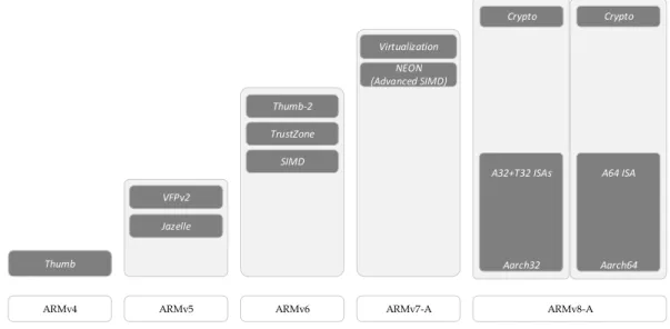
Previously known as Advanced RISC Machine, Arm represents a family of Reduced Instruc-tion Set Computing (RISC) architectures which implements a small set of simple and general instructions, contrasting with a Complex Instruction Set Computing (CISC) architecture, which im-plements more complex and differentiated instructions. Traditionally, differences between these architectures allowed for lower cost, power consumption and heat dissipation values in RISC processors (Blem et al., 2013), fitting the needs of smaller, portable, battery-powered devices present in the embedded or mobile computing realms. Arm builds up on the base RISC 32-bit load/store architecture and enhances it by implementing features such as conditional execution of instructions to reduce branching and improve code density, auto incrementing and decrement-ing addressdecrement-ing modes that optimize program loops and load/store multiple data instructions to maximize data throughput (Goodacre and Sloss, 2005). All of these changes, along with the addiction of the reduced Thumb instruction set optimized for code density, with improved perfor-mance in narrower 16-bit memory systems, promoted the growth of Arm in the low to mid-end devices market, which is still prevalent to this day. Arm kept continually improving its architec-ture, adding new functionalities to the existing ones as the application processors requirements kept evolving, but maintaining its core characteristics like the different processor modes, general-purpose registers and program status registers. The most relevant additions to each version of the base architecture are depicted in Figure 2.3, such as the introduction of Single Instruction Multiple Data (SIMD) or the TrustZone security extensions and the virtualization extensions (ARM, 2005).
More recently, reflecting Arm’s goal of becoming relevant in different markets which present distinct challenges and requirements, variations of the base architecture were introduced, to which Arm called architecture profiles. This differentiation of processor architectures allows manufac-turers to comply with the current Size, Weight, Power and Cost (SWaP-C) requirements of modern
10 Chapter 2. Background and Related Work
ARMv8-A
Thumb
Jazelle VFPv2
ARMv4 ARMv5 ARMv6 ARMv7-A
TrustZone SIMD Thumb-2 NEON (Advanced SIMD) Virtualization Crypto Crypto A32+T32 ISAs Aarch32 A64 ISA Aarch64
Figure 2.3: Arm architecture evolution
devices without compromising performance or determinism in systems where those are crucial. Chip manufacturers can choose between different profiles for the one which better fits their needs or even combine them, implementing a flexible system fit for a myriad of applications, without having the fear of consolidation issues between the modules. Currently, and since the unveiling of the Armv7 architecture, Arm provides three of these architectural variants and in-house processor core families called ”Cortex” that are compliant with each of these profiles:
• Application profile: Armv7(8)-A processors, such as Cortex-A cores, implement a
tradi-tional Arm architecture and support a virtual memory system architecture based on a Memory Management Unit (MMU). This is the highest performance profile, influenced by multi-tasking OS system requirements, and is usually found in applications such as smart-phones, tablets and digital televisions.
• Real-time profile: Armv7(8)-R processors, such as Cortex-R cores, implement a traditional
Arm architecture similarly to the previous profile but support a protected memory system architecture based on an Memory Protection Unit (MPU) instead of the virtual memory approach followed by ”-A” processors. As with the application processes, they provide high performance and throughput but with very precise timing and predictable interrupt latency, making them ideal for deeply embedded time-critical applications.
• Microcontroller profile: Armv7(8)-M processors, such as Cortex-M cores, implement a
pro-grammers’ model designed for fast interrupt processing, with hardware stacking of regis-ters and support for writing interrupt handlers in high-level languages. Intended for use in microcontrollers, they follow a minimalistic implementation when compared to the other profiles, which allows for low cost and low power values, characteristic of these types of devices.
As depicted above, these variants are available in both the Armv7 and the latest Armv8 ar-chitecture which, at the moment, are the two main Arm arar-chitectures in the market. Despite having an enormous presence in the mobile/smartphone industry (ARM, 2018c), the Armv8 ar-chitecture has not yet hit the embedded market in a meaningful way, where 64-bit devices are not very widespread, which boost the proliferation of Armv7 devices (EETimes and Embedded.com, 2017).
The following two subsections describe the Armv7-A and Armv8-A architectures, for a better understanding of the Arm architecture for application profiles, as these are the two architectures present in the boards subject to evaluation, in the form of Cortex-A9 and Cortex-A53 cores. In the context of this thesis, the covered subjects are narrowed to the processor modes, register organization, memory architecture and exception handling of the two architectures.
2.2.1
Armv7-A
Armv7, the seventh version of the 32-bit Arm architecture, was the first version to implement the distinction between three architectural profiles: the application profile, the real-time profile and the microcontroller profile. This section focuses on the application profile, Armv7-A, developed fo high-processing low power applications, such as smartphones or digital televisions, supporting a virtual memory system based on an MMU. Out of the three profiles, the application profile differs the least from the previous Armv6 architecture, building upon it while increasing capability and performance.
The following subsections present an overview of the Armv7-A architecture, in an implemen-tation that includes both the TrustZone and virtualization extensions. Although the virtualization
12 Chapter 2. Background and Related Work extensions are not considered in the scope of this work, including them here allows a better comparison with the Armv8-A architecture.
2.2.1.1 Processor Modes
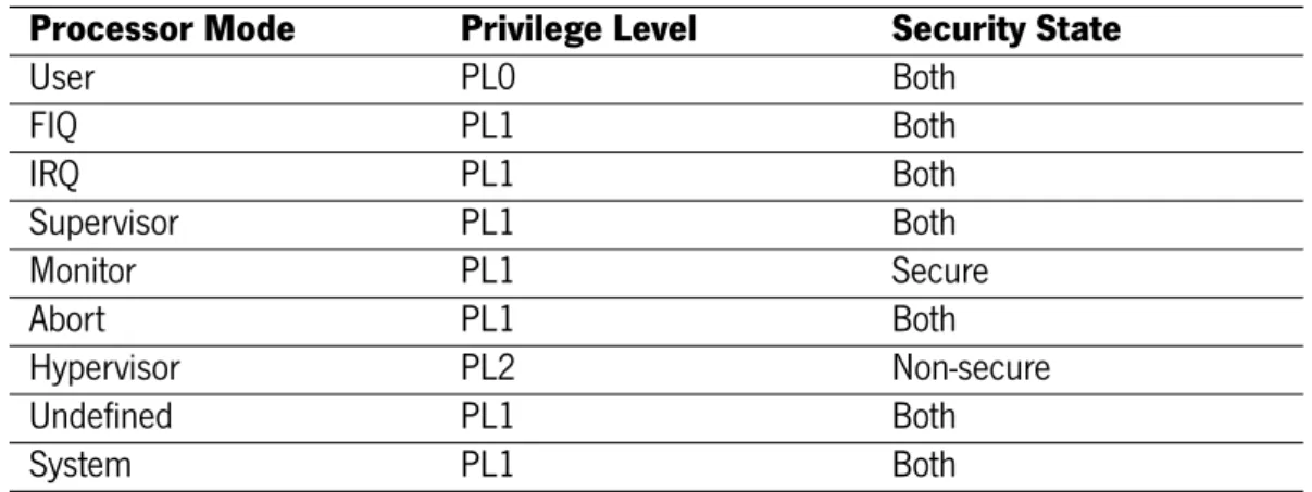
In an implementation that includes both the security and virtualization extensions, the Armv7-A architecture adds two processor modes to the seven present in Armv7-Armv6 (Armv7-ARM, 2005, 2012). The nine modes—User, System, Supervisor, Abort, Undefined, FIQ, IRQ, Hypervisor and Monitor—are split between privilege levels and security states. There are three privilege levels—PL0,PL1 and PL2— orthogonal to the security state, with the exception of the Hypervisor and Monitor modes which are assigned to the non-secure and secure states, respectively, as displayed in Table 2.1. The privilege levels refer to the permissions that software running at a certain level has over system resources in the current security state:
• PL0, where only User Mode runs, is considered the unprivileged level, allowing no access
to system configuration registers. This is usually where OS applications that do not belong to the kernel run.
• PL1, where software has access to all system resources except for a few virtualization
configuration registers added in the virtualization extensions. This is usually where OS software is executed. In this level, all modes except monitor mode can run in both security states.
• PL2, dedicated to the Hypervisor mode, is designed for virtual machine managing
soft-ware and only runs in a non-secure state. Softsoft-ware executing at PL2 can perform all the operations available at PL1, plus some additional functionalities.
It is important to note that privilege level and security state are two independent concepts. The security extensions are further explained in section 2.3 but the main note to have present is that non-secure software cannot change configurations or control settings for secure operations, even in PL2, but secure software can meddle with non-secure operations. Permissions can be
Table 2.1: Armv7-A Processor Modes
Processor Mode Privilege Level Security State
User PL0 Both FIQ PL1 Both IRQ PL1 Both Supervisor PL1 Both Monitor PL1 Secure Abort PL1 Both Hypervisor PL2 Non-secure Undefined PL1 Both System PL1 Both
assigned: at PL1, for accesses made by PL1 or PL0; at PL2 for non-secure accesses made by PL2 or non-secure accesses made by PL1 or PL0.
Changing processor mode can be achieved in three different ways: either privilege software explicitly changes the current processor mode or an exception is being handled or returned from (See Section 2.2.1.4). Changes from User mode can only occur by causing an exception, which is handled in a specific mode at a higher level, dependent of system configurations. Entering Hypervisor mode can only be achieved by taking an exception from non-secure PL0 or PL1 modes or returning from an exception being handled in Monitor mode. As for the PL1 modes, any of them can explicitly change the processor mode to another PL1 mode or to User mode.
2.2.1.2 Registers
Armv7-A maintains the general register layout of past versions, with thirteen general-purpose registers (R0-R12) and a Program Counter (PC) shared among all processor modes—except for the FIQ mode which has its own R8-R12 registers—, along with a Linker Register (LR), Stack Pointer (SP) and Saved Program Status Register (SPSR). These last three registers are banked between almost all processing modes, meaning that each mode has its own physical copy of the register, as displayed in (ARM, 2012, Figure 2.4), where the white cells represent the registers which are shared amongst all modes. When an exception is taken, the preferred return address is transferred to the banked LR register and the CPSR of the mode running when the exception was triggered is saved in the SPSR of the mode to which the exception was taken. This creates
14 Chapter 2. Background and Related Work
B1 The System Level Programmers’ Model B1.3 ARM processor modes and ARM core registers
B1-1144 Copyright © 1996-1998, 2000, 2004-2012 ARM. All rights reserved. ARM DDI 0406C.b
Non-Confidential ID072512
Figure B1-2 ARM core registers, PSRs, and ELR_hyp, showing register banking
As described in Processor mode for taking exceptions on page B1-1172, on taking an exception the processor changes mode, unless it is already in the mode to which it must take the exception. Each mode that the processor might enter in this way has:
• A Banked copy of the stack pointer, for example SP_irq and SP_hyp. • A register that holds a preferred return address for the exception. This is:
— for each PL1 mode, a Banked copy of the link register, for example LR_und and LR_mon — for the PL2 mode, Hyp mode, the special register ELR_hyp.
• A saved copy of the CPSR, made on exception entry, for example SPSR_irq and SPSR_hyp. In addition FIQ mode has Banked copies of the ARM core registers R8 to R12.
User mode and System mode share the same ARM core registers. User mode, System mode, and Hyp mode share the same LR.
For more information about the application level view of the SP, LR, and PC, and the alternative descriptions of them as R13, R14 and R15, see ARM core registers on page A2-45.
Pseudocode details of ARM core register operations
The following pseudocode gives access to the ARM core registers: // The names of the Banked core registers.
enumeration RName {RName_0usr, RName_1usr, RName_2usr, RName_3usr, RName_4usr, RName_5usr, RName_6usr, RName_7usr, RName_8usr, RName_8fiq, RName_9usr, RName_9fiq, RName_10usr, RName_10fiq, RName_11usr, RName_11fiq, RName_12usr, RName_12fiq, RName_SPusr, RName_SPfiq, RName_SPirq, RName_SPsvc,
RName_SPabt, RName_SPund, RName_SPmon, RName_SPhyp, RName_LRusr, RName_LRfiq, RName_LRirq, RName_LRsvc, APSR R12 SP LR PC R11 R10 R9 R8 R7 R6 R5 R4 R3 R2 R1 R0
‡ Part of the Security Extensions. Exists only in Secure state.
User System Supervisor Abort Undefined IRQ FIQ
R0_usr R1_usr R2_usr R3_usr R4_usr R5_usr R6_usr R7_usr R8_usr R9_usr R10_usr R11_usr R12_usr SP_usr LR_usr PC CPSR
SPSR_svc SPSR_abt SPSR_irq SPSR_fiq
LR_svc LR_abt LR_irq LR_fiq
SP_svc SP_abt SP_irq SP_fiq
R8_fiq R9_fiq R10_fiq R11_fiq R12_fiq LR_und SP_und SPSR_und SPSR_mon LR_mon SP_mon Application
level view System level view
SP_hyp
SPSR_hyp
† Part of the Virtualization Extensions. Exists only in Non-secure state. ELR_hyp
Cells with no entry indicate that the User mode register is used.
Hyp Monitor
Figure 2.4: Armv7-A Core Registers
an easier mechanism to return from exceptions, relieving the workload of the context restore. These Program Status Registers (PSRs) store information such as the carry and overflow condition flags, the endianess, the execution state—Arm, Thumb or Jazelle—and the processor mode. Other system configurations regarding security and virtual memory are controlled through Arm’s coprocessors, mainly CP15. These are only accessible by software running at PL1, with variable security permissions—registers can be secure access only, shared between both states, banked between both states and some have a configurable security access. This separation is further explored in section 2.3.
2.2.1.3 Memory Architecture
As previously mentioned, Armv7-A processors implement a Virtual Memory System Architec-ture (VMSA) based on a MMU, supporting the existence of level-1 (L1) and level-2 (L2) caches (ARM, 2012). In a VMSA implementation, all the addresses generated by the processor are Virtual Addresses (VA), enabling each kernel or user process to run in its own virtual memory space. This allows the concurrent execution of multiple processes atop of the same physical memory, through a process of address relocation which translates a virtual address issued by the processor into a physical address in main memory. In a classical implementation, a multitasking OS manages
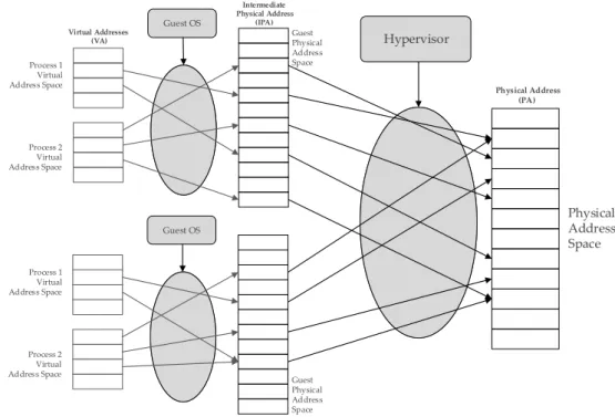
each task’s memory system view, switching the mappings when a task starts executing. In a virtualized system, in a two-level address translation implementation, another layer is added. So, the hypervisor manages each guest OS system view which then manages the tasks’ translation regime. Figure 2.5 helps illustrate this concept—in a non-virtualized system, the guest physical address space would correspond to the real physical address space and the translation process would stop there.
Process 1 Virtual Address Space Process 2 Virtual Address Space Guest Physical Address Space Guest OS Process 1 Virtual Address Space Process 2 Virtual Address Space Guest Physical Address Space Guest OS Physical Address Space Hypervisor Virtual Addresses (VA) Intermediate Physical Address (IPA) Physical Address (PA)
Figure 2.5: Two-level Address Translation
The unit responsible for this translation process between the virtual memory view and the real physical memory addresses is the MMU. Carried out by the MMU hardware, this process is trans-parent to the task issuing the virtual addresses, meaning that the task needs no knowledge of the underlying physical memory system mapping or the mappings used by other tasks. To translate these addresses, the MMU uses a set of translation tables which contain the mappings between virtual and physical addresses, along with memory access permissions and cache policies for each region of memory. When a virtual address is issued, the MMU uses the information in the translation tables to check if the access is valid and, if so, return the corresponding physical ad-dress, in a process called translation table walking. As these translation tables are usually stored
16 Chapter 2. Background and Related Work in main memory, which take some time to access, Arm implements a set of ”translation caches”, called Translation Lookaside Buffers (TLBs), which store recently executed translations. This ac-cess hierarchy is represented in (ARM, 2014, Figure 2.6). Note that the Caches block displayed in the figure may hold entries from the translation tables and not the result of the translation itself, which can only be cached in the TLBs.
The Memory Management Unit
ARM DEN0013D Copyright © 2011 – 2013 ARM. All rights reserved. 9-3
ID012214 Non-Confidential
9.1
Virtual memory
The MMU enables you to build systems with multiple virtual address maps. Each task can have its own virtual memory map. The OS kernel places code and data for each application in physical memory, but the application itself does not require the location.
The address translation carried out by the MMU is done using translation tables. These are tree-shaped table data structures created by software in memory, that the MMU hardware traverses to accomplish virtual address translation.
Note
In the ARM architecture, the concept referred to in generic computer terminology as page tables has a more specific meaning. The ARM architecture uses multi-level page tables, and defines
translation tables as a generic term for all of these. An entry in a translation table contains all
the information required to translate a page in virtual memory to a page in physical memory. The specific mechanism of traversal and the table format are configurable by software and are explained later.
Translation table entries are organized by virtual address. In addition to describing the translation of that virtual page to a physical page, they also provide access permissions and memory attributes necessary for that page.
Figure 9-2 The Memory Management Unit
Addresses generated by the core are virtual addresses. When the MMU is enabled all memory accesses made by the core pass through it. The MMU essentially replaces the most significant bits of this virtual address with some other value, to generate the physical address (effectively defining a base address of a piece of memory).The same translation tables are used to define the translations and memory attributes that apply to both instruction fetches and to data accesses. Dedicated hardware within the MMU enables it to read the translation tables in memory. This process is known as translation table walking.
9.1.1 Configuring and enabling the MMU
Before the MMU is enabled, the translation tables must be written to memory. The TTBR register must be set to point to the tables. The following code sequence can then be used to enable the MMU:
MRC p15, 0, R1, c1, C0, 0 ;Read control register
ORR R1, #0x1 ;Set M bit
MCR p15, 0,R1,C1, C0,0 ;Write control register and enable MMU
Care must be taken if enabling the MMU changes the address mapping of the region in which code is currently being executed. Barriers (See Memory barriers on page 10-6) may be necessary to ensure correct operation.
ARM Core Caches
TLBs Table Walk Unit MMU Translation tables Memory
Figure 2.6: VMSA Access Hierarchy
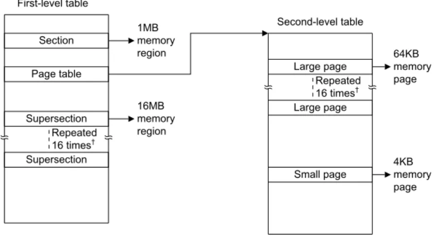
Armv7-A, as a 32-bit architecture, spans a 4GB addressable physical space. Stage-1 trans-lation tables, which translate virtual to physical addresses, split this 4GB into 4096 equal sized sections, each describing 1MB block of virtual memory space. Each of these 32-bit sized entries can describe pages of four different sizes: a supersection (16MB block of memory), a section (1MB block of memory), a large page (64KB block of memory) or a small page (4KB block of memory). The supersection and section entries define the base address of a contiguous 16 or 1MB section, respectively. On the other hand, small or large page entries point to a level 2 trans-lation table, which allows subdividing a 1MB region into smaller pages, as displayed in Figure 2.7. The levels of translation tables should not be confused with the stages of translation where stage-1 refers to virtual to intermediate physical address translations (VA-IPA) and stage-2 to intermediate physical to physical address translations (IPA-PA).
Setting the base address of the stage-1 translations tables is done by writing to the Translation Table Base Register (TTBR), for stage-1 translations in every mode other than the hypervisor mode. For stage-1 translations from hypervisor mode, the Hypervisor Translation Table Base Register (HTTBR) is used. The stage-2 translation table base address is set by the Virtualization Translation Table Base Register (VTTBR), which is only accessible from hypervisor mode or monitor mode.
Chapter 2. Background and Related Work 17
ARM DDI 0406C.b Copyright © 1996-1998, 2000, 2004-2012 ARM. All rights reserved. B3-1325
ID072512 Non-Confidential
Figure B3-3 gives a general view of address translation when using the Short-descriptor translation table format.
Figure B3-3 General view of address translation using Short-descriptor format translation tables
Additional requirements for Short-descriptor format translation tables on page B3-1328 describes why, when using the Short-descriptor format, Supersection and Large page entries must be repeated 16 times, as shown in
Figure B3-3.
Short-descriptor translation table format descriptors, Memory attributes in the Short-descriptor translation table format descriptors on page B3-1328, and Control of Secure or Non-secure memory access, Short-descriptor format on page B3-1330 describe the format of the descriptors in the Short-descriptor format translation tables.
The following sections then describe the use of this translation table format:
• Selecting between TTBR0 and TTBR1, Short-descriptor translation table format on page B3-1330
• Translation table walks, when using the Short-descriptor translation table format on page B3-1331.
B3.5.1 Short-descriptor translation table format descriptors
The following sections describe the formats of the entries in the Short-descriptor translation tables: • Short-descriptor translation table first-level descriptor formats on page B3-1326
• Short-descriptor translation table second-level descriptor formats on page B3-1327.
For more information about second-level translation tables see Additional requirements for Short-descriptor format translation tables on page B3-1328.
Note
Previous versions of the ARM Architecture Reference Manual, and some other documentation, describes the AP[2] bit in the translation table entries as the APX bit.
Information returned by a translation table lookup on page B3-1320 describes the classification of the non-address fields in the descriptors as address map control, access control, or attribute fields.
Section 1MB memory region Page table Supersection 16MB memory region Second-level table Large page 64KB memory page Small page 4KB memory page Supersection Repeated 16 times† Repeated 16 times† First-level table Large page
Figure 2.7: Armv7-A Page Table Layout
With the inclusion of the virtualization extensions, Armv7-A processors present four MMU interfaces, each with their own enable controls: secure PL1 and PL0 stage-1 MMU is controlled by the System Control Register MMU bit, SCTLR.M, in the secure copy of the register; non-secure PL1 and PL0 stage-1 MMU is controlled by SCTLR.M, in the non-secure copy of the register; non-secure PL1 and PL0 stage-2 MMU is controlled by the Hypervisor Configuration Register, HCR.VM, accessible only at PL2; non-secure PL2 stage-1 MMU is controlled by the Hypervisor System Control Register, HSCTLR.M, also only accessible at PL2. Disabling any of these instances means that the generated address remains unaltered but does not guarantee that the memory attributes or permissions are not set (ARM, 2012).
Latest versions of the Armv7-A architecture specification also introduced the Large Physical Address Extensions (LPAE), to support higher levels of device integration on a single memory and space under a single address space (ARM, 2011b). This allows the mapping of multiple 32-bit virtual address spaces into up to a 40-bit physical address space, solving some of the 4GB limitations present in 32-bit addressable systems.
2.2.1.4 Exception Handling
An exception causes the processor to suspend program execution to handle an event, such as an externally generated interrupt or an attempt to execute an undefined instruction. When an exception is taken in Armv7-A, the processor state is immediately preserved, before handling the exception, so that the original state can be restored upon exception return. This concept was
18 Chapter 2. Background and Related Work introduced in Section 2.2.1.1, where the linker register, stack pointer and SPSR were saved upon entering a new processing mode.
In this exception model, five types of exceptions are defined: reset, undefined instructions, system calls, memory aborts and interrupts. Arm takes these five types and implements nine different exceptions, incorporated in the security and virtualization extensions:
• Reset: When the reset input is asserted, the processor stops execution until that input
is no longer driven. Execution is then resumed in secure Supervisor mode at the proper address defined in SCTLR.V.
• Undefined Instruction: Occurs whenever an instruction with undefined or invalid behavior
tries to execute. This illegal execution can be the result of disabled coprocessor operations or unimplemented instructions for the current instruction set state.
• Supervisor Call (SVC): This instruction explicitly launches an exception that causes the
processor to enter Supervisor mode. Typically, the SVC instruction is executed to request an operating system function.
• Secure Monitor Call (SMC): Part of the security extensions, this instruction causes the
processor to enter Monitor mode.
• Hypervisor Call (HVC): Implemented with the virtualization extensions, the HVC instruction
causes the processor to enter Hypervisor mode.
• Prefetch Abort: Triggered by a memory abort on an instruction fetch, usually generated by
the MMU permission checking. By default this exception is taken to Abort mode but can be modified to change into Monitor or Hypervisor modes.
• Data Abort: Taken on a read or write memory access abort generated by the MMU or
when a memory access external to the core generates an access error, such as a TrustZone security error. As with the Prefetch Abort, it can be handled in Abort, Monitor or Hypervisor modes.
• IRQ: Triggered by asserting an IRQ interrupt request input to the processor. Similar to the
Abort exceptions, it is taken by default to the IRQ mode but can also be handled in Monitor or Hypervisor modes.
• FIQ: Alike the IRQ exception, it is triggered by asserting an IRQ interrupt request input to
the processor and can also be handled in FIQ, Monitor or Hypervisor modes, depending on system configuration.
Out of all the exceptions mentioned above, it is important to note that the IRQ, FIQ and Data Abort exceptions can be masked using the Current Program Status Register. Masking them means that those exceptions will not be taken until they are no longer masked, which is useful when executing critical tasks that demand determinism and isolation. There is also another exception which has not been mentioned yet, the Hyp Trap. This is reserved for the virtualization extensions and is only taken when non-secure software running in any mode other than Hypervisor mode executes an instruction that traps in Hypervisor mode.
Handling exceptions in Armv7-A forces execution to an address that corresponds to the type of exception, referred to as the exception vector of that exception (ARM, 2012). These exception vectors are organized in four vector tables, assigned to the Hypervisor mode, the Monitor mode and the Secure and Non-secure states of the PL1. Each of these tables contains eight entries corresponding to specific exceptions’ exception vector, organized as displayed in Table 2.2.
Table 2.2: Armv7-A Exception Vector Tables
Offset Hypervisor Monitor Secure Non-secure
0x00 — — Reset —
0x04 Undefined Inst. — Undefined Inst. Undefined Inst.
0x08 HVC SMC SVC SVC
0x0C Prefetch Abort Prefetch Abort Prefetch Abort Prefetch Abort 0x10 Data Abort Data Abort Data Abort Data Abort
0x14 Hyp Trap — — —
0x18 IRQ IRQ IRQ IRQ
0x1C FIQ FIQ FIQ FIQ
Usually a system programmer writes a branch instruction at these addresses that jumps to a more complex handler of the exception being taken. The base address to which these offsets
20 Chapter 2. Background and Related Work are relative to is saved in variations of the Vector Base Address Register (VBAR). The secure and normal worlds have banked copies of this register, accessible at PL1, while the HVBAR and the MVBAR respectively hold the Hypervisor and Monitor exception vector tables base address.
2.2.2
Armv8-A
Armv8 is the latest version of the Arm architecture and the first to implement a 64-bit archi-tecture. The introduction of the Armv8-A architecture does not intend to tackle current limitations in application processors but to pave the way for designs that will support tomorrow’s applications (ARM, 2017a). As previously mentioned, contemporary solutions in the embedded market still heavily rely on the Armv7-A architecture, boosted by the addition of the Large Physical Address Extensions which help solve the limitations of 4GB physical address spaces. As with all version of its architecture, Arm tries to maintain as much backwards compatibility possible, easing porting efforts to the new architectures. The two execution states implemented in Armv8-A are a reflection of this view:
• Aarch32 retains the Armv7 32-bit approach and maintains its definitions of privilege levels,
allowing the execution of A32 or Thumb instruction sets.
• Aarch64 introduces the A64 instruction set with 64-bit general-purpose registers along with
a new approach to privileged execution.
The following sections will focus on the innovations introduced in Armv8-A and, as such, are centered around the Aarch64 execution state. The division between these topics is homologous to the one made in the Armv7-A review, to facilitate a comparison between the two. As with section 2.2.1, matters such as the instruction set and interrupt management are not covered, as they are out of the scope for the development of this thesis.
2.2.2.1 Exception Levels
One of the biggest changes introduced in Armv8-A is the refactoring of the privileged execution model. When the virtualization extensions were introduced to Armv7-A, with the addiction of PL2,
separation of mode and privilege level became even more confusing than with the addition of monitor mode in TrustZone. As displayed in (ARM, 2015, Figure 2.8), monitor mode, used for switching between the secure and normal worlds, was the most privileged execution mode in Armv7-A but ran at the same privilege level as all other ”privileged modes”. Being placed in PL1 and with more privilege than PL2 was also counter-intuitive, not very clear from a numbering standpoint.
User Mode
Normal World Secure World
System mode Supervisor mode FIQ mode IRQ mode Undefined mode Abort mode Hypervisor mode User Mode System mode Supervisor mode FIQ mode IRQ mode Undefined mode Abort mode Monitor Mode PL1 PL2 PL1 PL0
Figure 2.8: Armv7-A Privilege Levels
With the introduction of Armv8-A, monitor mode evolved into an exception level, EL3, with its own memory translation regime and interrupt vectors. This allowed for cleaner separation of code, making it easier to provide separate binary images for switching and service implementation (ARM, 2018b). This change into exception levels was also translated to the other processor modes, which disappear in Armv8-A, while the previous implemented privilege levels are translated into the new exception level model:
• EL0, where non-privileged software runs, usually refers to user-level applications of an OS. • EL1, where OS kernel management and operations execute, in a privileged manner. • EL2, reserved for the execution of an hypervisor, solely implemented in non-secure state.
22 Chapter 2. Background and Related Work
• EL3, where the Secure Monitor now resides, in charge of switching between secure and
normal worlds.
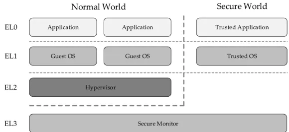
A typical software stack for systems deployed in Armv8-A processors is represented in (ARM, 2015, Figure 2.9), where the privilege hierarchy and separation is well defined and easily com-prehended from an holistic point of view. As with Armv7-A, the now exception levels refer to the permissions that software running at a certain level has over system resources in the current security state. This applies to all ELs except the EL2 which can only access non-secure resources and the EL3 which can access all system resources at all time.
Application
Normal World Secure World
Guest OS Hypervisor Trusted Application Trusted OS Secure Monitor EL1 EL2 EL3 EL0 Application Guest OS
Figure 2.9: Armv8-A Exception Levels
Changes to the current exception level can be divided into two categories: raising to a higher privilege level or lowering to a less privileged level. Transitions to a higher exception level can only be achieved when handling an exception. These exceptions can either be the result of an internal or external event or through explicit execution of one of three system calls: a Supervisor Call (SVC), an Hypervisor Call (HVC) or a Secure Monitor Call (SMC). Supervisor calls are used by software running in EL0 to trigger a raise to EL1 and are usually executed by user applications wishing to use specific OS services. Hypervisor calls can be executed by software running in non-secure EL1, raising the exception level to EL2. Secure Monitor calls can be issued by software running at either EL1 or EL2, triggering a switch to EL3. SMC can also be trapped into EL2 when executed
from non-secure EL1 if the HCR_EL2.TSC bit is set. Transitions to a lower exception level are the result of executing an ERET instruction which restores the execution state according to the Saved Program Status Register (SPSR). As with Armv7-A, this register saves the current processor state—condition flags, executions state, exception level— when an exception is taken and, along with the linker register storing the address to return to, enables a quick context restoring process.
2.2.2.2 Registers
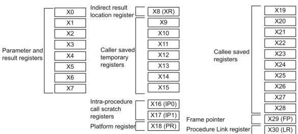
The shift to 64-bit processing and elimination of processor modes is reflected in the register organization changes introduced in Armv8-A. The new architecture is supported by thirty one 64-bit general purpose registers which are common to every exception level. In order to maintain compatibility with the Aarch32 execution mode, each of these registers can be accessed in one of two ways with the usage of a prefix. Using the ”X” prefix gives access to the full 64-bit register while accesses executed with the ”W” prefix can only affect the least significant thirty two bits of that register. As such, these registers range from X0-X30 or W0-W30, depending on the pretended address resolution. Out of the thirty general purpose registers, Arm’s Application Binary Interface (ABI) for the 64-bit architecture defines X0-X7 as argument registers, doubling the amount of registers available for passing parameters in comparison to Armv7-A, reducing the need to spill parameters to the stack (ARM, 2017a, Figure 2.10). Registers X29 and X30 are also defined as the Frame Pointer register (FP) and Link Register (LR). None of these registers are banked between exception levels, which means that saving the general purpose register context between exception levels must be explicitly done by software.
Apart from these registers, Armv8-A also implement a set of ”special registers” (ARM, 2017a, Figure 2.11). Two of them, the program counter (PC) and the zero register (XZR,WZR), are shared among all exception levels. The program counter in Armv8-A shifts away from the Armv7-A im-plementation, where it was considered a general purpose register, and is no longer accessible for explicit operations. The zero register is a register that reads as zero when used as a source register and discards the result when used as a destination register. Remaining special registers are split among the exception levels. Any of the Saved Program Status Registers (SPSR_ELx) can
24 Chapter 2. Background and Related WorkThe ABI for ARM 64-bit Architecture
ARM DEN0024A Copyright © 2015 ARM. All rights reserved. 9-4
ID050815 Non-Confidential
Figure 9-1 General-purpose register use in the ABI
9.1.2 Indirect result location
To reiterate, the X8 (XR) register is used to pass the indirect result location. Here is some code: //test.c// struct struct_A { int i0; int i1; double d0; double d1; } AA;
struct struct_A foo(int i0, int i1, double d0, double d1) {
struct struct_A A1; A1.i0 = i0; A1.i1 = i1; A1.d0 = d0; A1.d1 = d1; return A1; } void bar() { AA = foo(0, 1, 1.0, 2.0); }
and that can be compiled using:
armclang -target aarch64-arm-none-eabi -c test.c fromelf-c test.o X16 (IP0) X0 X1 X2 X3 X4 X5 X6 X7 X8 (XR) X9 X10 X11 X12 X13 X14 X15 Frame pointer Procedure Link register Parameter and result registers Indirect result location register X17 (IP1) X18 (PR) X19 X20 X21 X22 X23 X24 X25 X26 X27 X28 X29 (FP) X30 (LR) Caller saved temporary registers Intra-procedure call scratch registers Platform register Callee saved registers
Figure 2.10: Armv8-A General-Purpose Registers
be accessed in any exception level equal or above the ”x” level. For example, SPSR_EL1 can be accessed at EL1, EL2 and EL3 but not at EL0. EL0 does not possess a SPSR or a ELR since these registers are used to restore processor state when returning from an exceptions, which does not happen at EL0. As for the stack pointer, in any EL except EL0 both the current EL stack pointer or the SP_EL0 can be chosen as the stack pointer.
ARMv8 Registers
ARM DEN0024A Copyright © 2015 ARM. All rights reserved. 4-3
ID050815 Non-Confidential
4.1 AArch64 special registers
In addition to the 31 core registers, there are also several special registers.
Figure 4-3 AArch64 special registers
Note
There is no register called X31 or W31. Many instructions are encoded such that the number 31 represents the zero register, ZR (WZR/XZR). There is also a restricted group of instructions where one or more of the arguments are encoded such that number 31 represents the Stack
Pointer (SP).
When accessing the zero register, all writes are ignored and all reads return 0. Note that the 64-bit form of the SP register does not use an X prefix.
In the ARMv8 architecture, when executing in AArch64, the exception return state is held in the following dedicated registers for each Exception level:
• Exception Link Register (ELR).
• Saved Processor State Register (SPSR).
There is a dedicated SP per Exception level, but it is not used to hold return state. Special
registers Stack pointer
Zero register Program counter
EL0 EL1 EL2 EL3
Program Status Register Exception Link Register
XZR/WZR SP_EL0 PC SP_EL1 SPSR_EL1 ELR_EL1 SP_EL2 SPSR_EL2 ELR_EL2 SP_EL3 SPSR_EL3 ELR_EL3
Table 4-1 Special registers in AArch64 Name Size Description
WZR 32 bits Zero register XZR 64 bits Zero register WSP 32 bits Current stack pointer SP 64 bits Current stack pointer PC 64 bits Program counter
Table 4-2 Special registers by Exception level
EL0 EL1 EL2 EL3
Stack Pointer (SP) SP_EL0 SP_EL1 SP_EL2 SP_EL3
Exception Link Register (ELR) ELR_EL1 ELR_EL2 ELR_EL3
Saved Process Status Register (SPSR) SPSR_EL1 SPSR_EL2 SPSR_EL3
Figure 2.11: Armv8-A Special Registers
Regarding system configuration, which was previously controlled through the use of copro-cessors, mainly CP15, Armv8-A implements different system registers throughout the execution levels that control various configurations. Akin to the special registers mentioned above, system register’s names are extended with ”_ELx” which indicates the lowest exception level at which a register can be accessed. Some registers only exist in certain exception levels, but are still extended with the same suffix, such as the SRC_EL3 register or virtualization registers tagged with the EL2 suffix. It is also important to note that even though a register may only differ in the
ELx suffix, functionalities of system registers assigned to lower exception levels do not have, most of the times, as many functionalities as the ones only accessible at higher exception levels.
2.2.2.3 Memory Architecture
The Virtual Memory System Architecture of an Armv8-A processor is, from a top-level view-point, similar to an Armv7-A processor implementation with virtualization and large physical ad-dress extensions, given the presence of two-level translation support and capability for physical address mapping above 4GB. Although implementing some different granule sizes and address-able bit depths, the main differences arise with the addition of the exception levels and in nomen-clature standardization to minimize confusion.
In Armv7-A, monitor mode, which ran at PL1, had the same system view as any other pro-cessor mode running at PL1 in a secure state. The translation table base register (TTBR) used for stage-1 translations was banked between the secure and normal worlds but common to all processor modes. In Armv8-A, the base address for stage-1 translation tables are given by the TTBR0_EL1 or TTBR1_EL1 registers, which can be used by processes running at EL0 or EL1. Now supporting a 48-bit physical address memory map, selection between these two registers is based on the first sixteen bits of the 64-bit virtual address generated by the processor, which must be all 0s or 1s, otherwise triggering a fault (ARM, 2015). In AArch64 these registers are not banked between the secure and normal worlds and, as such, secure monitor code must manage tables for the both worlds, saving and restoring copies of TTBR0_EL1 and TTBR1_EL1. As for the stage-2 translations, which convert an intermediate physical address to a physical address, an ex-tra set of tables is used, under control of the hypervisor. These only apply to non-secure EL0/EL1 accesses made by VMs managed by the VMM. The base register for the stage-2 translation ta-ble is specified in the Virtualization Translation Tata-ble Base Register (VTTBR0_EL2). The overall Armv8-A VMSA architecture is illustrated in (ARM, 2015, Figure 2.12), where the possible trans-lation regime hierarchies are displayed along with the registers which configure the transtrans-lation tables base addresses.