Sadek C. A. Alfaro
Member, ABCM
[email protected] Automation and Control Group – GRACO The University of Brasilia Brasília, DF, Brazil
Paul Drews
[email protected] European Mechatronic Centre, APS/RWTH Aachen, GERMANY
Intelligent Systems for Welding
Process Automation
This paper presents and evaluates the concept and implementation of two distinct multi-sensor systems for the automated manufacturing based on parallel hardware. In the most sophisticated implementation, 12 processors had been integrated in a parallel multi-sensor system. Some specialized nodes implement an Artificial Neural Network, used to improve photogrammetry-based computer vision, and Fuzzy Logic supervision of the sensor fusion. Trough the implementation of distributed and intelligent processing units, it was shown that parallel architectures can provide significant advantages compared to conventional bus-based systems. The paper concludes with the comparison of the main aspects of the transputer and the DSP-based implementation of sensor guided robots.
Keywords: Welding process, multi-sensor system, parallel processing, automation,
artifi-cial neural network
Introduction
For the automation of complex manufacturing systems, a great deal of progress came up in the last decade, with respect to precision and on-line documentation (bases for the quality control), (Starke 1983, Strunz 1993, Fuchs et al, 1993, Kovacevic & Zhang 1997). With the advent of electrically driven mechanical manipulators and later the whole, relatively new, multidisciplinary mechatronic engi-neering, the need of information acquisition has increased. The acquisition is, in many cases, distributed trough the system, with strong interaction between the robot and its environment. The de-sign objective is to attain a flexible, lean production. The require-ment of real time processing of data from multi-sensor systems with robustness, in industrial environment, shows the need for new con-cepts on system integration.1
A Multi-sensor system represents neither the utilization of many sensors with the same physical nature nor many independent meas-urement systems, but mainly sensor fusion, the extraction of global information coming from the interrelation data given by each sen-sor. Some examples are the estimation of the slope of any surface using two or three individual sensors, the simultaneous acquisition of the parameters of the automatic welding process MIG/MAG ("Metal Inert Gas/ Metal Active Gas") or the direct observation of the welding pool related to the control of current, voltage, wire speed and torch welding speed.
This paper will present and compare the results of the imple-mentation of two multi-sensor system based on parallel architecture. (Alfaro et al 1997 and Bauchspiess, 1995).
This paper points out the efficiency of distributed multi-sensor systems in automation of manufacturing processes using robots. The acquired expertise in industrial welding robots and in hydraulic robots both guided by optical sensors is evaluated and compared. In the first case, Transputers were used and in the second case DSP's, forming a digital signal processing net for the processing distribu-tion in the manufacture automadistribu-tion. The sensor fusion concept employing Artificial Neural Networks pattern recognition and Fuzzy Logic supervision were implemented on specialized distributed processing units.
Automation of Processes with Distributed Processing.
The data to be processed for process control in the case of a multisensor system are, by nature, parallel and decentralized. Those data appear without a consistent temporal interrelation in many points of the process, sometimes simultaneously or displaced in time. There is no coupling among sensors and those can acquire new
Paper accepted August, 2005. Technical Editor: Edgar Nobuo Mamiya.
data in an autonomous way. Consequently the distributed processing is the most suitable in this case.
This characteristics lead to the problem of measurement interre-lation of individual sensors for giving significant global information, the so called sensor fusion (Kam et al 1997). Conventional systems based on bus, with the typical problems between Master and Slave, have deep restrictions concerning computational performance (Hwang 1993, Alexander et al 1996). It seems that, in this case, it is appropriate to use parallel architectures which, in modular and stepping form, is adequate to the specific problem, without the need for relevant changes in hardware.
As in many typical industrial applications, the reason for using parallel processing was the possibility of processing distribution in a simple and cheap way, allowing also future expansions in a natural way, for upgrading the characteristics of this architecture. The choice of processors used was made based on computational per-formance and cost. Massively Parallel Computing, as refered in many high-end applications (Krikelis & Lea 1996), was not taken into consideration here for parallel processing, because in process automation fine granularity is often not given (Hwang 1993).
In the following sections, two robotic systems will be presented: a welding cell guided by sensors and a hydraulic manipulator for heavy load.
A Sensor Guided Welding Cell
The main tasks in welding automation are the guiding of the ro-bot movements, allowing the welding torch to be always inside the welding joint and controlling the welding parameters such as cur-rent, voltage, wire feed rate, heat input, etc.
For the control of welding processes, in an integrated intelligent welding cell, developed at European Centre of Mechatronic-Aachen, a video system has been coupled to the torch, for direct observation of the welding pool and a sensor for optical seam tracking (scanner) put in front of the torch ("look-ahead"). The main goal was the acquisition and processing of all the information of the welding process in the same way that a welder would do it. Figure l shows a diagram of the physical construction of the sensor system and its main functions.
A Sensor Guided Hydraulic Manipulator
For many processes, the power required for the manipulator to transport heavy load could only be supplied trough hydraulic driv-ers. Typically, hydraulic robots have a weight to load ration of 1:5
Optical Scanner
CCD-Camera Welding
Torch
Visualization Robot Control
Welding Equipment
Melting Pool Geometry
Joint and Seam Geometry
x x x xxx xx xx x x x xx xxx
xx x xx x x x x
Process Parameters
Interface: Motion and Process Control
Global Data Processing
Evaluation,
Interrelation, Mo
nitoring
Figure 1. Set up and functional main units of the multi-sensor welding system.
and, in the other hand, for electric driven robots the usual ratio is about 1:35 (ABB 1991). Those systems show, from the point of view of control, big difficulties, due to the extremely non-linear characteristics of this type of drivers. Nevertheless, modern control techniques such as the highest derivative control and the exact lin-earization, act together with the availability of high computational performance allowing drifting this drawback of hydraulic drivers and reach the requirement precision (Bauchspiess, 1995). To study different control strategies for hydraulic systems, an hydraulic ma-nipulator with two degrees of freedom was constructed at IRT-Erlangen. The open architecture of this system allows evaluating different control techniques without the usual difficulties found in commercial industrial robots. Both the joint control and sensor guided path tracking could be exhaustively studied. Particularly the path model based predictive servocontrol (FMP - Following Model Predictive), proved excellent tracking performance, offsetting virtu-ally the track error typical of intrinsicvirtu-ally inert mechanical systems (Bauchspiess 1997).
The Components of the Sensor Guided Welding Cell
The parallel processing system for manufacturing at APS-Aachen ("ParMan - Parallel Manufacturing System") is based on a parallel processing architecture. The technology used was a Tran-sputer T805 and the hybrid system T805/MC601. A PC was used as host and for the process visualization over a user friendly interface.
The connection of the individual sensors is done trough tran-sputer links, providing practically a 1,6 Mbytes/s transmission rate. Each sensor allows rates around 150 bytes per read and a maximum of 25 reads per second.
The Welding Joint Sensor
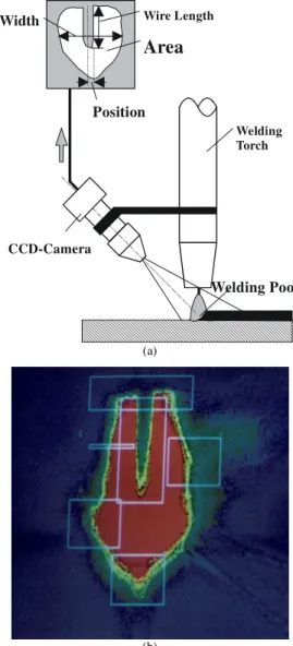
A system of optical sensoring has been developed in order to al-low the gathering of information about the geometry of the welding joint, aiming to set right the position of the welding torch, as well as the control of the welding process. This system uses, as
measure-ment principle, triangulation scanning to obtain the shape of the gap in the welding joint (Drews & Willms 1996). (Figure 2)
CCD-Camera
Welding Torch
Welding Pool
Wire Length
Area
Position
Width
(a)
(b)
Figure 2. (a) Set up and (b) obtained typical image of the welding pool.
It was important to develop the data acquisition system with a high measurement confidence (noise rejection). So, two triangula-tion procedures for acquisitriangula-tion of the distance of the welding plate in each scanning were used. This special construction allows com-pensation of imperfections in data caused by shadows in the surface topology or by the influence of reflection conditions. In comparison with a 3D measurement system that uses a CCD-camera and a striper laser light projected by cylindrical lens (Alfaro et al 1997) or by a holographic grid, the actual proposed system shows much higher noise protection, because all the laser power is focused in only one light spot. According to the quality of the received signal (diffuse reflection, opaque surface etc.), light intensity adaptation can be made. The signal conditioning and the control of the sensor have been implemented by the parallel processing architecture shown in Figure 3.
at the end, the welding joint geometry. At this point, different mod-ules were developed, that can be used for different types of welding joints using prior knowledge.
U vD
S PS U I Wfs GF RC D0 D1 D2 D3 D4 D5 User
Interface
Robot Control
Data Management
Weldign Pool Inspection
Seam
Geometry Equipment Control Welding
Digital I/O AD / DA
Sensor 1 Sensor 2 Sensor 3
Figure 3. Parallel multi-sensor system “ParMan“, indicating employed transputer nodes.
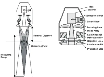
Moreover, the Master decides which of the two values of dis-tance (or a combination of both) can be used as disdis-tance signal after a plausibility evaluation. With this sensor, measurements can be obtained at frequencies up to 20 Hz. (Figure 4)
Figure 4. Joint welding sensor set up (real view).
To supervise this vision system, a Fuzzy Logic based System was used to determine if the welding torch was inside the welding joint. If the system does not do this, the whole analytical processing is meaningless. 27 Rules relating Slope (S), Bend (B) and Slope time derivate (dS/dt) were established to represent the knowledge of an experienced welder (Drews & Trier 1994).
Box Scanner
Deflection Mirror
Focusing Lens Laser Diode
Light Channel Diode Array
Deflection Mirro
Protection Glas Interference File Objective Lens Nominal Distance
Measuring Field
Measuring Range
Figure 4. Joint welding sensor set up (detailed view).
The Welding Power Source Operation
The power source operation involves monitoring signals and generating commands over the AD/DA interface; this signals are protected against welding current interference by opto-couplers. Processing capability and high transmission rates were not neces-sary. Nevertheless, the parallel driving of channels by T222 Tran-sputers simplified the implementation.
The Components of the Hydraulic System
The hydraulic manipulator-was built using aluminum profiles, in order to keep the robot weight as low as possible. The nominal load at the TCP that can be carried at 2m/s is 30Kg. An hydraulic aggre-gate furnishes a 150 bar oil pressure to feed the hydraulic cylinders. A Digital Signal Processor based system was used to control the hydraulic system. This processing system was built with two 32 bit floating point DSP32C and two 16 bit fixed point DSP16A. As hosts, two PC 486 were used, which provide the user interface.
The sensor system for robot non-linear control
To implement the non-linear control of the robot, resolvers were coupled to each joint axis to measure the respective joint position. Pressure sensors coupled to each cylindrical chamber of both hy-draulic drivers give access to the pressure difference that drives each robot joint. This sensor data were used to feed a non-linear observer implemented in a quasi continuous manner, i.e., with very high sampling rate. The observer reconstructs the process state variables, which are necessary to implement the robot non-linear control scheme. As a result, we have a linear decoupled dynamic system in the whole robot workspace. So, path tracking (servo-control) can be designed independently for each degree of freedom of the robot.
In general, sensors supply environment and/or task-related in-formation in a coordinate system that is different than that used to describe the robot kinematics. It was verified by experiments that, in order to preserve the joint decoupling, it is better to process sensor measurements in the robot joint coordinate system (Bauchspiess 1995).
The optical trajectory sensor
high frame rate virtually eliminate blurring effects, that occur when the CCD exposition time is high relatively to the TCP velocity.
High frame rates demand custom hardware in order to process the video information in real-time. So, a dedicated Frame-Grabber was designed and implemented in Erlangen, with facilities that enable a 16 bit fixed-point DSP16A to perform the online image parameter extraction. The main features are: binarization, masking (of noisy bits), line-wise Running Length compression and dual-port video memory. Particularly, the line-wise Running Length enables fast border detection.
First tests on predictive robot guidance used transparent images, i.e., images without masking or compression. In order to enhance the photogrammetric precision of the 128x128 image, gray-value based linear interpolation of points around the threshold was em-ployed. Ten points searched in the vision field on the tracked border are transformed in robot joint coordinates and then spline-interpolated. Set points for each joint are obtained by evaluating the analytical spline considering a pre-programmed velocity profile.
To measure the actual Tool Center Point (TCP) trajectory of ro-botic manipulators, a robust and highly precise Neural Network based computer vision system has been developed. It is based on real-time pattern recognition of image sequences obtained by the 'eye-in-hand' CCD-Camera (Bauchspiess, Wagner & Benker, 1997). Because the pattern is simple and well defined, a very high subpixel precision can be obtained, which gives precise and fast measure-ments despite the use of a low resolution camera. The first results were obtained using laser printed trajectories. Currently, this tech-nique is beeing implemented for welding seam tracking of an ABB IRB2000 robot. Projected structured light techniques are being employed.
Multi-sensor Integration
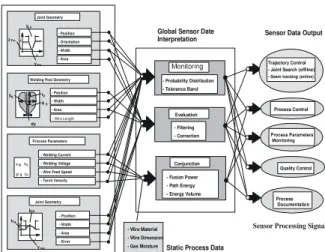
Besides the acquisition and parallel processing of information coming from very different sensors, another key point is the integra-tion of the informaintegra-tion (Drews & Willms, 1996). This data fusion concerns the consideration of all relevant aspects of a manufacturing process.
The information flow can be grouped in tree phases. These are: process monitoring data, validation of this information and the interrelation of variables to obtain process parameters and actuating signals. This is shown schematically in Figure 5.
Typical process parameters such as welding pool width, voltage, current, torch velocity etc., are combined using a process model to obtain a complete description of the welding state. The multi-sensor can deliver specific process information and global values concern-ing:
•Motion control based on local path tracking; •Process control and monitoring;
•Quality control.
Transputer X DSP's
The experience of implementing distributed processing systems on two distinct parallel platforms allows some interesting conclu-sions concerning the applicability of parallel digital architectures in the context of manufacturing process automation.
- Wire Material - Wire Dimension - Gas Moisture
- Probability Distribution - Tolerance Band
Evaluation - Filtering - Correction
Conjunction - Fusion Power - Path Energy - Energy Volume
x x x x x x xx xx x xx xx
z y
bF
Y zFm
Fm Joint Geometry
Welding Pool Geometry - Position - Width - Area
IS
v ;DvS
U ;S
Process Parameters - Welding Current - Welding Voltage - Wire Feed Speed - Torch Velocity
x x x xx x xx
x x
z
y
bN
hN
YNm Joint Geometry
- Position - Width - Area - Error - Position - Orientation - Width - Area
Global Sensor Date
Interpretation Sensor Data Output
Static Process Data
Trajectory Control - Joint Search (offline) - Seam tracking (online)
Process Control
Quality Control
Process Documentation dy
lD
bS
AS
Sensor Processing Signal
- Wire Length
Figure 5. Multi-sensor information flow.
Digital Signal Processors (DSP's) have greater computational speed, mainly due to a Wallace Tree Hardware implementation of the floating point multiplication unit (AT&T, 1989). The iNMOS T805 Transputer implements floating point multiplication using microcode (iNMOS, 1992), a technique to reduce costs. A great difficulty using the specialized DSP's in automation and control is that they were conceived to implement efficiently the internal prod-uct, the basic operation of digital processing. They do not have facilities in their hardware architecture or development environment to implement parallel or concurrent processing, because the provi-sion of resources for event handling could slow down the main processing. The implementation of a real-time Kernel to manage multiprocessing was not possible on the DSP32C from AT&T, due to the impossibility of saving certain CPU status bits (necessary to enable context switching). Only one interrupt level is implemented. Twenty 24 bit registers, four 32 bit floating point accumulators and status and control registers form a register set. Two such banks are available. To reduce interrupt latency these two register sets are swapped when entering the interrupt routine. There is no support to save registers automatically on the stack. Indeed, in most typical signal processing applications this is not necessary.
The adopted solution to use DSP number crunching capability in the implementation of the non-linear process control was to dedicate one DSP32C to the robot joint control and another DSP32C to trajectory planning and predictive servo-control. Both CPU's stay in waiting loops, waiting for interrupts that signal different events. The communication between the units was carried out on a dedicated DT-Connection 16 bit parallel interface.
On the other hand, Transputers have innate parallel processing facilities to help distributed tasks that would control the process in real time (using concurrent C-toolset, OCCAM etc.). Another ad-vantage is the great modularity of transputer systems, which enables easy reconfiguration of the transputer net topology. The concurrent software support permits a natural integration of individual sensors, making it easy to derive global process information.
Conclusion
By implementation of multi-sensor systems using distributed modules, it was shown that parallel processing architectures present considerable advantages when compared with standard bus-based systems. It is quite impossible to monitoring, at the same time, weld pool, welding parameters, vision system information and seam tracking using just standard bus. The welding system control need all the information, at once, coming from the weld run and the only way to process, all the multi-sensor information flow, is using paral-lel processing. (Transputer units or cluster system).
As described in this paper, it was possible to automate the whole metal welding process in MIG/MAG technology, using parallel processing units. The implemented distributed parallel processing system used 12 transputers in their most complete version. The main advantages of the proposed parallel approach lies in the scalability of computational processing capacity and capability for easy inte-gration of different sensor types due to a modular hardware plat-form. This approach is very interesting for industrial applications because a good price/performance relation can be achieved.
When high computational speed is needed, as in the calculation of non-linear control schemes, the signal processor is superior. An effective solution is to combine both architectures, i.e., algorithm-specialized DSP processors interconnected with process modules (sensors & actuators) using modular real-time supporting Transputer units.
Future Perspectives
The systems discussed in this work demonstrate how complex processes can adequately be controlled and monitored using distrib-uted intelligence. There is, however, a central instance, in the form of an information manager. The trend would be to avoid this central unit by the use of process-specific expert knowledge. This would avoid bottlenecks that appear in more sophisticated applications. A solution could be conceived in the form of co-operating autonomous units, which could be implemented using the concept of agents (Brooks & Connell, 1986).
Acknowledgments
This work was supported by the Deutsche Forschungs Gemein-schaft (DFG) and by a co-operation program of APS-Mechatronik/Aachen - GRACO/UnB sponsored by DAAD - Ger-many and CAPES/CNPq - Brazil.
References
Alexander, W.E.; Reeves, D.S.; Gloster Jr. C.S.: Parallel Im-age Processing with the Block Data Parallel Architecture. Pro-ceedings of the IEEE - Special Issue on Parallel Architecture for Image Processing, July 1996, Vol. 84, No7, pp 947-968
Alfaro, S.C.A.; Bauchspiess, A.; Casanova Alcalde, V.H.; van Els, R. H.; Soares Jr, L.R.; Suguieda, M.H., 1997: Conception and develop-ment of an integrated welding cell, 8th International Conference on the
Joining of Materials, JOM-8, Helsingor, Denmark, May 11-14, 1997 Bauchspiess, A., Alfaro, S. C. A.: Predictive sensor guided robots in welding cells, IEEEIRSJ 10th International Conference on Intelligent Robots and Systems - IROS'97, 7-11 Sept. 97, Grenoble - France
Bauchspiess, A.; Wagner, B.; Benker, P., 1997: Neural Network Pat-tern Recognition for Robust and Highly Precise TCP Trajectory Measur-ing for Industrial Robots, III CBRN - Congresso Brasileiro de Redes Neurais, July 21-24 1997, Florianopolis, SC/Brasil
Bauchspiess, A.: Pradiktive sensorgesteuerte Bahnfuhrung von Handhabungssystemen, Ph.D. Thesis, Universitat Erlangen-Niirnberg, 1995, in german
Brooks, R.A.; Connell, J.H.: Asynchronous Distributed Control Sys-tem for a Mobile Robot. Proc. SPIE 1986, Mobile Robots, 727.1986 pp. 77-84
Drews, P.; Trier, W.: Einsatz paralleler Sensordatenverarbeitung and einer Fuzzy Entscheidungsunterstiitzung, Parallele Datenverarbeitung mi dem Transputer, J. Hektor, R. Grebe (Hrsg.), Informatik aktuelle, Springer-Verlag 1994, pp 263 ff, in german
Drews, P. & Willms, K.: Multisensorsystem zur Erfassung der Pro-zel3umwelt beim SchutzgasschweiBen. Bander, Blache, Rohre 1/2, Februar 1996, pp 36-46, in german
Duelen, G.; Bernhardt, R.; Katschinski, V. & Ozdes, D.: Seam-Welds Inspection of Underwater Structures using Submersible Mobile Robot. In `Information Processing in Autonomous Mobile Robots' - Proceedings of the International Workshop, Springer-Verlag, pp. 311-329, March 6-8, 1991
Farber, F.; Helling, S.; RuB, A.: Architectural Features of Computer Systems for Autonomous Mobile Robot Applications. In `Information Processing in Autonomous Mobile Robots' - Proceedings of the Interna-tional Workshop, Springer-Verlag, March 6-8, 1991, pp. 247-263
Frohlich, C.; Freyberger, F.; Karl, G. & Schmidt, G.: Multisensor System for na Autonomous Robot Vehicle. In `Information Processing in Autonomous Mobile Robots' - Proceedings of the International Work-shop, Springer-Verlag, March 6-8, 1991, pp. 61-76
Fuchs, K.; Trier, W.: A Transputer Based Vision System for Indus-trial Robots, Proceedings 'Euromicro Workshop on Parallel and Distrib-uted Processing', Gran Canaria, January 27-29, 1993, pp. 369-374.
iNMOS / SGS-Thomson Microeletronics: The Transputer Databook, 1992
Krikelis, A.; Lea, R.M.: A Modular Massively Parallel Computing Approach to Image
Related Processing. Proceedings of the IEEE - Special Issue on Par-allel
Architecture for Image Processing, July 1996, Vol. 84, No7, pp 988-1004 Hwang, K.: Advanced Computer Architecture - Parallelism, Scal-ability, ProgrammScal-ability, McGraw-Hill, 1993
Kovacevic, R.; Zhang, Y.M.: Neurofuzzy Model-Based Weld Fusion State Estimation, IEEE Control Systems, Vol. 17, No. 2, April 1997, pp. 30-42
Kam, M.; Zhu, X., Kalata, P.: Sensor Fusion for Mobile Robot Navi-gation. Proceedings of the IEEE, Special Issue on Data Fusion, January 1997, Vol.85, No.1, pp. 108-119
Lim, S.Y.; Dawson, D.W.; Vedagarbha, P.: Advanced motion control of mechatronic systems via a high-speed DSP and a parallel processing transputer network, Mechatronics, Vol. 6, No 1, 1996, pp.101-122.
Starke, G.: "Nahtfiihrungssensor zur adaptiven Steuerung von Handhabungseinrichtungen zum Lichtbogenschweil3en", Ph.D. The-sis, RWTHAachen, 1983, in german
Strunz, U.: "Umgebungsmodellierung and sensorunterstiitzte Navi-gation fiir mobile Roboter", Ph.D. Thesis, RWTH-Aachen, 1993, in german