HAMED ALINEZHAD KORDI
METAL TRANSFER MAPPING FOR FCAW PROCESS
BY USING NEAR-INFRARED FILMING
FEDERAL UNIVERSITY OF UBERLANDIA
FACULTY OF MECHANICAL ENGINEERING
II
HAMED ALINEZHAD KORDI
METAL TRANSFER MAPPING FOR FCAW PROCESS BY USING
NEAR-INFRARED FILMING
Dissertation presented to the Postgraduate Program of Mechanical Engineering at Federal University of Uberlandia, as a part of requirements for obtaining the title of MASTER IN MECHANICAL ENGINEERING.
Concentration Area: Materials and Manufacturing Processes.
Supervisor: Prof. Dr. Louriel O. Vilarinho
Dados Internacionais de Catalogação na Publicação (CIP) Sistema de Bibliotecas da UFU, MG, Brasil.
A411m 2016
Alinezhad Kordi, Hamed, 1989-
Metal transfer mapping for FCAW process by using near-infrared filming / Hamed Alinezhad Kordi. - 2016.
87 f. : il.
Orientador: Louriel Oliveira Vilarinho.
Dissertação (mestrado) - Universidade Federal de Uberlândia, Programa de Pós-Graduação em Engenharia Mecânica.
Inclui bibliografia.
1. Engenharia mecânica - Teses. 2. Soldagem elétrica - Teses. I. Vilarinho, Louriel Oliveira, 1975-. II. Universidade Federal de Uberlândia. Programa de Pós-Graduação em Engenharia Mecânica. III. Título.
III
I dedicate my dissertation to my parents. A special feeling of gratitude to my lovely parents “Mehran and Manizheh”.
IV
ACKNOWLEDGEMENTS
There have been many people who have walked alongside me during the last
two years. They guided me, placed opportunities in front of me and showed me the
doors that might be useful to open.
Firstly, I would like to express my sincere gratitude to my advisor Prof. Louriel
Oliveira Vilarinho for the continuous support of my master study and related
research, for his patience, motivation, and immense knowledge. His guidance helped
me in all the time of research and writing of this dissertation. I could not have
imagined having a better advisor and mentor for my master study.
Besides my advisor, I would like to thank the Federal University of Uberlandia
(UFU) and the Faculty of Mechanical Engineering for opportunity to conduct this
course. Also to
“
CAPES
”
for the financial support in providing scholarship for
development this work.
And have to thank all the wonderful people in Brazil, family and friends of Iran,
our welding laboratory group (LAPRASOLDA), etc. who have helped me enormously.
Actually
I would never have been able to finish my dissertation without the guidance,
kindness and help of these peoples.
V
HAMED, A. K.
METAL TRANSFER MAPPING FOR FCAW PROCESS BY USING
NEAR-INFRARED FILMING.
2016. 87p. Master Dissertation, Federal University of
Uberlandia, MG, Brazil.
Abstract
In the Flux Cored Arc Welding (FCAW) process, the transfer of filler metal (metal
transfer modes) to the base material to accomplish the weld bead determines the
weld quality and therefore studies of such phenomena is demanded. Thus, in this
work, the metal transfer through the FCAW process is investigated by filming the
phenomena with the assist of near infrared visualization. During the literature survey,
it was found that this technic has not been used so far for analyzing the FCAW
process. It must be pointed out that the radiation emitted from the weld arc, fumes
and particles (spattering) in this process represent a barrier for these studies based
in the process visualization. The monitoring of metal transfer for FCAW process was
carried out within the operational envelope of voltage and wire feed speed with the
electrode E71T-1 (1.2 mm diameter) and Ar+25%CO
2as a shielding gas. A local
developed near infrared filming with frame rate of 300 Hz was employed for metal
transfer visualization in order to contribute to a better understanding of this process
and evaluating characteristics of metal transfer, unlike previous studies, which used
shadowgraph technique. It can clearly be seen how the droplet is created and
transferred in this process and also identify the different modes of metal transfer by
changing the parameters of voltage and wire feed speed in metal transfer maps. The
final result of this study is the metal transfer mode maps, which establish suitable
conditions and provide the basis for developing arc control strategies for the FCAW
process.
VI
HAMED, A. K.
MAPEAMENTO DA TRANSFERÊNCIA METÁLICA PARA
PROCESSO FCAW UTILIZANDO FILMAGEM POR INFRAVERMELHO PRÓXIMO.
2016. 87f. Dissertação de Mestrado, Universidade Federal de Uberlândia,
Uberlândia.
Resumo
No processo Eletrodo Tubular (Flux Cored Arc Welding
–
FCAW), a transferência do
metal de adição (transferência metálica) para o material de base, de forma a obter o
cordão de solda, determina a qualidade da solda e, portanto, estudos sobre este
fenômeno são demandados. Assim, neste trabalho, a transferência metálica durante
o processo FCAW é investigada filmando-se esse fenômeno com o auxílio de
visualização por infravermelho próximo. Durante a revisão da literatura, não se
encontrou outros trabalhos que utilizassem tal metodologia. Deve-se ressaltar que a
radiação emitida pelo arco, fumos e partículas (respingos) durante o processo
dificulta a visualização do processo. O monitoramento da transferência metálica do
processo FCAW foi realizado dentro do envelope de trabalho de tensão e velocidade
de alimentação do eletrodo E71T-1 (1,2 mm de diâmetro) e Ar+25%CO
2, como gás
de proteção. Foi utilizado um sistema de visualização por infravermelho próximo
desenvolvido localmente a uma taxa de 300 quadros por segundo, de forma a
contribuir para o entendimento do processo e avaliação das características da
transferência metálica, diferentemente de outros processos, os quais utilizaram a
técnica de perfilografia (shadowgrafia). Foi possível observar a formação e
transferência da gota durante o processo e identificar os diferentes modos de
transferência ao se variar os parâmetros de tensão e velocidade de alimentação nos
mapas de transferência. Os resultados finais do trabalho são os mapas de
transferência, os quais estabelecem condições adequadas e fundam as bases para
o desenvolvimento de estratégias de controle do arco para o processo FCAW.
VII
دماح
یدرک داژنیلع
.
نق
هش
یرادربملیف اب یردوپ ریز یراکشوج دنیارف رد زلف لاقتنا
قیرط زا
یاهوترپ
زمرق نودام
.کیدزن
2016
.
87
ص
.
مان نایاپ
آ ،ایدنلاربآ لاردف هاگشناد ،دشرا یسانشراک ه
.ایدنلارب
هدیکچ
رد
یراکشوج دنیآرف
وت
لاقتنا یاه تلاح( هدننکرپ زلف لاقتنا ،یردوپ
ای هرهم لیکشت یارب هیاپ زلف ای راک هعطق هب )زلف
.دنکیم اضاقت ار هدیدپ نیا دروم رد رتشیب تاعلاطم اتسار نیمه هب هک دشابیم شوج تیفیک هدننک نییعت شوج هدرگ
م یاهوترپ طسوت هدیدپ زا یرادرب ملیف اب یردوپوت یراکشوج دنیآرف رد زلف لاقتنا ،همان نایاپ نیا رد ساسا نیارب
نودا
تسا هتفرگ رارق یسررب دروم کیدزن زمرق
نیا هک تسا هدش صخشم هتشذگ تایبدا رورم و تاعلاطم هب هجوت اب .
سوق زا هدش عطاس شبات هک درک هراشا دیاب.تسا هدشن هدافتسا یردوپوت دنیآرف لیلحت و هیزجت یارب لاح هب ات کینکت
ی هدنهد ناشن دنیآرف نیا رد دوجوم تارذ و دود ،شوج
زلف لاقتنا رب تراظن .تسا مسجت دنور رد هعلاطم یارب عنام ک
ا صخشم یتایلمع یاه خرن اب همان نایاپ نیا رد یردوپوت یراکشوج دنیآرف رد
اب هیذغت تعرس و ژاتلو ز
دورتکلا
E71T-1
(
1.2
زا یطولخم و )رطق رتمیلیم
75
دصرد
و نوگرآ
25
نبرک دیسکا ید دصرد
زاگ ناونع هب
اجنا ظفاحم
.تسا هدش م
میرف خرن اب یلحم هتفای هعسوت کیدزن زمرق نودام یاهوترپ شیامن متسیس کی زا روظنم نیدب
300
رب زلف لاقتنا یبایزرا یاه یگژیو و دنیآرف نیا رتهب کرد هب کمک روظنم هب زلف لاقتنا رب تراظن یارب زتره
دش هتفرگ راک هب ،تسا هدوب یفارگوداش کینکت هک یلبق شور فلاخ
دش هداوخ هدید حوضو هب لامع ،ماجنا رس.تسا ه
هرطق هنوگچ هک
رییغت اب زلف لاقتنا فلتخم یاه تلاح نینیچمه و دریگیم ماجنا دنیارف نیا رد زلف لاقتنا و هدش داجیا
لتخم یاه تلاح هشقن همان نایاپ نیا ییاهن هجیتن.دوب دهاوخ صیخشت لباق دورتکلا هیذغت خرن و ژاتلو یاهرتماراپ
ف
دنیارف یکیرتکلا سوق لرتنک یاه یژتارتسا هعسوت یارب ییانبم هئارا و بسانم طیارش داجیا ثعاب هک تسا زلف لاقتنا
دوشیم یردوپوت یراکشوج
.
VIII
LIST OF FIGURES
Figure 2.1.1: Schematic view of the FCAW process [5] ... 5
Figure 2.1.2: Schematic view of the SS-FCAW process [7] ... 6
Figure 2.1.3: Schematic view of the GS-FCAW process [7] ... 7
Figure 2.2.1: The basic manufacturing Inner shield Electrodes steps [6] ... 9
Figure 2.2.2: Cored wire manufacturing process (Putting the flux in the cored wire) [7] ... 9
Figure 2.3.1: IIW classification of metal transfer depicted in an arc voltage and welding current diagram [12] ...12
Figure 2.3.2: Fundamental transfer modes. U (I) diagram based on the classification [9] ...13
Figure 2.3.3: Image sequence captured during metal transfer of a rutile wire for a current around 160A. (a) Welding with 100% CO2 (b) Welding with 75% Ar-25% CO2 [2] ...15
Figure 2.3.4: Image sequence captured during metal transfer of a rutile wire for a current around 200 A. (a) Welding with 100% CO2 (b) Welding with 75% Ar-25% CO2 [2] ...16
Figure 2.3.5: Metal transfer map for welding with shielding gas containing Ar+2% O2 [3] ...17
Figure 2.3.6: Metal transfer map for welding with shielding gas containing Ar+5% O2 [3] ...17
Figure 2.4.1: visualization of metal transfer by shadowgraph technique [18] ...18
Figure 2.4.2: visualization of molten metal by indirect illumination [19] ...19
Figure 2.4.3: Images obtained with filter at 950 nm in the study of the MIG/MAG process [21]...19
Figure 2.4.4: Principle of spectrum filtering [19] ...20
Figure 2.4.5: Set the exposure time of the camera to minimize the power applied to the pulsed laser compared to the continuous nature of the arc radiation [4] ...20
Figure 2.4.6: Viewing system with high-power laser diodes in near infrared for TIG (left) and MIG/MAG welding (center and right) [17, 4] ...21
Figure 3.1.1: Welding power supply (IMC MTE Digitec 300) ...24
Figure 3.1.2: Electrode wire feeding system (IMC STA-20) ...25
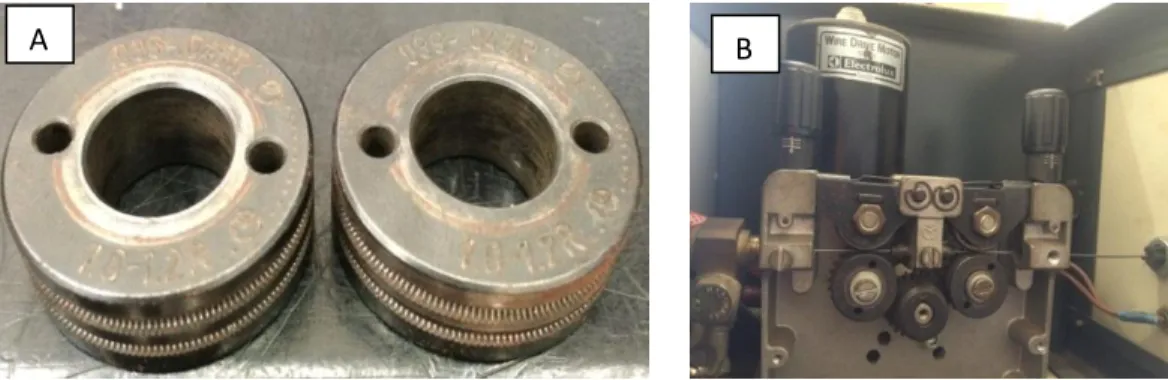
Figure 3.1.3: A) Knurled V groove rolls for FCAW B) The 4 rollers set up wire feeder ...26
Figure 3.1.4: Welding torch, steel contact tip and shielding nozzle ...27
Figure 3.1.5: Welding table ...27
Figure 3.1.6: A) Signal Conditioner; B) Acquisition board; C) Hall Effect sensor; D) LabVIEW programming software; E) OriginPro 9.0 application. ...29
Figure 3.1.7: Clamping system for supporting of plate during the welding process. ...29
Figure 3.1.8: Source of Infrared (ViaSolda) ...30
IX
Figure 3.1.10: HiSpec 5 home Screen Software...31
Figure 3.2.1: A) Flowmeter, B) regulator...33
Figure 3.2.2: FCAW Electrode Classification (AWS Specification- A5.20) ...34
Figure 3.2.3: A) horizontal bandsaw machine B) surface grinder machine ...37
Figure 3.3.1: A diagram showing the contact tip position relative to the shielding nozzle used during welding ...38
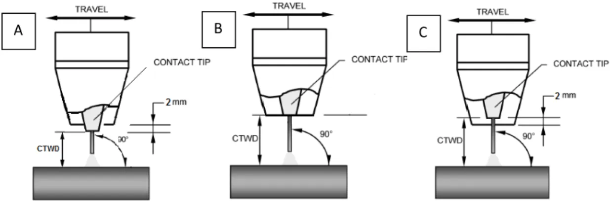
Figure 3.3.2: Travel angle. A) Forehand, B) Perpendicular, and C) Backhand angles [4] ...39
Figure 3.3.3: work angle [27] ...39
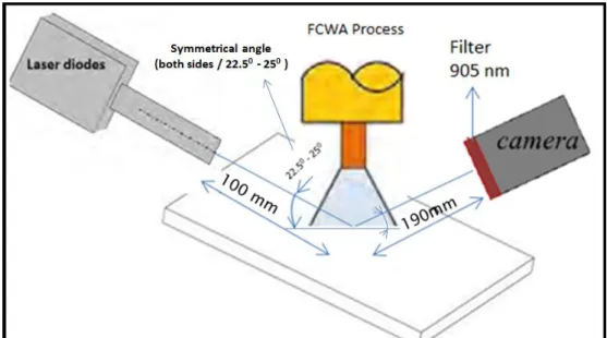
Figure 3.3.4: Schematic of 3-dimensional imagery technic positioning ...42
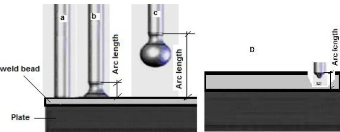
Figure 3.3.5: Observation of different arc lengths...43
Figure 3.3.6: Schematic view to measuring of arc length in different situation ...44
Figure 4.1: Observed and categorized metal-transfer modes during FCAW ...47
Figure 4.1.1: Voltage and current signals for a short circuit metal transfer-(Run 39) ...50
Figure 4.1.2: Image sequence captured during FCAW in a short circuit transfer mode- (Run 39) ...51
Figure 4.1.3: Voltage and current signals for a short circuit and free flight metal transfer-(Run 28) ...52
Figure 4.1.4: Schematic electrode positioning for A) without buried and B) with buried metal transfer type ...53
Figure 4.1.5: Image sequence captured during FCAW in a short circuit and free flight mode without buried (SC-FF-WOB)-(Run 48) ...54
Figure 4.1.6: Image sequence captured during FCAW in a short circuit and free flight mode with buried (SC-FF-WB)-(Run 71) ...56
Figure 4.1.7: Voltage and current signals for a free flight metal transfer-(Run 55) ...57
Figure 4.1.8: Schematic of metal transfer for A) Split type and B) Conjunct ...58
Figure 4.1.9: Image sequence captured during FCAW in a free flight mode without buried in conjunct type (FF-WOB-CO)-(Run 46) ...59
Figure 4.1.10: Image sequence captured during FCAW in a free flight mode without buried in split type (FF-WOB-SPL)-(Run 102)...61
Figure 4.1.11: Image sequence captured during FCAW in a free flight mode with buried (FF-WB) A) Run 88 B) Run 79 ...62
Figure 4.2.1: Map of metal transfer modes in FCAW process as a function of mean welding voltage and wire feed speed...64
Figure 4.2.2: Map of metal transfer modes in FCAW process as a function of mean arc length and mean current ...64
X
XI
LIST OF TABLES
Table 2.1: Summary of metal transfer mode evolution [13] ...11
Table 2.2: Proposed classification of metal transfer in GMA processes [9] ...14
Table 2.3: Characteristics of LED diodes and laser diodes [16] ...21
Table 2.4: Characteristics of the SPL PL90_3 pulsed laser diode [22]...22
Table 3.1: Nominal chemical composition of AISI 1020 steel ...35
Table 3.2: Welding parameters to find plate thickness ...36
Table 3.3: Experimental design showing the test numbering (from 1 to 108) ...40
Table 4.1: Applicable and non-applicable tests number (input values to power source) ...48
Table 4.2: Set value and monitoring results for short circuit mode ...49
Table 4.3: Set value and monitoring results for short circuit and free flight without buried (SC-FF-WOB) ...53
Table 4.4: Set value and monitoring results for short circuit and free flight with buried (SC-FF-WB) ..55
Table 4.5: Set value and monitoring results for free flight metal transfer without buried in conjunct type (FF-WOB-CO)...59
Table 4.6: Set value and monitoring results for free flight metal transfer without buried in split type (FF-WOB-SPL)...60
XII
LIST OF SYMBOLS
AWS - American Welding Society
GMAW - Gas Metal Arc Welding
FCAW - Flux Cored Arc Welding
MIG - Metal Inert Gas
MAG - Metal Active Gas
GS-FCAW - Gas Shielded Flux Cored Arc Welding SS-FCAW - Self Shielded Flux Cored Arc Welding
SAW - Submerged Arc Welding
TIG - Tungsten Inert Gas
……….
AC - Alternating Current
DC - Direct Current
DCEP - Direct Current Electrode Positive
DCEN - Direct Current Electrode Negative
I - Current
Im - Mean Current
Irms - Effective Current
U - Voltage
Um - Mean Voltage
Urms - Effective Voltage
Ur - Reference Voltage
……….
CTWD - Contact Tip to Work Distance
ESO - Electrical Stick Out
La - Arc Length
MR - Melting Rate
……….
CO - Conjunct
RE
FF
- Repulsion
- Free Flight
SC - Short Circuit
SP - Spray
SPE - Spray elongation
SPL - Split
WB - With Buried
WOB - With Out Buried
……….
ABNT - Brazilian Association of Technical Standards AISI - American Iron and Steel Institute
DAQ - Data transient Acquisition system
IPM - Inches per Minute
NIR - Nera Infrared
……….
h - Plate thickness (mm)
hcrit - The critical thickness (mm)
H - Welding energy (kj/mm)
HL - Heat input (kj/mm)
Ws - Welding Speed (cm/min)
WFS - Wire Feed Speed (m/min)
C - Specific heat of the base material (j/g 0C) T0 - Initial temperature or preheating (0C)
Tp - Peak temperature (0C)
Tf - Melting temperature of base metal (0C)
Ʈ - Relative thickness
ρ - Density of base material (g/cm3)
XIV
Table of contents
Abstract ... V Resumo... VI
کچ ی
هد ... VII LIST OF FIGURES... VIII LIST OF TABLES ... XI LIST OF SYMBOLS ... XII
CHAPTER I ... 1
INTRODUCTION ... 1
CHAPTER II ... 4
LITERATURE REVIEW ... 4
2.1 Fundamentals of Flux Cored Arc Welding process (FCAW): ... 4
2.2 Manufacturing Inner shield Electrodes: ... 8
2.3 Definition of metal transfer modes ... 9
2.4 Vision System in Welding...17
CHAPTER III ...23
EXPRIMENTAL EQUIPMENT, MATERIALS AND METHODS ...23
3.1 Experimental Equipment ...23
3.1.1 Welding power supply: ...24
3.1.2 Electrode wire feeding system: ...25
3.1.3 Welding torch: ...26
3.1.4 Coordinate welding table: ...27
3.1.5 Electrical data transient Acquisition system (DAQ): ...28
3.1.6 Holding system for plates: ...29
3.1.7 Digital High Speed Camera and Near-infrared vision system: ...30
3.2 Material and Consumable...32
3.2.1 The shielding gas: ...32
3.2.2 Filler metal or electrode: ...33
3.2.3 Metal base and workpiece: ...34
3.3 Methodology ...38
3.3.1 Contact Tip to Work Distance (CTWD)...38
XV
3.3.3 Voltage, Wire Feed Speed and Travel speed,...40
3.3.4 Position of systems form interest area ...41
3.3.5 Measurement of the arc length ...42
3.3.6 Turning on the ViaSolda ...44
3.3.7 Drawing the metal transfer maps...44
3.3.8 Preparation of welding environment ...44
3.3.9 Welding Experimental Procedure...45
CHAPTER IV ...46
RESULTS AND DISCUSSION ...46
4.1 Metal transfer modes ...46
4.1.1: Short Circuit (SC): ...48
4.1.2 Short circuit and free flight (transition area): ...51
4.1.2.1 Short circuit and free flight without buried (SC-FF-WOB): ...53
4.1.2.2 Short circuit and free flight with buried (SC-FF-WB): ...54
4.1.3 Free Flight: ...56
4.1.3.1 Free flight without buried in conjunct type (FF-WOB-CO) ...58
4.1.3.2 Free flight without buried in split type (FF-WOB-SPL) ...60
4.1.3.3 Free flight with buried (FF-WB) ...61
4.2 Presentation of metal transfer maps ...63
CHAPTER V ...66
Conclusion ...66
CHAPTER VI ...68
Improvements – Future Work ...68
CHAPTER VII ...70
CHAPTER I
INTRODUCTION
Gas Metal Arc Welding (GMAW) process has been in use since the early 1920's. Experiments at that time showed a significant improvement of weld metal properties when the arc and molten weld metal were protected from atmospheric contamination. However, the development of coated electrodes in the late 1920's reduced the interest in gas shielded methods.
Not until the early 1940's, with the introduction of the commercially-accepted gas tungsten arc welding process, it did there become a renewed interest in these gas-shielded methods. Later in that same decade, the gas metal arc welding process was successfully commercialized. Argon and helium were the two primary shielding gases at that time.
Research work conducted on manual coated electrode welds dealt with an analysis of the gas produced in the disintegration of electrode coatings. Results of this analysis showed that the predominant gas given off by electrode coatings was CO2. This discovery led quickly to the use of CO2 for shielding of the gas metal arc process when used on carbon steels. Although early experiments with CO2 as a shielding gas were unsuccessful, techniques were finally developed which permitted its use. Carbon dioxide shielded GMAW became commercially available in the mid-1950's.
2
Flux cored arc welding (FCAW) process was introduced publicly at the AWS Exposition held at Buffalo, New York, in May 1954. The electrodes and equipment were refined and introduced in essentially the present form in 1957. The process is being continually improved. Power sources and wire feeders are now greatly simplified and more dependable than their predecessors. The new guns are lightweight and rugged. Electrodes are undergoing continuous improvement. Alloy electrodes and small diameter electrodes down to 0.035 in. (0.9 mm) are some of the later advances [1].
The FCAW process is currently one of the most widely used arc welding process in industry. Benefits such as high production rates, high weld quality, ease of automation, and the ability to weld many metals make it attractive to manufacturers. One of the unique characteristics in this process is the way molten metal is transferred across the arc. The transfer of metal from the electrode to the workpiece influences penetration, bead morphology, fume generation, process stability, and spatter. Metal transfer is controlled by several parameters, including current, voltage, polarity, electrode extension shielding gas composition, and electrode diameter.
3
the radiation of welding arc by using near infrared filming. Also the direct visualization in this study has ability to monitor the weld pool. It takes advantage of the specular surface of a molten weld pool by reflecting of lights from the weld pool surface. Also the electrical signals through the arc is one sensing strategy for an intelligent welding control system which monitored in this study. A local developed near infrared filming with frame rate of 300 Hz was employed by Mota [4] for metal transfer visualization in order to contribute to a better understanding of this process and evaluating characteristics of metal transfer, unlike previous studies, which used shadowgraph technique.
4
CHAPTER II
LITERATURE REVIEW
This chapter provides an overview of previous research on knowledge sharing and intranets. It introduces the framework for the case study that comprises the main focus of the research described in this dissertation.
This literature review aims to gather information about the welding process of Flux Cored Arc Welding (FCAW), mode of metal transfer on that, vision system in welding and serve as a technical and scientific basis to understand the basic principles involved in that process, the basis for discussion of results.
2.1 Fundamentals of Flux Cored Arc Welding process (FCAW):
Flux Cored Arc Welding is an arc welding process that uses an arc between a continuous filler metal electrode and the weld pool. The process is used with shielding from a flux contained within the tubular electrode, with or without additional shielding from an externally supplied gas, and without the application of pressure (Figure 2.1.1).
5
Figure 2.1.1: Schematic view of the FCAW process [5]
A fundamental principle of arc welding is that the arc and molten weld metal must be protected from exposure to the atmosphere. Otherwise nitrogen and oxygen (approximately
99% of air’s constituents) will react with the arc and will be absorbed into the molten metal.
Before the puddle solidifies, the absorbed gases may not completely escape. The result is porosity in the weld metal and typically a significant decrease in the weld’s mechanical
properties, particularly toughness [6].
6
and resulting operator appeal (less spatter, smoother arc, etc.). However, these processes are very sensitive to arc interference and contamination from surrounding air flow [6].
The Flux-Cored Arc Welding (FCAW) process uses a continuously fed electrode to supply filler metal to the arc. The electrode is not solid, but rather is tubular with flux inside of it. This process is then divided into two fundamentally different sub-processes; the Self-Shielded Flux-Cored Arc Welding (SS-FCAW) process and the Gas-Self-Shielded Flux-Cored Arc Welding (GS-FCAW) process. While electrodes for both sub processes produce a slag covering over the weld, the method in which they protect the arc from the surrounding atmosphere is quite different. With the SS-FCAW process, reactionary agents necessary to shield the arc and cleanse the molten weld pool are placed inside the tube. No additional shielding is required (Figure 2.1.2). Whereas the GS-FCAW process has a different type of flux core system and relies completely on an external shielding gas for atmospheric protection (Figure 2.1.3).
7
Figure 2.1.3: Schematic view of the GS-FCAW process [7]
Like any process, welding with tubular electrode has its advantages and limitations. For your application, it must be analyzed, along with the practical results, to see, it becomes convenient or not. The benefits of FCAW process are related to its:
• Productivity related to the use of continuous wires;
• Metallurgical benefits from the internal wire flow:
• Aid the slag in the form and appearance of the weld bead.
• High quality of the deposited metal;
• Excellent weld appearance (uniform solder);
• Welding various types of steel and in large thickness ranges;
• Easy operation due to the high ease of mechanization;
• High deposition rate due to high current density;
• Relatively high efficiency of deposition;
• Requires less cleaning than in GMAW (More deoxidizer within the flux);
• High tolerance for contaminants that can cause cracks;
8
On the other hand, the process limitations are related to:
• Limited to weld ferrous and alloy nickel-based;
• Slag removal need;
• The equipment is more expensive compared to that used for the SMAW welding process;
• Outdoor welding Restriction (only for FCAW welding with shielding gas);
• The wire feeder and the power source must be close to the workplace;
• It generates more fumes than the GMAW and SAW processes.
2.2 Manufacturing Inner shield Electrodes:
The process of drawing down and adding flux to the inside of an electrode is much more complex than drawing down solid electrodes (i.e. MIG wire). Flux-cored electrodes are
considered “fabricated” wires. The basic manufacturing steps include:
1. Flux-cored electrodes start off in one of two forms of raw steel, round “green rod” or flat “strip”.
2. The steel is drawn down and rolled into a “U” shape.
3. Flux ingredients are then uniformly poured into the U shaped tube. Monitoring equipment ensures that 100% of the electrode has the proper fill rate.
4. The electrode is then rolled together with a tight seam, which is either a butt or lap
seam. The outer steel tube is called the “sheath” or “jacket” and the inner portion is the “flux core”.
5. The electrode is then drawn down to its final diameter and a lubricant is applied to the surface. This lubricant, aids in wire feeding and acts as a rust inhibitor. Cored electrodes are not copper coated1 like solid electrodes (i.e. TIG, MIG or submerged arc electrodes), in which the copper is attached via an acid bath and chemical reaction. If it were attempted with cored electrodes, the acid solution would seep through the seam and contaminate the flux [6].
1
9
.
Figure 2.2.1: The basic manufacturing Inner shield Electrodes steps [6]
Figure 2.2.2: Cored wire manufacturing process (Putting the flux in the cored wire) [7]
2.3 Definition of metal transfer modes
10
The mode of metal transfer is determined by many other factors:
Base Metal Type; Filler Metal Composition; Electrode Diameter; Polarity;
Arc Current;
Arc Voltage/Arc Length; Shielding Gas Composition; Welding Position;
CTWD (contact tip to work distance)
In metal transfer, if the wire feed rate be balanced by its fusion rate, the process wrought of stable shape and keeps going. A failure in this swing resulted in the arc extinction, or short circuit or excessive growth of the arc. The relationship between the rate of melting and the current is given and widely presented in the literatures as:
Equation 2-1
Where MR is melting rate, α and β are constants associated with the gas protection, polarity and diameter and material of electrode, I is current and L is the electrode extension.
Following the first classification of arc types in 1976 [8], several further classifications have been proposed. Short circuit, globular, and spray are the three major classifications of metal transfer types by the American Welding Society (AWS) [9]. The International Institute of Welding (IIW), in 1984, divided spray types into the three categories: (i) drop spray or projected spray, (ii) rotating spray, and (iii) streaming spray [10]. Norrish [11] and then Ponomarev et al [12] modified this categorization. Utilization of digital control of power sources has led to many improvements in arc control, especially in welding with short circuit and pulsed mode of metal transfer. Digital control increases the reaction speed of the power source inverter and the use of sophisticated software makes it possible to directly influence the arc [9]. Table 2.1 summarizes the attempt to classify metal transfer [13].
2 rms
m
LI
11
Table 2.1: Summary of metal transfer mode evolution [13]
Classification basis Description References
Droplet transfer Free flight, short circuiting. A slag mode is defined for other
arc welding (SAW)
IIW (1976), referred by Lancaster (1984) as Anon Droplet transfer and
droplet size
Categorization by level of current and drop size current: moderate current (globular), relatively high current (spray), high current (stream), very high current (rotating)
Lancaster (1984)
Associated transfer mechanism
Mechanisms: (1) natural metal transfer, (2) controlled transfer techniques, and (3) extended operating mode techniques
Norrish (2003)
Transfer mechanism and labelled with alphabet letters
Suggested confining the classification to natural and controlled transfer modes. In addition, these authors proposed an extra fixed alphabetic label for each
‘fundamental’ metal transfer mode (A, short circuiting; B, globular; C, pulsed; D, spray; and E, rotating)
Lucas et al. (2005)
Current range, sketch illustration, and type of consumable electrode
Droplet transfer during GMA welding with solid wire and FCW has been observed in detail and the transfer
Izutani et al. (2006)
Sketch illustration of the mechanisms
and an alphabetic associated with number classification
The range of current is provided for each transfer mode A, short circuiting; B, globular; C, spray. Similar
approach using alphanumeric Labels (A, B1, B2, C1, C2, and C3). The controlled processes classification and defined two types of controlling processes, either simple controlled processes or real-time controlled processes
Iordachescu and Quintino (2008) Metal transfer-natural transfer, controlled transfer and mixed mode transfer, oriented to scientific personnel
Metal transfers are illustrated by a sequence of droplet transfer. Corresponding main forces governing the metal transfer are indicated for each case.
Metal transfer modes are categorized in a flow chart: natural transfer, controlled, and interchangeable transfer
12
According to Wang et al [14] arc modes are related to arc voltage and the level of current. By changing these two parameters, the modes of the arc can be changed. With small current, the droplet does not form until it touches the weld pool; this mode of arc is a so-called short circuit. The metal transfer mode changes to a globular when the current is increased so that a small electromagnetic force is generated. In a globular mode, the diameter of the droplet is bigger than the electrode and the droplet is formed by the gravitational force. By further increasing the current, the type of transfer changes to a projected spray mode, then a streaming mode, and finally a rotating mode. The different types of metal transfer can be shown in diagrams of arc voltage and current.
As an illustration of the influence of current, voltage, and shielding gas composition, Iordachescu and Quintino in an IIW meeting in 2003 classified arc types on the basis of
‘natural transfer modes’. Today, however, due to the use of more developed controllers,
natural transfer modes are no longer used as often [9]. Figure 2.3.1 from Ponomarev's study shows metal transfer types as a function of current, voltage, and shielding gas.
The transition current has been an important topic in the type of metal transfer in GMA welding. It sets the limit between globular and spray mode and determines the working conditions of the welding process, as suggested by Ponomarev [12] (Figure 2.3.1). According to Iordachescu and Quintino [9] there could be a second transition current between short circuit and globular, as illustrated in Figure 2.3.2. The aim of the suggestion is to cover both normal spray and projected spray.
13
In addition to a second transition current line, the study by Iordachescu and Quintino [9] suggested a new transfer mode classification of the arc in GMAW as a function of the current, voltage, and shielding gas: short circuiting, globular drop, globular repelled, drop spray, streaming, and rotating transfer modes. Figure 2.3.2 illustrates this classification of arcs in GMAW. The first transition current separates the globular with axial droplets and globular with repelled droplets and the second transition current separates the spray and globular fundamental group areas. In addition, the mode of arc changes with increasing welding current and arc voltage. The figure shows that the electric current in short arc transfer is lower than in other types of arcs and that rotating transfer needs a high current.
Figure 2.3.2: Fundamental transfer modes. U (I) diagram based on the classification [9]
A metal transfer mode classification structured on the increase of the current and voltage would be welcomed by most of the people active in the field, as it would allow to clearly understanding the relation between the process parameters and metal transfer modes, which are related with arc stability, bead appearance and bead quality.
14
A. Short circuiting—key-role played by the surface tension resultant force.
B. Globular—key-role played by the gravity resultant force.
C. Spray—key-role played by the arc pressure resultant force.
To make the proposed classification simpler, only the level two categories where denominated as fundamental transfer modes, as shown in Table 2.2. This makes the classification simpler, without losing the logic of numbering, both from fundamental point of view (the physics of the transfer) and the technological one (the increasing of the values of the welding parameters). Consequently, the six fundamental transfer modes in the new classification are: A-Short circuiting, B1- Globular drop, B2-Globular repelled, C1-Drop spray, C2-Streaming and C3-Rotating.
Table 2.2: Proposed classification of metal transfer in GMA processes [9]
Proposed denomination (fundamental modes) Proposed name (fundamental modes)
Sketch Comment Correspondent in IIW
classification [5]
A Short
circuiting
2.Bridging transfer 2.1Short circuiting
B1 Globular
Drop
1. Free flight transfer 1.1 Globular
1.1.1 Drop
B2 Globular
Repelled
CO2 GMAW
1. Free flight transfer 1.1 Globular
1.1.2 Repelled
C1 Drop Spray (projected) 1. Free flight transfer
1.2 Spray
1.2.1 Projected or not applicable, as presented by [8]
C2 Streaming 1. Free flight transfer
1.2 Spray 1.2.2 Streaming
C3 Rotating 1. Free flight transfer
15
In FCAW process, form of metal transfer depends primarily on the characteristics of each type of wire flux. According to Norrish [15], for rutile flux-cored wires, these consumables are normally operated in the spray mode where they give smooth non axial transfer. Some of the flux melts to form a slag layer on the on the surface of the droplet, a small amount decomposes to form shielding gases whilst some unmelted flux is transferred to the weld pool where it melts and produces a protective slag blanket. The unmelted flux projects from the tip of wire.
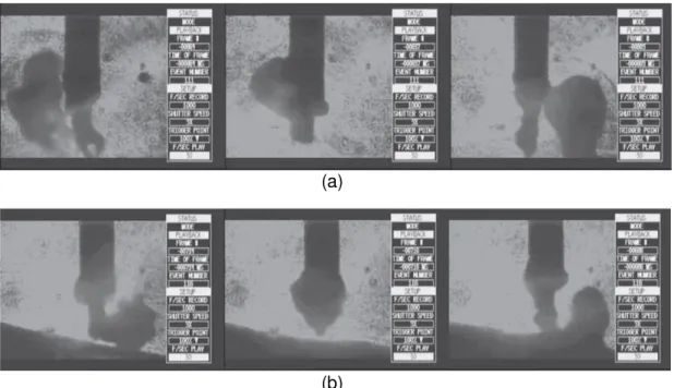
Cícero et al [2] evaluated the metal transfer in tubular wire welding by using a high
speed video camera and laser shadowgraphy. Welding tests with different current levels were performed with a rutile tubular wire of 1.2mm diameter, two gas mixtures (100%CO2 and 75%Ar-25%CO2) with an electrode stick out of 16mm and an arc length of 3.5mm. Globular metal transfer together with a flux column projecting towards the weld pool was observed for welding current around 160 A for both gas mixtures. A similar result was obtained for higher current levels (around 200 A), however with smaller drop diameter and higher transfer frequency. This effect was more pronounced for the welding trials with 75%Ar-25%CO2 shielding.
(a)
(b)
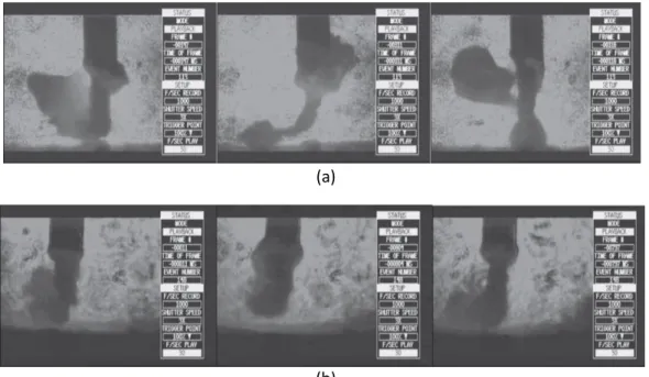
16 (a)
(b)
Figure 2.3.4: Image sequence captured during metal transfer of a rutile wire for a current around 200 A. (a) Welding with 100% CO2 (b) Welding with 75% Ar-25% CO2 [2]
In 2004, Luz et al [3] used one multi process welding source in the constant voltage mode and positive polarity (DC +) to analyzing the metal transfer of FCAW. The aim of this work was to obtain the metal transfer map of a commercial tubular wire (metal cored wire 409Ti) with a diameter of 1.2 mm and assess the shielding gas influence (Ar+2%O2 and Ar+5%O2) on the metal transfer. The contact tip to work distance (CTWD)was maintained at 18 mm, with torch perpendicular to the plate. A high-speed filming system was employed in addition to a laser head and a set of optical filters to provide the image recording of the electrode, droplets and bead shadows (this experimental rig is known as Shadowgraph or Backlight technique).
17
mode (mode pure) acts more strongly. In Region 1 there is the predominance of the globular way, region 2 the short circuit mode region 3 spray mode and the region 4 is spray mode with elongation. Finally, this study makes it clear that metal cored is similar to MIG/MAG.
Figure 2.3.5: Metal transfer map for welding with shielding gas containing Ar+2% O2 [3]
Figure 2.3.6: Metal transfer map for welding with shielding gas containing Ar+5% O2 [3]
2.4 Vision System in Welding
18
Currently, viewing systems are widely applied to aid studies of welding processed. The use of low- or high-speed cameras can provide different information that is useful to researchers, which is not possible to obtain with the usual monitoring of electrical signals such as current or voltage.
Despite the large current application, the idea of using a vision system is already disseminated from earlier times to digital photography. The first known work in this area [16, 4] was used a compound of an analog TV camera system and a TV monitor and projecting light through optical fibers to the application of a tracking system of the welding joint. Even at that time, was explored for the first time the idea of light in a specific spectrum (0.63μm) image acquisition with an interference filter ("bandpass") improving image contrast and decreasing light arc stemmed [17, 4].
Different viewing systems can provide specific information about the process in progress: the technique of backlighting (shadowgraph), i.e. projecting a shadow of elements in the weld area onto a flat surface as shown in Figure 2.4.1, permits visualization of drops in transfer as one way to study the metal transfer [18],
Whilst new viewing systems (figure 2.4.2) aim for direct visualization of the molten metal and the joint itself, with a range of applications ranging from study of the phenomena in the weld pool to joint tracking or online control of process parameters [4].
19
Figure 2.4.2: visualization of molten metal by indirect illumination [19]
Several studies were performed to obtain direct images of the weld pool, minimizing the light coming from the arc using interference filters ("bandpass") at different wavelengths. Some of the early work for direct viewing of the pool [20] used optical filters is around 950 nm for the study of the effect of protection and wire gas for MIG welding (Figure 2.4.3) and the study of the behavior of TIG welding puddle [4].
Figure 2.4.3: Images obtained with filter at 950 nm in the study of the MIG/MAG process [21]
20
Figure 2.4.4: Principle of spectrum filtering [19]
The camera shutter time also influences the amount of light during acquisition of the image. Thus, it is possible to reduce the luminous intensity of the arc by decreasing the exposure time of each frame captured. Pulsing the laser within each exposure time makes it so that a minimum power is necessary for the laser light to overlap with radiation from the arc, as the laser pulse is within the exposure time of the camera per every frame acquired, as can be seen in Figure 2.4.5 [4].
Figure 2.4.5: Set the exposure time of the camera to minimize the power applied to the pulsed laser compared to the continuous nature of the arc radiation [4]
21
Table 2.3: Characteristics of LED diodes and laser diodes [16]
Recent studies show the applicability of using high power laser diodes in the near infrared for vision systems of welding process. The light intensity emitted by the welding arc at infrared wavelengths above 850 nm is small compared to the visible spectrum. Figure 2.4.6 illustrates results obtained from this type of illumination technique [17, 4].
Figure 2.4.6: Viewing system with high-power laser diodes in near infrared for TIG (left) and MIG/MAG welding (center and right) [17, 4]
22
cameras are product specific and therefore costly, yet ordinary cameras have a wide range of models at low prices and with high flexibility [22].
Knowing that the base component for the light source should be a high-power laser diode with emission in the NIR spectrum, and because there are few commercially available semiconductors for performing the classification, this study used the Osram model SPL PL90_3 pulsed laser diode, with the highest power available and greater applicability in this study. Table 1 lists the main characteristics of this laser diode, according to the manufacturer database.
It should be noted that the semiconductor selected is a pulsed laser diode; that is, the component supports only certain pulses of current passing through the joint at a certain time interval, and not the continuous flow of current. Specifically for this model, it is important to note that the laser diode has a very low duty cycle of 0.1%, maximum pulse width of 100 ns, and maximum peak current of 40 A [22].
23
CHAPTER III
EXPRIMENTAL EQUIPMENT, MATERIALS AND METHODS
This chapter describes the equipment which used during the welding process, Also consumption of materials that used, are described with their respective specifications, equipment and accessories, as well as general assembly of experiments for conducting all tests needed. In addition, this chapter provides a description of the methodology that was used for completion of the proposed tests, as well as the selection parameters which aiming results quantitative and comparable.
3.1 Experimental Equipment
The main employed experimental equipment were:
Welding power supply;
Electrode wire feeding system; Welding torch;
Coordinate welding table;
Electrical data transient acquisition system (DAQ); Holding system for plates;
24 3.1.1 Welding power supply:
The power source provides electrical energy for the welding arc. For carrying out the welding tests, it used a multi process power supply. This welding power supply (IMC MTE Digitec 300) can be used for many processes such as SMAW, MIG/MAG, TIG and FCAW (Figure 3.1.1). It has a system of command with one keyboards and liquid crystal display, where the selection is made of processes and adjusting variables.
Figure 3.1.1: Welding power supply (IMC MTE Digitec 300)
Commercial arc welding power supplies are typically classified to operate in one of two modes: constant current or constant voltage. The power sources generally recommended for flux-cored arc welding are direct current constant voltage type. Direct current can be either reverse or straight polarity. Flux-cored electrode wires are designed to operate on either DCEP or DCEN. The wires with an external gas shielding system are generally designed for use with DCEP. Some self-shielding flux-cored ties are used with DCEP while others are developed for use with DCEN. Electrode positive current gives better penetration into the weld joint. Electrode negative current gives lighter penetration and it is used for welding thinner metal or metals where there is poor fit-up.
25 3.1.2 Electrode wire feeding system:
The wire feed speed regulates how much or how fast the wire is feed into the weld joint that measured in inches per minute (in/min - IPM) or meters per minute (m/min). Welding current (measured in amps) and resulting penetration levels are directly related to wire feed speed rates.A wire feed motor provides power for driving the electrode through the cable and gun to the work.
There is several different wire feeding systems available. In this case, it was used; the wire feeder "IMC STA-20" which it has electrode wire feed speed between 2.0 to 20.0 m/min (calibration equation: WFSreal=1.0274 WFSadjust) and also admits electrode wire diameters in the range 0.60 to 1.60 mm (Figure 3.1.2).
Figure 3.1.2: Electrode wire feeding system (IMC STA-20)
One of some different between the MIG/MAG process and Tubular electrode process is the type of rollers. As illustrated by Figure 3.1.3, during FCAW welding, it is used knurled V- or U-groove drive rolls in the wire feeder. Compared to a GMAW solid welding wire (which uses a smooth V-groove drive roll), FCAW wire is much softer (due to its tubular design) and if it utilized the incorrect drive roll, it can easily compress the wire. Cored electrodes also require the use of knurled drive rolls. A cored electrode cannot withstand as much drive roll tension or squeezing force as a solid electrode can with smooth drive rolls. The electrode would be crushed or deformed. The drive roll’s knurls (i.e. teeth) help grip the cored electrode, providing equivalent pushing force, but with less drive roll tension.
26
tension, begin by releasing the tension on the drive rolls. Increase the tension while feeding the wire into the palm of your welding glove and continue to increase the tension one half turn past wire slippage. If you tighten up the rollers too much, the wire will get crushed and then you will need to refeed the wire.
A wire feeder consists of an electrical motor connected to a gear box containing drive rolls. Inside the wire feed section of each GMAW or FCAW machine there will be a 2 drives or 4 drives roller set up. The four rollers set up provide a more constant feed capable of pushing the wire over a further distance.
Figure 3.1.3: A) Knurled V groove rolls for FCAW B) The 4 rollers set up wire feeder
3.1.3 Welding torch:
A welding torch is used in an automatic welding system to direct the welding electrode into the arc, to conduct welding power to the electrode, and to provide shielding of the arc area. There are many types of welding torches, and the choice depends on the welding process, the welding process variation, welding current, electrode size and shielding medium.
Welding torches can be categorized according to the way in which they are cooled. They may be water-cooled with circulating cooling water or air-cooled with ambient air. A torch can be used for a consumable electrode welding process such as gas metal arc or flux cored arc welding, and shielding gas may or may not be employed.
The major function of the torch is to deliver the welding current to the electrode. For consumable electrode process this means transferring the current to the electrode as the electrode moves through the torch.
27
A second major task of the torch is to deliver the shielding gas, if one is used, to the arc area. Gas metal arc welding uses a shielding gas that may be an active gas usually carbon dioxide or a mixture of an inert gas, normally argon, with CO2 or oxygen.
In this work it was used an automatic straight torch with current capacity up to 400 A, with an approximate length of 2 meters, water cooled and equipped with a steel contact tip for the wire with 1.2 mm diameter and shielding nozzle (Figure 3.1.4).
Figure 3.1.4: Welding torch, steel contact tip and shielding nozzle
3.1.4 Coordinate welding table:
All the applications are involved in automated positioning are for time saving and reducing human error. The welding table is one of these systems for displacement and positioning. In this case the equipment allows you to control the table movement in the X axis and the torch on the Y axis, although in this work, the control is only for orientation of the table, according to a single axis, the X and with the welding travel speed (displacement in x-axis) up to 45 cm/min (Figure 3.1.5).
28
3.1.5 Electrical data transient Acquisition system (DAQ):
Data acquisition is the process of sampling signals that measure real world physical conditions and converting the resulting samples into digital numeric values that can be manipulated by a computer. Data acquisition systems (abbreviated with the acronym DAQ) typically convert analog waveforms into digital values for processing [23].
The acquisition of the current signals and welding voltage was performed by a system data acquisition installed on a microcomputer with rates of 5 kHz, and an 8-bit resolution. In addition, in this case for acquisition of welding current signals, the system uses a Hall sensor, brand LEM SA and model LT 500-T, with measuring range of 0 to 500 A and to monitoring of the voltage, the system uses a divisor of voltage with a measurement range from 0 to 60 V (Figure 3.1.6).
After installing the DAQ system for measuring, can use the LabVIEW programming software to visualize and analyze data as needed (Figure 3.1.6D). LabVIEW is a graphical development environment by National Instruments for creating flexible and scalable test, measurement and control applications rapidly and at minimal cost. With LabVIEW, engineers and scientists interface with real-world signals, analyze data for meaningful information and share results and applications. Regardless of experience, LabVIEW makes development fast and easy for all users [24].
After all process of measuring with DAQ system and LabVIEW, it was used
“OriginPro 9.0” (Figure 3.1.6E) to crate the graphics which need in this study. This software was used to calculated mean/average values. For example, the mean voltage or voltage average can be calculated mathematically by Equation 3.1. In addition, the effective value or RMS (Root mean square) can be mathematically calculated for voltage by the Equation 3.2. These calculations were also employed for welding current.
Equation 3-1
Equation 3-2
Where:
U1, U2 - measured instantaneous values of Voltage; N - Number of measurements at regular intervals.
N
U
U
U
U
N
U
N N i i m
...
1
1 21
N
U
U
U
U
N
U
N N i i rms 2 2 2 2 1 1...
1
29
Figure 3.1.6: A) Signal Conditioner; B) Acquisition board; C) Hall Effect sensor; D) LabVIEW programming software; E) OriginPro 9.0 application.
3.1.6 Holding system for plates:
During the welding operation, are required specialized fixtures to accurately hold the work piece and prevent deformation during welding, due to the high heat density involved with the processes in welding, Thus, in this case it used a clamp which is illustrated in Figure 3.1.7.
Figure 3.1.7: Clamping system for supporting of plate during the welding process. D
C
B A
30
3.1.7 Digital High Speed Camera and Near-infrared vision system:
The welding process has two inherent obstacles for viewing by traditional methods. First, it is extremely bright, which causes conventional cameras to “flare out,” and second,
the process occurs very quickly making it too quick for standard cameras to record in any valuable detail , it means that the moving speed of target in observing area is quite high.
In addressing the first of these issues, in this paper is utilized near infrared (IR) laser illumination device which called ViaSolda [4] and an optical interference filter at 905nm that blocks out all wavelengths of light other than IR. This gives illumination to the image even with no welding flare and permits the user to effectively see through the glare to view the process that is occurring. The IR laser also provides live illumination to the surrounding environment making setup of the camera focus simple. Note that with ViaSolda, images from 30 up to 300 frames per second are possible to be obtained.
Figure 3.1.8: Source of Infrared (ViaSolda)
With regard to the second obstacle to viewing the welding process, the fact that it occurs too quickly for conventional cameras to capture in any meaningful detail, high speed video is expressly designed for this purpose. This is the main reason why high-speed video technique is necessary for visual analysis of welding processes for viewing both droplet formation and weld pool activity in good detail.
31
With the help of high speed camera equipment, researchers can now directly observe melt flow phenomena which only could be imagined or simulated in the past. In this paper for filming at high speed, it used the camera HiSpec 5 which is available in the laboratory. Also because only the emission spectrum of the near infrared laser diodes should be able to reach the camera, utilized an optical filter interference at 905 nm with specification Edmund Optics Filter BP 905nm X 25MM 10NM OD4 (Figure 3.1.9).
Figure 3.1.9: High speed digital camera (HiSpec 5) and filter
Its compatibility with the prototype ViaSolda it was validated through experimental tests, to obtain images of the motion of the molten metal inside the keyhole at 300 fps to provide information and analyze the metal transfer of FCAW process.
The camera setup is done entirely through HiSpec Control Software. After connected to the software the following settings should be modified for use with the ViaSolda prototype: framerate (300 fps), shutter (2μs) and enable sync in, as illustrated in Figure 3.1.10.
32
3.2 Material and Consumable
In this item are listed and detailed, material and consumables, which were used for the tests such as shielding gas, electrodes and metal base.
3.2.1 The shielding gas:
There are two fundamentally different types of flux-cored welding process. One type is self-shielded and the other type is gas-shielded. These two types are often subcategorized as the SS-FCAW process (self-shielded, flux-cored) and GS-FCAW process (gas-shielded, flux-cored) which explained more complete in the part of literature review.
The difference in the two is due to different fluxing agents in the consumables, which provide different benefits to the user. Usually, self-shielded FCAW is used in outdoor conditions where wind would blow away a shielding gas. The fluxing agents in self shielded FCAW are designed to not only deoxidize the weld pool but also to allow for shielding of the weld pool and metal droplets from the atmosphere.
The flux in gas-shielded FCAW provides for deoxidation of the weld pool and, to a smaller degree than in self-shielded FCAW, provides secondary shielding from the atmosphere. The flux is designed to support the weld pool for out-of position welds. This variation of the process is used for increasing productivity of out-of-position welds and for deeper penetration.
Gas-shielded, flux-cored arc welding (GS-FCAW) is a very popular and versatile welding process. It is used with mild steel, low-alloy steel and other alloy materials in a variety of applications, such as heavy fabrication, structural, shipbuilding and offshore. The two most common (but not exclusive) shielding gases used with the GS-FCAW process are carbon dioxide (CO2) and a binary blend of 75% argon (Ar) / 25% CO2. Other blends, such as 80% Ar / 20% CO2, can also be used [25]. A high percentage of argon gas in the mixture tends to promote higher deposition efficiency due to the creation of fewer spatters.
33
Figure 3.2.1: A) Flowmeter, B) regulator
3.2.2 Filler metal or electrode:
There are many types of materials used to produce welds. These welding materials are generally categorized under the term filler metals, defined as "the metal to be added in making a welded, brazed, or soldered joint. The filler metals are used or consumed and become a part of the finished weld. The definition has been expanded and now includes electrodes normally considered non-consumable such as tungsten and carbon electrodes, fluxes for brazing, submerged arc welding, electro slag welding, etc. The term filler metal does not include electrodes used for resistance welding, nor does it include the studs involved in stud welding [26].
As a general discussion of flux-cored welding, The American Welding Society (AWS) classifies all tubular electrodes having a flux on the inside as "flux-cored" wires, and calls it the Flux Cored Arc Welding (FCAW) process. All flux-cored wires have some similar characteristics. These include forming a protective slag over the weld, use a drag angle technique, have the ability to weld out-of-position or flat and horizontal only at higher deposition rates (depending on type of wire), ability to handle contaminants on the plate, etc [25].
Classification for FCAW wire is designed to tell the user the ultimate tensile strength of the as welded weld metal, the position(s) it can be used in, and its usability characteristics.
34
Figure 3.2.2: FCAW Electrode Classification (AWS Specification- A5.20)
In the example above, the ultimate tensile strength of the weld metal is specified as 70 ksi. Positions the electrode can be used in are specified by the third item in the specification, 0- for flat and 1 for all positions. The “T” designates that this is a flux cored wire. The usability and performance of the consumable is specified after the dash. In the example above the 1 stands for a general purpose electrode using DCEP and for multi-pass welding.in this work it used E71T-1(Lincoln Electric) with 1.2 mm diameter.
For semi-automatic out-of-position welding, E71T-1 wires offer unsurpassed performance. Its fast freezing rutile slag provides the highest deposition rates in the vertical-up position, vertical-up to 7 pounds per hour, unmatched by any other semi-automatic arc welding process. In addition, the E71T-1 wires also offer an exceptionally smooth welding arc and minimal spatter, even with 100% carbon dioxide shielding gas. Argon/carbon dioxide blends are used for the smoothest arc and best out-of-position performance. These are reasons why E71T-1 is the world's most popular flux-cored wire. It is a top choice for shipbuilding, structural steel, and general steel fabrication applications [27].
3.2.3 Metal base and workpiece:
35
Table 3.1: Nominal chemical composition of AISI 1020 steel
A) Dimension of test plates
Usually, in the welding tests using a very large plate size, which is not necessary, due to the cost overruns, is not recommended. Also in these tests, due to the filming of weld pool, use a plate with very small dimensions, due to the rapid melting and inability to capture the molten pool, is not recommended. So the shape of workpiece calculated for an infinite plate by length, width and thickness. Thus it needs to specify boundary conditions for the workpice. There are some equation such as Rosenthal’s and Adams’ ones, which can provide only an approximate presentation the temperature distribution in a weld. These solutions get a general idea of the characteristics of heat flow in welding for many cases of interest.
The American Welding Society recommends that,
If Ʈ> 0.9, the plate is considered thick
If Ʈ <0.6, the plate is considered thin
If 0.6 < Ʈ <0.9, is a transition zone that can result in errors.
The relative thickness (Ʈ), a dimensionless parameter, is calculated by Rosenthal equation, where:
Equation 3-3
h = plate thickness (mm) that to be evaluated;
hcrit = The critical thickness (mm) , which distinguishes between the cooling conditions of thin and thick plate;
ρ = density of the base material (g/cm3); c = specific heat of the base material (J/g °C);
L e
crit
H
T
T
c
h
h
h
(
0)
36
Te = expected temperature that to be reached by the material in opposite face of bead (°C);
T0 = initial temperature (or preheating) (°C); HL = heat input (kJ/mm);
Heat input (HL) is given by Equations 3-4, where:
Equation 3-4
η = thermal efficiency;
H = welding energy (kJ/mm); ʋ = welding speed (mm/min); V = Welding voltage (V); I = welding current (A).
In this study, it considered below value of parameters to find approximate thickness of a thin plate (h).
Table 3.2: Welding parameters to find plate thickness
Ʈ<0.6 ρ c Te T0 η ʋ V I
0.5 7.85 0.63 1200 22 0.8 45 36 400
- g/cm3 J/g °C °C °C - cm/min V A
To calculate of plate width, for a thin plate (Ʈ<0.6), utilized Adams equation for Peak Temperatures. The dimension (Y), distance from the center of weld bead to the desired contour is given by Equation 3-5 where:
Equation 3-5
Tp is the maximum or peak temperature of the edge of the test plate, which utilized 300 ° C in this study and Tf is the melting temperature of the base material, which is 1540 °C for carbon steel plate.
1000
.
60
.
H
VI
H
L
37
Finally the plate thickness that was calculated by Equation 3-3 and the plate width which calculate by Equation 3-5 are equal to h=0.8 cm and 2Y=5.4 cm which were only an approximate presentation for dimensions. Also according to situation of welding table and holding system considered 200 mm for length of workpieces. As a result, it utilized a square mil steel with 5mm thick x 50mm width x 200mm long, which was available in the laboratory and more similar to dimensions of calculated plate.
B) Workpiece Preparation
Before starting a weld, the plate edges should be carefully cut and prepared. The bandsaw machine is a machine tool designed to cut material to a desired length or contour. It functions by drawing a blade containing cutting teeth through the workpiece. The sawing machine is faster and easier than hand sawing and is used principally to produce an accurate square cut on the workpiece. Metal cutting bandsaw machines fall into two basic categories: horizontal machines and vertical machines.in this work study as a first, utilized a horizontal bandsaw machine (Figure 3.2.3A), which was available in laboratory to cut the steel workpiece.
Albedo or reflection coefficient is the ratio of reflected radiation from the surface to incident radiation upon it. Its dimensionless nature lets it be expressed as a percentage and is measured on a scale from zero for no reflection of a perfectly black surface to 1 for perfect reflection of a white surface. So after cutting the workpiece with true dimension utilized a surface grinder machine (Figure 3.2.3B) to cleaning the metal and remove all surface mill scale and rust to have a white surface and lower roughness for maximum reflection of light from source of infrared (ViaSolda) to surface of workpiece and after that to high speed camera (HiSpec5).
Figure 3.2.3: A) horizontal bandsaw machine B) surface grinder machine
![Figure 2.3.1: IIW classification of metal transfer depicted in an arc voltage and welding current diagram [12]](https://thumb-eu.123doks.com/thumbv2/123dok_br/16007696.692071/28.893.267.675.765.1076/figure-classification-transfer-depicted-voltage-welding-current-diagram.webp)
![Figure 2.3.5: Metal transfer map for welding with shielding gas containing Ar+2% O 2 [3]](https://thumb-eu.123doks.com/thumbv2/123dok_br/16007696.692071/33.893.256.688.250.531/figure-metal-transfer-map-welding-shielding-gas-containing.webp)
![Figure 2.4.3: Images obtained with filter at 950 nm in the study of the MIG/MAG process [21]](https://thumb-eu.123doks.com/thumbv2/123dok_br/16007696.692071/35.893.144.822.651.848/figure-images-obtained-filter-study-mig-mag-process.webp)