Numerical Analysis of a Rotor-Bearing System Supported by Elastomeric Dampers
Análise Numérica de um Sistema Rotor-mancal Suportado por Amortecedores Elastoméricos
Cleber Caetano Thomazi¹ Marcelo Braga dos Santos² Francisco Paulo Lépore Neto³ ¹Evangelical Faculty of Goianésia - [email protected],
²Federal University of Uberlandia - [email protected], ³Federal University of Uberlandia, - [email protected],
Abstract
In the present work, the dynamic behavior of a flexible rotor supported by fluid film journal bearings with additional damping provided by elastomers is studied. The damping devices are introduced between the bearings and their housings. The finite element method is used to model the system. The viscoelasticity is implemented through the use of Prony series. The influence of the viscoelastic properties and the dimensions of the elastomeric damper on the synchronous response are discussed. It is verified that the viscoelastic dampers may be good alternatives in the mitigation of dynamic problems inherent of high-speed and light-weight rotating machinery.
Keywords: rotordynamics, fluid film bearings, viscoelastic dampers. Resumo
Neste trabalho é apresentado o estudo do comportamento dinâmico de um rotor flexível suportado por mancais de filme fluido com amortecimento adicional fornecido por elastômeros. Os dispositivos de amortecimento são introduzidos entre os mancais e seus alojamentos. O método de elementos finitos é usado para modelar o sistema. A viscoelasticidade é implementada através de série de Prony. Discute-se a influência das propriedades viscoelásticas e das dimensões do amortecedor elastomérico sobre a resposta ao desbalanceamento. Verifica-se que os amortecedores viscoelásticos podem ser boas alternativas na mitigação de problemas dinâmicos inerentes às máquinas rotativas supercríticas.
Palavras-chave: dinâmica de rotores, mancais de filme fluido, amortecedores viscoelásticos.
INTRODUCTION
The continuous need for more efficient rotating machines has naturally conduced to high-speed and light-weight systems. As a consequence, supercritical operation became more common in the last decades. Following this tendencies, studies are being made to find solutions to the potential problems that may appear at elevated speeds, e.g. excessive shaft whirling and dynamic instabilities.
It is well known that bearing support damping is desirable in many applications because it can suppress instabilities and attenuate rotor whirl amplitude at the critical speeds [1]. In machines that present pronounced responses, external damping, or
non-rotating damping, must be increased as a mean to reduce vibration peak at critical speeds [2].
Conventional bearings usually don’t provide enough damping to rotors operating in supercritical speeds. So external damping must be introduced by other means. There are different ways to incorporate damping on rotor supports: using fluid film bearings to substitute rolling element bearings, making use of squeeze film dampers, through
hydraulic dampers, applying special
mountings, or introducing viscoelastic
dampers [1].
Elastomeric O-rings were used
successfully providing flexible and damped support to a small air turbine [1, 3]. The
O-rings were mounted on a structure around the bearings. Despite the success of the application, there was a sharp drop in damping as the temperature was increased.
Viscoelastic polymers, such as elastomers, have been studied for rotordynamic applications since the seventies of the last century, as can be seen in the references cited by Darlow, et al. [4].
Dutt and Nakra [5] showed that is possible to increase the stability domain of a modified Jeffcott rotor choosing appropriate viscoelastic supports. Dutt and Nakra [6] also reported a great reduce in the unbalance
response of the same system by
incorporating suitable viscoelastic supports. Panda and Dutt (1999) found optimum characteristics for a rotor system mounted on rolling element bearings and plain cylindrical journal bearings with polymeric supports, minimizing the unbalance response and maximizing the threshold limit of stability.
Shabaneh and Zu [7] investigated the dynamic behavior of a rotor supported by
linear elastic bearings mounted on
viscoelastic suspension. They verified that increasing the loss factor, the natural frequency of the system increases and vibration decay occurs quickly. As the
stiffness of the viscoelastic material
increases, the natural frequency also increases until it reaches the value of a rigid bearing support. However, the vibration decay may occur faster or slower, depending on the stiffness of the material.
Bormann [8] described the behavior of
O-rings vibration attenuators in rotors
supported by rolling bearings. The dynamic properties (stiffness and damping) of commercial O-rings were determined as function of frequency and temperature.
Cha et. al. [9] states that viscoelasticity should be taken into account whenever a compliant liner is relatively thick. Using numerical simulations they found that the journal orbit amplitude was reduced by reducing the amount of liner deformation in comparison to the pure elastic case.
Thomazi, Santos and Lépore [10] presented a parametric study of a double ring shear type damper mounted between hydrodynamic journal bearings and their housings. The authors verified that improving external damping of fluid film bearings with viscoelastic materials may greatly reduce the
unbalance response. However, they
recommend a careful choice of size and properties of the viscoelastic damper. A wrong configuration may cause undesirable responses. The same conclusion was reached by these authors in a more recently work, in which they analyzed a four rectangular bottom compression damper type [11].
As one can observe, there aren’t many
available publications related to the
application of viscoelastic materials as damper in rotating machinery. The possible reasons for it are discussed later in this article.
Elastomeric materials appear as a cheap and convenient solution. Dampers made with these materials are easy to manufacture and to assemble, have compact designs and permits various types of configuration.
In the present work, analyses are carried out on the dynamic behavior of a flexible rotor system supported by fluid film journal bearings with additional passive damping provided by elastomeric dampers introduced between the bearings and their housings. The results are compared with a reference model which consists of a rotor supported by fluid film bearings (FFB). The finite element method was used to model the system. The influence of the viscoelastic properties, as well as the dimensions of the elastomeric damper on the forced response due to mass unbalance is presented.
THE MODELLING OF THE SYSTEM
The rotor considered in this work consists of a steel shaft, on which two rigid steel discs are attached. The overall dimensions of the rotor are presented in Figure 1. The shaft is
1300 mm long, with a diameter d s 20mm.
and the length is l j 50mm. The diameter of
the discs is d d 200mm. The discs have
thickness t d 20mm.
Figure 1. Rotor dimensions.
The mechanical properties of steel adopted in this work are presented in Table 1.
Table 1. Mechanical properties of steel.
Young Modulus, E (N/m2) 200×109
Poisson ratio, ν 0,3
Density, γ (kg/m3) 7850
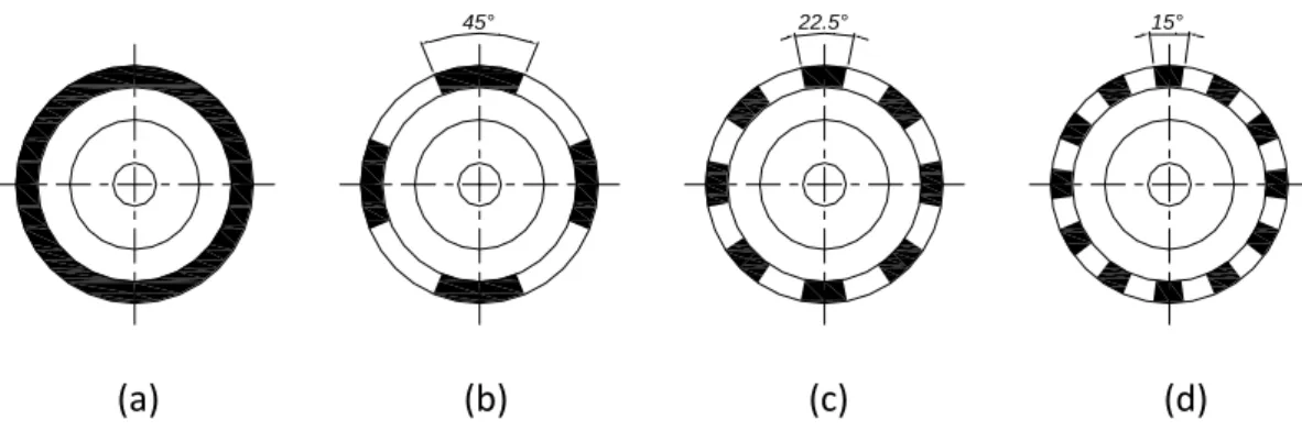
Four different configurations of elastomeric spatial distribution are analyzed. These configurations are shown in Figure 2.
(a) (b) (c) (d)
Figure 2. Elastomeric dampers geometries: (a) continuous cartridge (360°); (b) 4x45° sectors;
(c) 8x22,5° sectors; (d) 12x15° sectors.
It is important to notice the symmetry about the coordinate axis and that the volume of elastomeric material is the same for the three-segmented configurations.
The Finite Element program ANSYS,
version 12, has been used to model the system. 72 two-node, linear beam elements, based on the Timoshenko theory, BEAM188,
100 mm 1 - Journal 2 - Shaft 3 - Disc # 1 4 - Disc # 2 x y 2 3 1 bearing #1 L C bearing #2 L C 4 45° 22.5° 15°
are used to model the rotor (shaft, discs and journals).
Only bending is considered in this work, as a consequence, the axial displacement and the rotation about the longitudinal axis of the shaft is constrained in a manner that axial motion and torsion are suppressed.
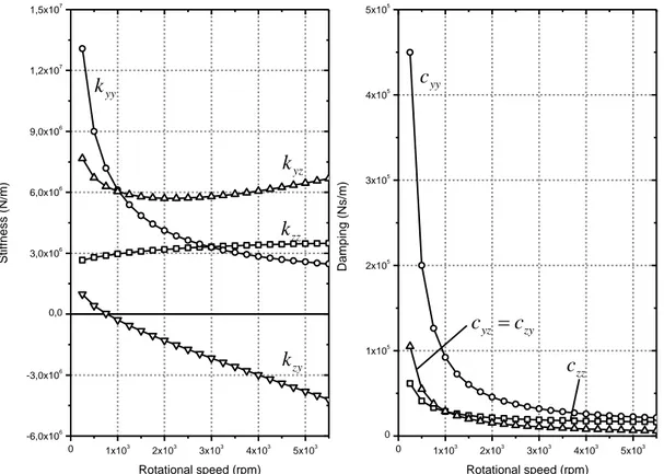
The dynamic characteristics of the bearings are represented by spring-damper elements, COMBI214. The stiffness and damping coefficients of the fluid film are
evaluated based on the short bearing assumption [1] and are presented in the
Figure 3. These coefficients are calculated for
250 rpm to 5500 rpm rotating speed range. The bearings have the following data: length
15
b
l mm, nominal inner diameter d b 60
mm, radial clearance c r 51 μm, oil viscosity
12, 4
mPa⋅s, and is subjected to a static
load F 73, 28N.
Figure 3. Dynamic properties of the journal bearing.
The bearing shells are meshed with SOLID186 elements with the properties of steel established
in Table 1. Its thickness is t b 15mm.
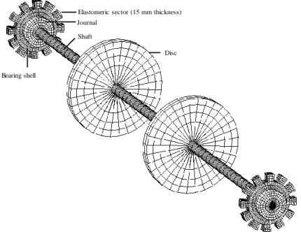
The elastomeric damper is modeled with SOLID186 elements. The mesh of the rotor-bearing-12x15° elastomeric damper is shown in Figure 4.
0 1x10³ 2x10³ 3x10³ 4x10³ 5x10³ -6,0x10⁶ -3,0x10⁶ 0,0 3,0x10⁶ 6,0x10⁶ 9,0x10⁶ 1,2x10⁷ 1,5x10⁷ 0 1x10³ 2x10³ 3x10³ 4x10³ 5x10³ 0 1x10⁵ 2x10⁵ 3x10⁵ 4x10⁵ 5x10⁵ S tif fn e s s ( N /m) Rotational speed (rpm) yy k yz k zz k zy k D a mping ( N s /m) Rotational speed (rpm) yy c zz c yz zy c c
Figure 4. Finite element mesh of the rotor-bearing-support system.
This meshing has been adopted after running successive refinements (h-method) and no significant changes in the amplitude of synchronous response were observed. The dampers are considered perfectly bonded to the bearing shell.
The essential boundary conditions consist in the restriction of all degrees of freedom of
the nodes located at the outer surface of the elastomers as shown in Figure 5.a. For the FFB (Fluid Film Bearing) reference model, the outer node of the COMBI214 elements has all its movements constrained (Figure 5.b).
(a) (b)
Figure 5. Essential boundary conditions: (a) 360° elastomeric damper model; (b) FFB model.
Two terms compounding a Prony series (Eq. 1) are used to represent the viscoelasticity: 0 1 ( ) i t n i i G t G e
(1)where G is the dimensionless relaxation
modulus, t is time, and i (relative modulus)
and i (relaxation time) are material
parameters. The relation Gi G0i is
calculated by ANSYS. The summation of the
Elastomeric sector (15 mm thickness)
Bearing shell Journal Shaft Disc J Journal I Foundation
moduli i shall be less or equal to 1,0. is
not direct inserted, but calculated from the
expression 1
i .For elastomers, the Poisson ratio is approximately 0,5 and the relation between the shear modulus and elastic modulus is
3
E G.
Three types of elastomers, named “Sample 30”, “Sample 50” and “Sample 70”, were tested. The hardness of Sample 70 is higher than the hardness of Sample 50 which
is higher than the hardness of Sample 30. In fact, the values 30, 50 and 70 correspond to the Shore A hardness of the samples published by the manufacturer. Their characteristics are shown on Table 2 and were obtained from tests performed in the Laboratory of Mechanical Systems of the School of Mechanical Engineering of the Federal University of Uberlândia [12].
Table 2. Properties of the viscoelastic materials.
Modulus of Elasticity (N/m2) Poisson ratio Density (kg/m3) 1 1 2 2 Sample 30 1,658E6 0,4998 1100 0,4168 0,1994 0,5832 0,0045 Sample 50 2,329E6 1150 0,3362 0,0986 0,6638 0,0034 Sample 70 2,810E6 1200 0,3140 0,0935 0,6860 0,0031
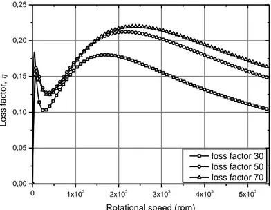
The variation of the loss factor, which is the ratio between the dissipated energy and the stored energy, with the frequency for the three elastomeric materials is shown in Figure 6.
Figure 6. Loss factor versus frequency.
RESULTS AND DISCUSSION The reference models
An unbalance of 5
95 10 kg·m as
introduced in the disc #1 (Fig. 1). The
amplitudes presented on the results correspond to the displacements on the node in which such unbalance force has been applied. 0 1x10³ 2x10³ 3x10³ 4x10³ 5x10³ 0,00 0,05 0,10 0,15 0,20 0,25 L o ss fa ct o r, Rotational speed (rpm) loss factor 30 loss factor 50 loss factor 70
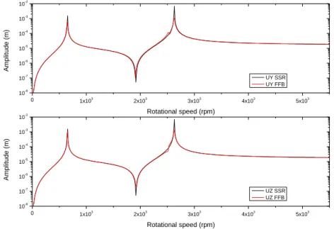
In Figure 7 the unbalance response of the FFB model is presented with a model of rotor
simply supported (SSR). The SSR
configuration is adopted for comparison
purposes. The effects of the stiffness and damping provided by the bearings are stressed.
Figure 7. Unbalance response of the SSR and FFB models. As expected, the amplitude of the
synchronous response of FFB model is lower compared to the SSR (Simple Supported
Rotor) model, due the damping provided by
the fluid film.
The SSR model presents peaks of 1.579 mm and 6.900 mm for the first (653.10 rpm) and second (2,629.68 rpm) critical speeds, respectively. The peak responses magnitudes for the FFB model are 0.714 mm in the y direction and 1.055 mm in the z direction for the first critical and 1.106 mm in the y direction and 1.323 mm in the z direction for the second critical speed.
The amplitude for the second critical diminishes with the use of fluid film bearing, but it still remains higher compared to the first critical speed.
One can observe that split critical speed occurs. It is a consequence of the difference of direct stiffness of the supports in the orthogonal directions. The split critical speed is more visible for the second critical speed and the peaks occur at 2517.96 rpm and
2621.10 rpm. The FFB model presents peaks at 635.94 rpm and at 653.10 rpm for the first critical speed.
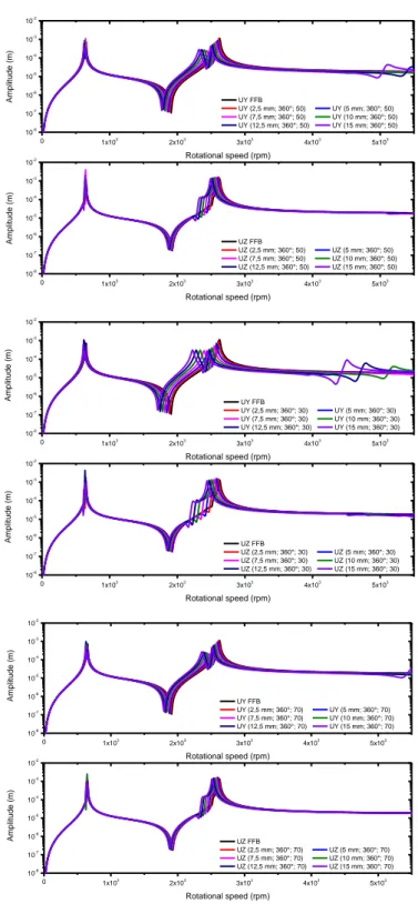
The models with elastomeric dampers
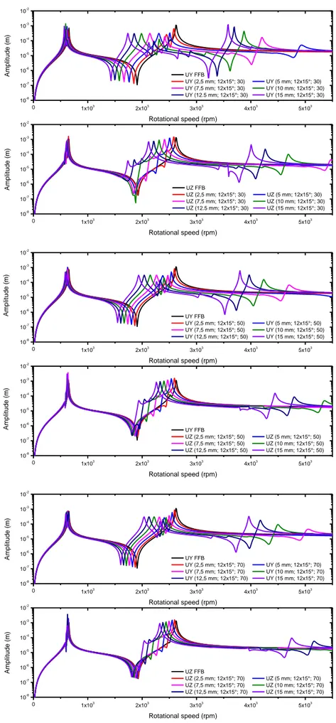
The amplitudes for the models with elastomeric dampers are presented in Figures 8 to 11. The first observation that can be made is that the critical speeds are shift toward zero. It indicates that the supports are more compliant than the FFB models.
The critical speed separation is more evident in the models with elastomeric dampers.
The compliance introduced by the viscoelastic material influences principally the second critical speed peak, reducing its value. One may also observes that some models present more than two critical speeds
also due the additional compliance
introduced by the viscoelastic cartridges. These influences are almost negligible for the first critical speed, therefore the bearings had low influence in the first mode shape. This
0 1x10³ 2x10³ 3x10³ 4x10³ 5x10³ 10-8 10-7 10-6 10-5 10-4 10-3 10-2 0 1x10³ 2x10³ 3x10³ 4x10³ 5x10³ 10-8 10-7 10-6 10-5 10-4 10-3 10-2 A mplit u d e ( m) Rotational speed (rpm) UY SSR UY FFB A mplit u d e ( m) Rotational speed (rpm) UZ SSR UZ FFB
statement is due the negligible displacement of the shaft in the bearings positions.
Some amount of damping has been introduced in the bearings by the viscoelastic cartridges; therefore the peaks for the second critical speeds have lower response amplitude than for FFB models. Second critical speeds have also wider response peaks, larger half power band width,
indicating the presence of more damping in the system.
From these results one concludes that the usage of viscoelastic cartridges can be useful for reduce the unbalance response amplitude even in the presence of new critical speeds, which can be a negligible undesirable effect if the machine never pass through those speeds.
Figure 8. Unbalance response of continuous cartridge.
0 1x10³ 2x10³ 3x10³ 4x10³ 5x10³ 10-8 10-7 10-6 10-5 10-4 10-3 10-2 0 1x10³ 2x10³ 3x10³ 4x10³ 5x10³ 10-8 10-7 10-6 10-5 10-4 10-3 10-2 A mplit u d e ( m) Rotational speed (rpm) UY FFB UY (2,5 mm; 360°; 50) UY (5 mm; 360°; 50) UY (7,5 mm; 360°; 50) UY (10 mm; 360°; 50) UY (12,5 mm; 360°; 50) UY (15 mm; 360°; 50) A mplit u d e ( m) Rotational speed (rpm) UZ FFB UZ (2,5 mm; 360°; 50) UZ (5 mm; 360°; 50) UZ (7,5 mm; 360°; 50) UZ (10 mm; 360°; 50) UZ (12,5 mm; 360°; 50) UZ (15 mm; 360°; 50) 0 1x10³ 2x10³ 3x10³ 4x10³ 5x10³ 10-8 10-7 10-6 10-5 10-4 10-3 10-2 0 1x10³ 2x10³ 3x10³ 4x10³ 5x10³ 10-8 10-7 10-6 10-5 10-4 10-3 10-2 A mplit u d e ( m) Rotational speed (rpm) UY FFB UY (2,5 mm; 360°; 30) UY (5 mm; 360°; 30) UY (7,5 mm; 360°; 30) UY (10 mm; 360°; 30) UY (12,5 mm; 360°; 30) UY (15 mm; 360°; 30) A mplit u d e ( m) Rotational speed (rpm) UZ FFB UZ (2,5 mm; 360°; 30) UZ (5 mm; 360°; 30) UZ (7,5 mm; 360°; 30) UZ (10 mm; 360°; 30) UZ (12,5 mm; 360°; 30) UZ (15 mm; 360°; 30) 0 1x10³ 2x10³ 3x10³ 4x10³ 5x10³ 10-8 10-7 10-6 10-5 10-4 10-3 10-2 0 1x10³ 2x10³ 3x10³ 4x10³ 5x10³ 10-8 10-7 10-6 10-5 10-4 10-3 10-2 A mplit u d e ( m) Rotational speed (rpm) UY FFB UY (2,5 mm; 360°; 70) UY (5 mm; 360°; 70) UY (7,5 mm; 360°; 70) UY (10 mm; 360°; 70) UY (12,5 mm; 360°; 70) UY (15 mm; 360°; 70) A mplit u d e ( m) Rotational speed (rpm) UZ FFB UZ (2,5 mm; 360°; 70) UZ (5 mm; 360°; 70) UZ (7,5 mm; 360°; 70) UZ (10 mm; 360°; 70) UZ (12,5 mm; 360°; 70) UZ (15 mm; 360°; 70)
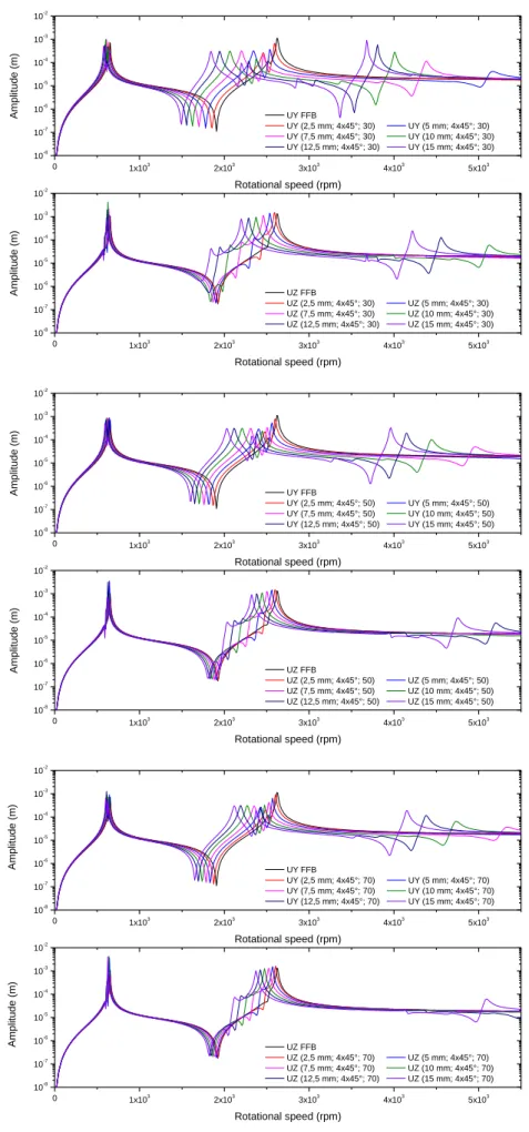
Figure 9. Unbalance response of 4x45° models. 0 1x10³ 2x10³ 3x10³ 4x10³ 5x10³ 10-8 10-7 10-6 10-5 10-4 10-3 10-2 0 1x10³ 2x10³ 3x10³ 4x10³ 5x10³ 10-8 10-7 10-6 10-5 10-4 10-3 10-2 A mplit u d e ( m) Rotational speed (rpm) UY FFB UY (2,5 mm; 4x45°; 30) UY (5 mm; 4x45°; 30) UY (7,5 mm; 4x45°; 30) UY (10 mm; 4x45°; 30) UY (12,5 mm; 4x45°; 30) UY (15 mm; 4x45°; 30) A mplit u d e ( m) Rotational speed (rpm) UZ FFB UZ (2,5 mm; 4x45°; 30) UZ (5 mm; 4x45°; 30) UZ (7,5 mm; 4x45°; 30) UZ (10 mm; 4x45°; 30) UZ (12,5 mm; 4x45°; 30) UZ (15 mm; 4x45°; 30) 0 1x10³ 2x10³ 3x10³ 4x10³ 5x10³ 10-8 10-7 10-6 10-5 10-4 10-3 10-2 0 1x10³ 2x10³ 3x10³ 4x10³ 5x10³ 10-8 10-7 10-6 10-5 10-4 10-3 10-2 A mplit u d e ( m) Rotational speed (rpm) UY FFB UY (2,5 mm; 4x45°; 50) UY (5 mm; 4x45°; 50) UY (7,5 mm; 4x45°; 50) UY (10 mm; 4x45°; 50) UY (12,5 mm; 4x45°; 50) UY (15 mm; 4x45°; 50) A mplit u d e ( m) Rotational speed (rpm) UZ FFB UZ (2,5 mm; 4x45°; 50) UZ (5 mm; 4x45°; 50) UZ (7,5 mm; 4x45°; 50) UZ (10 mm; 4x45°; 50) UZ (12,5 mm; 4x45°; 50) UZ (15 mm; 4x45°; 50) 0 1x10³ 2x10³ 3x10³ 4x10³ 5x10³ 10-8 10-7 10-6 10-5 10-4 10-3 10-2 0 1x10³ 2x10³ 3x10³ 4x10³ 5x10³ 10-8 10-7 10-6 10-5 10-4 10-3 10-2 A mplit u d e ( m) Rotational speed (rpm) UY FFB UY (2,5 mm; 4x45°; 70) UY (5 mm; 4x45°; 70) UY (7,5 mm; 4x45°; 70) UY (10 mm; 4x45°; 70) UY (12,5 mm; 4x45°; 70) UY (15 mm; 4x45°; 70) A mplit u d e ( m) Rotational speed (rpm) UZ FFB UZ (2,5 mm; 4x45°; 70) UZ (5 mm; 4x45°; 70) UZ (7,5 mm; 4x45°; 70) UZ (10 mm; 4x45°; 70) UZ (12,5 mm; 4x45°; 70) UZ (15 mm; 4x45°; 70)
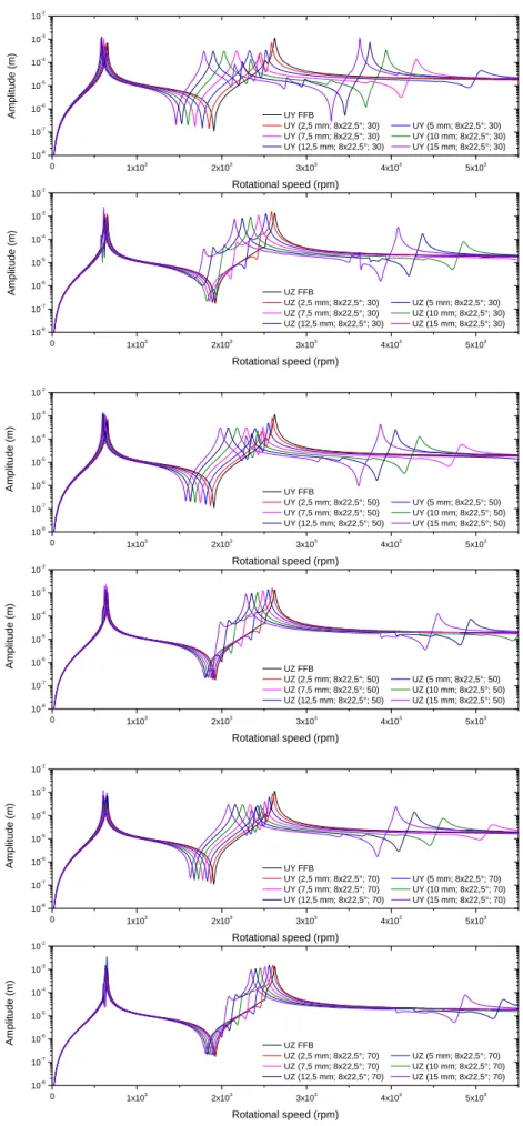
Figure 10. Unbalance response of 8x22,5° models. 0 1x10³ 2x10³ 3x10³ 4x10³ 5x10³ 10-8 10-7 10-6 10-5 10-4 10-3 10-2 0 1x10³ 2x10³ 3x10³ 4x10³ 5x10³ 10-8 10-7 10-6 10-5 10-4 10-3 10-2 A mplit u d e ( m) Rotational speed (rpm) UY FFB UY (2,5 mm; 8x22,5°; 30) UY (5 mm; 8x22,5°; 30) UY (7,5 mm; 8x22,5°; 30) UY (10 mm; 8x22,5°; 30) UY (12,5 mm; 8x22,5°; 30) UY (15 mm; 8x22,5°; 30) A mplit u d e ( m) Rotational speed (rpm) UZ FFB UZ (2,5 mm; 8x22,5°; 30) UZ (5 mm; 8x22,5°; 30) UZ (7,5 mm; 8x22,5°; 30) UZ (10 mm; 8x22,5°; 30) UZ (12,5 mm; 8x22,5°; 30) UZ (15 mm; 8x22,5°; 30) 0 1x10³ 2x10³ 3x10³ 4x10³ 5x10³ 10-8 10-7 10-6 10-5 10-4 10-3 10-2 0 1x10³ 2x10³ 3x10³ 4x10³ 5x10³ 10-8 10-7 10-6 10-5 10-4 10-3 10-2 A mplit u d e ( m) Rotational speed (rpm) UY FFB UY (2,5 mm; 8x22,5°; 50) UY (5 mm; 8x22,5°; 50) UY (7,5 mm; 8x22,5°; 50) UY (10 mm; 8x22,5°; 50) UY (12,5 mm; 8x22,5°; 50) UY (15 mm; 8x22,5°; 50) A mplit u d e ( m) Rotational speed (rpm) UZ FFB UZ (2,5 mm; 8x22,5°; 50) UZ (5 mm; 8x22,5°; 50) UZ (7,5 mm; 8x22,5°; 50) UZ (10 mm; 8x22,5°; 50) UZ (12,5 mm; 8x22,5°; 50) UZ (15 mm; 8x22,5°; 50) 0 1x10³ 2x10³ 3x10³ 4x10³ 5x10³ 10-8 10-7 10-6 10-5 10-4 10-3 10-2 0 1x10³ 2x10³ 3x10³ 4x10³ 5x10³ 10-8 10-7 10-6 10-5 10-4 10-3 10-2 A mplit u d e ( m) Rotational speed (rpm) UY FFB UY (2,5 mm; 8x22,5°; 70) UY (5 mm; 8x22,5°; 70) UY (7,5 mm; 8x22,5°; 70) UY (10 mm; 8x22,5°; 70) UY (12,5 mm; 8x22,5°; 70) UY (15 mm; 8x22,5°; 70) A mplit u d e ( m) Rotational speed (rpm) UZ FFB UZ (2,5 mm; 8x22,5°; 70) UZ (5 mm; 8x22,5°; 70) UZ (7,5 mm; 8x22,5°; 70) UZ (10 mm; 8x22,5°; 70) UZ (12,5 mm; 8x22,5°; 70) UZ (15 mm; 8x22,5°; 70)
Figure 11. Unbalance response of 12x15° models. 0 1x10³ 2x10³ 3x10³ 4x10³ 5x10³ 10-8 10-7 10-6 10-5 10-4 10-3 10-2 0 1x10³ 2x10³ 3x10³ 4x10³ 5x10³ 10-8 10-7 10-6 10-5 10-4 10-3 10-2 A mplit u d e ( m) Rotational speed (rpm) UY FFB UY (2,5 mm; 12x15°; 30) UY (5 mm; 12x15°; 30) UY (7,5 mm; 12x15°; 30) UY (10 mm; 12x15°; 30) UY (12.5 mm; 12x15°; 30) UY (15 mm; 12x15°; 30) A mplit u d e ( m) Rotational speed (rpm) UZ FFB UZ (2,5 mm; 12x15°; 30) UZ (5 mm; 12x15°; 30) UZ (7,5 mm; 12x15°; 30) UZ (10 mm; 12x15°; 30) UZ (12.5 mm; 12x15°; 30) UZ (15 mm; 12x15°; 30) 0 1x10³ 2x10³ 3x10³ 4x10³ 5x10³ 10-8 10-7 10-6 10-5 10-4 10-3 10-2 0 1x10³ 2x10³ 3x10³ 4x10³ 5x10³ 10-8 10-7 10-6 10-5 10-4 10-3 10-2 A mplit u d e ( m) Rotational speed (rpm) UY FFB UY (2,5 mm; 12x15°; 50) UY (5 mm; 12x15°; 50) UY (7,5 mm; 12x15°; 50) UY (10 mm; 12x15°; 50) UY (12,5 mm; 12x15°; 50) UY (15 mm; 12x15°; 50) A mplit u d e ( m) Rotational speed (rpm) UY FFB UZ (2,5 mm; 12x15°; 50) UZ (5 mm; 12x15°; 50) UZ (7,5 mm; 12x15°; 50) UZ (10 mm; 12x15°; 50) UZ (12,5 mm; 12x15°; 50) UZ (15 mm; 12x15°; 50) 0 1x10³ 2x10³ 3x10³ 4x10³ 5x10³ 10-8 10-7 10-6 10-5 10-4 10-3 10-2 0 1x10³ 2x10³ 3x10³ 4x10³ 5x10³ 10-8 10-7 10-6 10-5 10-4 10-3 10-2 A mplit u d e ( m) Rotational speed (rpm) UY FFB UY (2,5 mm; 12x15°; 70) UY (5 mm; 12x15°; 70) UY (7,5 mm; 12x15°; 70) UY (10 mm; 12x15°; 70) UY (12,5 mm; 12x15°; 70) UY (15 mm; 12x15°; 70) A mplit u d e ( m) Rotational speed (rpm) UZ FFB UZ (2,5 mm; 12x15°; 70) UZ (5 mm; 12x15°; 70) UZ (7,5 mm; 12x15°; 70) UZ (10 mm; 12x15°; 70) UZ (12,5 mm; 12x15°; 70) UZ (15 mm; 12x15°; 70)
Influence of the thickness of the elastomer
Analyses are carried out to investigate the influence of the viscoelastic cartridge's dimensions. The damper length is kept
constant, l e 15mm, and six thicknesses are
adopted: h e 2,5mm, h e 5mm, h e 7,5
mm, h e 10mm, h e 12,5mm, h e 15mm.
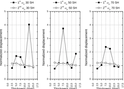
The influence of the damper thickness is shown in Figures 12 to 15. The amplitudes of the unbalance response are presented in the form of normalized displacements. For the first critical speed the normalization is defined by the ratio of the amplitude response of the model in analysis to the peak amplitude of the first critical speed of the FFB model. And for the second critical speed the normalization is obtained by the ratio of the amplitude response of the considered model to the peak amplitude of the FFB model for the second critical speed. It can be observed
that not all configurations succeed in reducing the peaks to values below the FFB model. Moreover, less than 20 % of the total number of the elastomeric models presents lower responses for the first and second
critical speeds, simultaneously, when
compared to the FFB model. From this observation, one can conclude that the suitable choice of the elastomeric material and the geometry of the damper are of most importance.
For the second critical speed, in general, one can state that the lower the thickness of the elastomer the higher the response amplitude. For the first critical such observation cannot be established, and a clear trend is not verified, the reason are again the low amplitude of the shaft displacement for this mode of shaft deformation.
Figure 12. Maximum amplitudes for different elastomeric thickness – 360° model.
0 ,0 2 ,5 5 ,0 7 ,5 1 0 ,0 1 2 ,5 1 5 ,0 1 7 ,5 0 1 2 3 4 5 0 ,0 2 ,5 5 ,0 7 ,5 1 0 ,0 1 2 ,5 1 5 ,0 1 7 ,5 0 1 2 3 4 5 0 ,0 2 ,5 5 ,0 7 ,5 1 0 ,0 1 2 ,5 1 5 ,0 1 7 ,5 0 1 2 3 4 5 N o rma lize d d isp la ce me n t Thickness (mm) 1stcr 30 SH 2nd cr 30 SH N o rma lize d d isp la ce me n t Thickness (mm) 1stcr 50 SH 2nd cr 50 SH N o rma lize d d isp la ce me n t Thickness (mm) 1stcr 70 SH 2nd cr 70 SH
Figure 13. Maximum amplitudes for different elastomeric thickness – 4x45° model.
Figure 14. Maximum amplitudes for different elastomeric thickness – 8x22,5° model.
Figure 15. Maximum amplitudes for different elastomeric thickness – 12x15° model.
0 ,0 2,5 5,0 7,5 1 0 ,0 1 2 ,5 1 5 ,0 1 7 ,5 0 1 2 3 4 5 0 ,0 2,5 5,0 7,5 1 0 ,0 1 2 ,5 1 5 ,0 1 7 ,5 0 1 2 3 4 5 0 ,0 2,5 5,0 7,5 1 0 ,0 1 2 ,5 1 5 ,0 1 7 ,5 0 1 2 3 4 5 N o rma lize d d isp la ce me n t Thickness (mm) 1stcr 30 SH 2nd cr 30 SH N o rma lize d d isp la ce me n t Thickness (mm) 1stcr 50 SH 2nd cr 50 SH N o rma lize d d isp la ce me n t Thickness (mm) 1stcr 70 SH 2nd cr 70 SH 0 ,0 2,5 5,0 7,5 1 0 ,0 1 2 ,5 1 5 ,0 1 7 ,5 0 1 2 3 4 5 0 ,0 2,5 5,0 7,5 1 0 ,0 1 2 ,5 1 5 ,0 1 7 ,5 0 1 2 3 4 5 0 ,0 2,5 5,0 7,5 1 0 ,0 1 2 ,5 1 5 ,0 1 7 ,5 0 1 2 3 4 5 N o rma lize d d isp la ce me n t Thickness (mm) 1st cr 30 SH 2ndcr 30 SH N o rma lize d d isp la ce me n t Thickness (mm) 1st cr 50 SH 2ndcr 50 SH N o rma lize d d isp la ce me n t Thickness (mm) 1st cr 70 SH 2ndcr 70 SH 0 ,0 2,5 5,0 7,5 1 0 ,0 1 2 ,5 1 5 ,0 1 7 ,5 0 1 2 3 4 5 0 ,0 2,5 5,0 7,5 1 0 ,0 1 2 ,5 1 5 ,0 1 7 ,5 0 1 2 3 4 5 0 ,0 2,5 5,0 7,5 1 0 ,0 1 2 ,5 1 5 ,0 1 7 ,5 0 1 2 3 4 5 N o rma lize d d isp la ce me n t Thickness (mm) 1stcr 30 SH 2ndcr 30 SH N o rma lize d d isp la ce me n t Thickness (mm) 1stcr 50 SH 2ndcr 50 SH N o rma lize d d isp la ce me n t Thickness (mm) 1stcr 70 SH 2ndcr 70 SH
Influence of the viscoelastic material
The influence of material is better observed in Figures 16 to 19. For the second critical speed, one can observe that, with some exceptions, the softer the material, the lower the peak response. For the first critical speed it is not possible to establish a trend.
Figure 16. Maximum amplitudes for different materials – 360° model.
Figure 17. Maximum amplitudes for different materials – 4x45° model.
Figure 18. Maximum amplitudes for different materials – 8x22,5° model.
30 SH 50 SH 70 SH 0 1 2 3 4 5 30 SH 50 SH 70 SH 0,0 0,5 1,0 1,5 2,5 mm; 1st cr 5 mm; 1 st cr 7,5 mm; 1st cr 10 mm; 1 st cr 12,5 mm; 1st cr 15 mm; 1 st cr N o rma lize d d isp la ce me n t Material 2,5 mm; 2nd cr 5 mm; 2 nd cr 7,5 mm; 2nd cr 10 mm; 2 nd cr 12,5 mm; 2nd cr 15 mm; 2 nd cr N o rma lize d d isp la ce me n t Material 30 SH 50 SH 70 SH 0 1 2 3 4 5 30 SH 50 SH 70 SH 0,0 0,5 1,0 1,5 2,5 mm; 1st cr 5 mm; 1 st cr 7,5 mm; 1st cr 10 mm; 1 st cr 12,5 mm; 1st cr 15 mm; 1 st cr N o rma lize d d isp la ce me n t Material 2,5 mm; 2nd cr 5 mm; 2 nd cr 7,5 mm; 2nd cr 10 mm; 2 nd cr 12,5 mm; 2nd cr 15 mm; 2 nd cr N o rma lize d d isp la ce me n t Material 30 SH 50 SH 70 SH 0 1 2 3 4 5 30 SH 50 SH 70 SH 0,0 0,5 1,0 1,5 2,5 mm; 1st cr 5 mm; 1 st cr 7,5 mm; 1st cr 10 mm; 1 st cr 12,5 mm; 1st cr 15 mm; 1 st cr N o rma lize d d isp la ce me n t Material 2,5 mm; 2nd cr 5 mm; 2 nd cr 7,5 mm; 2nd cr 10 mm; 2 nd cr 12,5 mm; 2nd cr 15 mm; 2 nd cr N o rma lize d d isp la ce me n t Material
Figure 19. Maximum amplitudes for different materials – 12x15° model. DISCUSSION
The rotating system analyzed in this paper presents the complexity inherent of a flexible rotor supported by fluid film bearings to which elastomeric dampers are added.
The system behavior depends on: the rotor characteristics, the dynamic properties of the fluid film and of the elastomeric material and the geometry of the damper device. It shall be stressed that the geometry of the elastomer influences the dynamic characteristics of the device, specially the stiffness. This dependency is translated by the “shape factor”, which quantifies the ability of the elastomer to react to an applied force by bulging at 90 degrees to the direction of the applied force.
The shape factor is calculated by developing the ratio of one side loaded surface to the total bulge area. A high shape factor indicates a poor ability to deform. A low shape factor indicates ability to deform. Implicit in a low shape factor is a low spring rate and the capability to have a low natural frequency.
The energy dissipated by an elastomeric device depends on the stiffness of the support system (elastomeric device, bearing, and structure) and on the deformations that occur in the elastomer itself, and also on the
material loss factor. Thus, an optimal value of the support stiffness and a high loss factor would induce lower responses.
The stiffness of the supports, including the bearings, has strong influence on the critical speeds. The use of elastomeric media shifts the critical speeds to lower values when compared to the FFB model. Depending on the magnitude of this shift, a region of lower material damping (translated by the loss factor) may be reached, resulting in a lower dissipation. This situation is particularly noticeable in the region of the first critical speed.
For the system presented in this work, the analysis of the dynamic behavior for the second critical speed is easier compared to the first critical. In second critical speed region, there are no significant changes in the dynamic properties of the fluid film. The presence of elastomeric devices makes the system less rigid compared to the model FFB. Consequently, there is a decrease of the critical speed. The lower the stiffness of the damper, the lower the critical speed. Thus, for the same dimensions, it is expected that the rotor with stiffer support material presents higher critical speeds as well as higher amplitude responses.
30 SH 50 SH 70 SH 0 1 2 3 4 5 30 SH 50 SH 70 SH 0,0 0,5 1,0 1,5 2,5 mm; 1st cr 5 mm; 1 st cr 7,5 mm; 1st cr 10 mm; 1 st cr 12,5 mm; 1stcr 15 mm; 1 st cr N o rma lize d d isp la ce me n t Material 2,5 mm; 2nd cr 5 mm; 2 nd cr 7,5 mm; 2nd cr 10 mm; 2 nd cr 12,5 mm; 2ndcr 15 mm; 2 nd cr N o rma lize d d isp la ce me n t Material
The analysis for the first critical speed is more complicated, because in a small range of variation of critical speed, the factors that influence dynamic behavior of the system undergo more intense changes.
The damping provided by the fluid film is higher in the region of the first critical speed when compared to the second critical speed and the viscoelastic loss factor is lower. Consequently, it is more difficult to improve the dynamic behavior (lower amplitudes in the present work) for the first critical speed.
The anisotropy of the film is more pronounced in the region of the first critical speed and the properties of the fluid film suffer strong variation. For some cases the peak response occurs in the y direction, reinforcing the influence of the properties of the lubricant film in that region. The loss factors are very low and its variation has a strong gradient. The loss factor of the Sample 50 is greater than the loss factor of the Sample 70 (Figure 6). This drastic variation of properties within a narrow frequency range helps to explain the lack of a clear trend on the dynamic behavior in the vicinity of the first critical speed. This requires that each case be studied more carefully in that region.
This complexity also helps to understand the difficulty in obtaining a theory fully accepted to design elastomeric dampers for rotating machines, making the synthesis of these devices a trial and error process. In this context the numerical methods, such as the Finite Element Method, appear as important analysis tools, allowing different situations be analyzed in a faster and economical way.
At this point another interesting
discussion appears. The knowledge of the properties of the elastomer is vital for the design of passive dampers based on the use of these materials. There is little data available regarding the properties of elastomers which can be directly used in numerical simulations. Except for some rare works, as a rule, the properties shall be determined by tests such as those conducted for this work.
Tests for obtaining viscoelastic properties require considerable effort and care with the experiment itself as well as in the curve fittings. It is possible that not all designers are able to perform these tests. This fact may be considered another limit to the use of elastomers in damping systems for rotating machinery.
CONCLUSIONS
The unbalance response amplitude of a rotor supported by fluid film bearings with elastomeric dampers may be lower when compared to the model with fluid film bearing. The success of the elastomeric damper is strong dependent of the suitable choice of the material and the geometry of the device.
To be effective under the dynamic point of view, a system with elastomeric damper shall have lower unbalance amplitude responses and have an extended safe operating range when compared to the reference FFB model. Due to the split critical and the occurrence of more critical speeds on the analyzed speed range, the models with elastomeric dampers present a reduce safety speed range. This fact shall be taken into account when designing this type of system.
Elastomers are prone to chemical degradation and aging. Even more, as other materials, they can failure by fatigue, structural instability and thermal induced phenomena. Although these factors were not account for in the present work, the authors stressed that in designing dampers with such materials a judicious analysis of the environment must be carried out.
The viscoelastic properties adopted in the models were obtained through laboratory tests conducted on “moderate” environment at constant temperature of 25 °C. Elastomeric materials are very sensitive to changes in temperature.
ACKNOWLEDGEMENTS
The authors would like to acknowledge the financial support received from Brazilian
Scientific Agencies as FAPEMIG, CNPq and Capes.
REFERENCES
[1] Vance, J.M., Rotordynamics of Turbomachinery1988: John Wiley & Sons.
[2] Genta, G., Dynamic of Rotating Systems2005: Springer.
[3] Powell, J.W. and M.C. Tempest, A Study of
High Speed Machines With Rubber Stabilized Air Bearings. Journal of Lubrication Technology, 1968. 90(4): p. 701-707.
[4] Darlow, M. and E. Zorzi, Mechanical Design
Handbook for Elastomers1981: MTI / NASA,
New York.
[5] Dutt, J.K. and B.C. Nakra, Vibration Response
reduction of a rotor shaft system using viscoelastic polimeric supports. Journal of
Vibration and Acoustics, 1992. 153: p. 221-223.
[6] Dutt, J.K. and B.C. Nakra, Vibration response
reduction of a rotor shaft system using viscoelastic polimeric supports. Journal of
Vibration and Acoustics, 1993. 153: p. 12. [7] Shabaneh, N.H. and J.W. Zu, Dynamic Analysis
of rotor-shaft systems with viscoelastic
supported bearings. Mechanism and Machinery Theory, 2000. 3: p. 1313-1330. [8] Bormann, A., Elastomerringe zur
Schwingungsberuhigung in der Rotordynamik - Theorie, Messungen und optimierte Auslegung., in Fakultät V - Verkehrs- und
Maschinensysteme der Technischen
Universität Berlin2005, Technischen Universität Berlin. p. 150.
[9] Cha, M., E. Kuznetsov, and S. Glavatskih, A
comparative linear and nonlinear dynamic analysis of compliant cylindrical journal bearings. Mechanism and Machine Theory,
2013. 64(0): p. 80-92.
[10] Thomazi, C.C., F.d.P. Lépore, and M.B.d. Santos, Unbalance Response of a Flexible
Rotor Supported by Fluid FIlm Bearings with Additional Viscoleastic Damping, in XIV Diname, ABCM, Editor 2011. p. 10.
[11] Thomazi, C.C., M.B.d. Santos, and F.P. Lépore.
Analysis of a rotor-bearing system with elastomeric dampers. in VII Congresso Nacional de Engenharia Mecânica CONEN 2012. 2012. São Luís.
[12] Lépore Neto, F.P. and M.B.d. Santos, A
Procedure for the Parametric Identification of Viscoelastic Dampers Accounting for Preload.
Journal of the Brazilian Society of Mechanical Sciences and Engineering, 2011. 33: p. 308-313.