Advances in Mechanical Engineering 2016, Vol. 8(4) 1–10
ÓThe Author(s) 2016 DOI: 10.1177/1687814016643885 aime.sagepub.com
Enhanced active dynamic balancing
of the planar robots using a
three-rotating-bar balancer
Kun Wang
1, Ke Li
1,2, Qiuju Zhang
1, Minzhou Luo
1and Peng Chen
2Abstract
The concept of full compensation against the resultant shaking forces and moments for arbitrary robots using a single active dynamic balancing mechanism is first addressed. And the application principle and general balancing conditions of the active dynamic balancing mechanism are presented. With the purpose of providing detailed description of these problems, a compact planar 3-degree-of-freedom active dynamic balancing mechanism is proposed. The active balancer is composed of three independent rotating bars with their respective actuators. The rotations of the three bars could change their center of gravity positions and then generate balancing forces for the unbalanced robots. Moreover, the changing of the angular acceleration of the bars can also generate a dynamic torque to balance the shaking moment. In order to present more detail of the balancing theory, the structure and kinematic and dynamic analysis of the proposed balancing mechanism are given. Finally, numerical examples illustrate the effectiveness of the proposed three-rotating-bar balancer.
Keywords
Active dynamic balancing, dynamics analysis, planar parallel mechanism, three-rotating-bar balancer
Date received: 23 June 2015; accepted: 6 March 2016
Academic Editor: Long Cheng
Introduction
Vibrations of a robot frame frequently occur when picking and placing payload or replacing various tools during operations, which result in shaking forces and shaking moments. As is well known, shaking forces and shaking moments are undesired since they cause fati-gue, noise disturbances, and deterioration in accuracy.1 Robots that can dynamically balance shaking forces and moments are expected to reduce wear, fatigue, noise, and cycle times and improve operating precision and control efficiency.2 Therefore, dynamic balancing of the shaking forces and shaking moments is of great significance in the development of robotic technology.
A robot is dynamically balanced if, for any motions of the robot, all of the resultant inertia forces and resul-tant moments are equal to zero.3 To make a robot
dynamically balanced, an effective method is to elimi-nate the source of the vibrations by changing the con-figuration of the machine. According to what is determined by mechanic, two methods are applied eliminating the adverse impact of the vibrations:passive dynamic balancing (without computer control) and active dynamic balancing (with computer control).4 Passive dynamic balance of a robot can be achieved by
1Jiangsu Key Laboratory of Advanced Food Manufacturing Equipment and
Technology, Jiangnan University, Wuxi, China
2Graduate School of Bioresources, Mie University, Tsu City, Japan
Corresponding author:
Ke Li, Jiangsu Key Laboratory of Advanced Food Manufacturing
Equipment and Technology, Jiangnan University, 1800 Li Hu Avenue, Wuxi 214122, Jiangsu Province, China.
Email: [email protected]
adjusting kinematic parameters such as the length or the mass of a link.5 With the operation of passive dynamic balancing mechanism, side effects inevitably are produced. A considerable amount of additional masses and additional inertia arise from the application of counter masses (CMs) and the accompanying mass redistribution in passive dynamic balancing, increasing the input power, manufacturing cost, and structural complexity.6–10Compared with passive dynamic balan-cing, the major advantage of active balancing with con-trol system is that all of the shaking forces and shaking moments can be simultaneously vanished by a mini-mum number of additional elements. Moreover, with the superiority of adaptability, active balancing is pos-sible to adjust balancing forces and balancing moments with changes of the mass and inertia parameters, which is available when mass and inertia change during pick-ing and placpick-ing payload or replacpick-ing tools.
The concept of active dynamic balancing has been proposed in recent years.11–13 Since dynamic perfor-mances can be influenced by controlling parameters such as gains of the proportional–integral–derivative (PID) controller and the adaptive controller, research-ers have adopted redundancy servo motor (RSM) to design path generator and improve dynamic perfor-mance for mechanisms including four-bar linkage and five-bar linkage.5Moreover, an approach of integrated design for dynamic balance concerning kinematic synthesis, dynamic performance, and input-speed tra-jectory is introduced to reduce the shaking force and moment.14,15In order to decrease the complexity of the controlling algorithm, some researchers have proposed that adding additional balancing units can help realize the dynamic balancing. One single dynamic balancing unit was proposed for 6 degrees of freedom (6-DOF) balancing and the structure of a planar parallel mechanism with 2-DOF rotations being used to move the counter-rotary counter mass was implemented for the application of a planar robot.16A balancing theory of mass balancing of mechanisms using a single rigid body was addressed and the balancing method was illu-strated.17An active disk with bevel gears and ball screw was designed for automatic active balancing of rotor-bearing systems.18A complex active dynamic balancer which consists of four independent controllable com-pensation inertias was implemented for a 2-DOF pla-nar mechanism.19
It is usual to use a disk to constitute an active dynamic balancing unit for active balancing of shaking moment in aforementioned methods.18,20And the disk is always designed to be with large mass to generate enough moment, resulting in energy consumption. In order to reduce addition of mass and inertia, a compact and light-weighted three-rotating-bar balancer with minimum additional mass and inertia is designed as an active dynamic balancing mechanism (ADBM) in this
study. With this structure, the rotation of three bars could render the change of the center of gravity posi-tion of the ADBM, which would generate 2-DOF bal-ancing forces on the base of robot. In addition, the variation of the angular acceleration of the bars can also generate a torque to balance the shaking moment of the robot. In order to verify the performance of the three-rotating-bar balancer, the application principle, structural design, and kinematic and dynamic analysis are given in this study, and simulations of dynamic bal-ancing with the mechanism are presented to illustrate the implementation and effectiveness of the ADBM.
General description of the dynamic
balancing
there arenindividual elements exerting shaking forces and shaking moments at the base of the robot, let FS and MS denote the independent resultant shaking forces and the resultant shaking moments, and they can be expressed in the matrix form
FS=½Fx,Fy,FzT= Xn i=1
mi€ri ð1Þ
MS=½Mox,Moy,MozT= Xn i=1
Ii€ui ð2Þ
wheremiandIiare the mass and the moment of inertia of theith shaking element,€riand€uiare the correspond-ing linear and angular acceleration vector in the fixed coordinate frame of the robot.
Because of the influence of the machine vibrations, the state of the base of the robot is no longer to be sta-tionary but to move with the shaking force and the shaking moment. In order to eliminate the machine vibrations, the balancing mechanism should produce three balancing forces and three balancing moments that are equal and opposite to the net shaking forces and net shaking moments.
For the purpose of generating balancing forces and balancing moments in each of the directions, three inde-pendent actively driven counter-rotating elements and three independent actively driven CMs are applied, which are illustrated as rotating disks and rectilinear sli-ders in Figure 1(b). The generalized balancing forces are represented by red arrows.
Design and kinematics of the ADBM
Actually, the 6 DOFs shown in Figure 1 are not balanced, respectively, by independent balancing ele-ments in engineering practices. In order to make the balancing mechanism more compact, the most com-mon method is combining (some of) the balancing ele-ments. An ultimate case is to balance all of the 6 DOFs with one single spatial spherical balancing element, as proposed by Van der Wijk and Herder.1The only dis-advantage of the design is that actuators of the sphere are not easily mounted and the 6 DOFs of the sphere are practically impossible to be simultaneously controlled.
This study presents the concept of a 3-DOF balancer which combines two CMs and one counter inertia (CI) for simultaneously force balancing and moment balan-cing of a planar x-y robot. To make the planar x-y robot to be dynamically balanced, two independent shaking forces and the vertical shaking moment should be balanced. Therefore, the balancing unit must be designed to be of 3-DOF.
CM and CI are the most common application of the basic mechanical design for balancing planar robots.
The movements of two CMs are designed to be recti-linear and mutually perpendicular to generate two bal-ancing forces in two directions. Since the motion of the CM should be of rectilinear guidance, and the two CMs are actuated to move on the tracks on the plat-form, the area occupation of the ADBM is demanded. As for the CI, a rotating disk is adopted aboutz-axis to balance the shaking moments. The high inertia always leads to high mass or large size, which results in high mass addition or large space demand of the ADBM. Obviously, it goes against the objective of reducing energy consumption and increasing ergonomics. In order to enhance the performance and simplify the structure of the ADBM, a compact three-rotating-bar planar linkage is presented for active dynamic balan-cing of a planar robot.
The ADBM is composed of three independent rotat-ing links, and its schematic is given in Figure 2. In order to eliminate the shaking forces and shaking moments of the planar robot, the ADBM is mounted on the base of the robot. The rotation of the links of the ADBM could exert forces on the base of the unbalanced robot for off-setting the shaking forces and making the robot dyna-mically balanced. Moreover, with the change of the rotation acceleration of the links, the angular momen-tum of the ADBM is no longer constant; it is thus able to generate a torque to offset the shaking moment of the robot.
As illustrated in Figure 2, all links of the ADBM are structurally similar but different in masses, lengths, and positions. mi, li, and ui represent the individual mass,
position of the center of mass, and initial rotation angle of theith link, respectively. The inertial frameQof the base of the robot is first established and then the posi-tion of the fixed protecposi-tion of theith rotating joint with
respect to Qis notedri, andri is a constant vector.pi denotes the position of the center of mass of linkiwith respect to originQ. Therefore, one has
pi=ri+liei,ei= cos
ui
sinui
, i=1,. . .,3 ð3Þ
The rotations of the links which lead to the changes of the linear momentum and angular momentum of the ADBM could contribute external force and external torque exerting to the base of the robot. The resultant inertia force F and resultant inertia moment M
gener-ated by the rotating links of the ADBM can be expressed in the matrix form as
F= d
dtP= d dt
Xn i=1
mip_i ð4Þ
M= d
dtL= d dt
Xn i=1 ~
pimip_i ð5Þ
where Pis the linear momentum and Lis the angular momentum of the ADBM with respect to theQ. mi pre-sents the mass of theith link of the ADBM.nis number of links and heren= 3.
According to equations (4) and (5), the balancing forces and balancing moments are influenced by the center of gravity positions of the links. And the center of gravity positions are determined by the locations of the links and then the forces and the moments are rela-tive to the rotation variables. Substituting the expres-sion of vectorPinto equations (4) and (5) leads to
F=
Pn i=1
mili(cosui(u_i)2)sinui€ui)
Pn i=1
mili(sinui(u_i)
2
) + cosui€ui)
2 6 6 4 3 7 7 5
ð6Þ
M= X
n
i=1
Iiu€i+mili( cosuiryi(u_i)2+ sinuiryi€ui
+ sinuirxi(u_i)2cosuirxi€ui)
ð7Þ
Here, u_i and€ui are indentified as variables specifying
the angular velocity and angular acceleration of the link i. In what follows these variables are used to form the components of two vectors, respectively, called the angu-lar velocity and anguangu-lar acceleration vector, namely
€
ui= €u1 €u2 €un
T
ð8Þ
(u_i)2= (u_1) 2
(u_2) 2
(u_n)2
h iT
ð9Þ
Therefore, equations (6) and (7) can be combined and written in matrices form
F M
=A€ui+B(u_i)2 ð10Þ
The matrices A and B after simplification can be expressed as follows
A=
m1l1sinu1 mnlnsinun
m1l1cosu1 mnlncosun
I1+m1l1rx1cosu1+m1l1ry1sinu1 In+mnlnrxncosun+mnlnrynsinun 2
4
3
5
B=
m1l1cosu1 mnlncosun
m1l1sinu1 mnlnsinun
m1l1( sinu1rx1cosu1ry1) mnln( sinunrxncosunryn)
2
4
3
5
The parameters of mi, ri, and li are constants and can be obtained through the constructive design of mechanism.
According to equation (10), the dynamic forceFand moment M are determined by the angular position, angular velocity, and angular accelerations of the links of ADBM. Therefore, the forces and moments applied by ADBM to the robot can be regulated by controlling the motion states of the links of the ADBM. If the net shaking forces and net shaking moments of robot are obtained, we can control the rotations of the links to generate expected balancing forces and moments that are equal and opposite to the shaking forces and shak-ing moments.
Dynamics analysis
The mechanism assumed to be influenced by the shak-ing forces and shakshak-ing moments which needs to be dynamically balanced is anx-yplanar robot. The three-bar ADBM is mounted on the base of the robot to make the mechanism dynamically balanced, as illu-strated in Figure 3. The inertial frame Ois first estab-lished and then a coordinate frameQis attached to the center of the robot base. fsx, fsy, and ts, respectively,
denote two independent resultant shaking forces and one resultant shaking moment applied to the planar robot.
and the net shaking moments such that the robot is dynamically balanced. To make the robot to be dyna-mically balanced, the reaction forces and torques at the base should be identically equal to zero. When the net shaking forces and the shaking moments acting on the machine frame are given, the ADBM should produce balancing forces and balancing moments that satisfy the following constraints
FB+FS=0 ð11Þ
MB+MS=0 ð12Þ
whereFBand MB denote the external force and exter-nal moment applied by the ADBM on the robot base. When the shaking forces and shaking moments are acquired, we can calculate the desired motion para-meters of the links of the ADBM according to the inverse kinematics equations.
According to equation (10), the inverse kinematics can be expressed as
€
ui= (A1) Fs
Ms
Bu_i2
ð13Þ
The desired rotational accelerations of the links of the ADBM can therefore be calculated according to equation (13). Then, appropriate parameters of the actuators used to move the links can be configured,
and the rotations of links of the ADBM can exert bal-ancing forces and balbal-ancing moments on the unba-lanced robot to make the robot dynamically baunba-lanced.
Determination of resultant shaking forces and
shaking moments
To get the inertia forces and torques of the platform, the net shaking forces and moments exert to the base of the robot must be obtained first. There are a lot of methods to get the vibrational signals.21–23 One effec-tive technology is to acquire the linear and angular accelerations of the shaking elements.
They can be obtained through mounting two accel-erometers on the rotating element to be detected. For each accelerometer, its acceleration can be expressed as follows
€
Pa=€ui+€uiErau_
2
ira ð14Þ
€
Pb=€ui+€uiErbu_
2
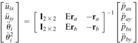
irb ð15Þ whereraandrbare the installation positions of acceler-ometeraandbrelative to the origin of the platform.€ui is the linear acceleration vector whileu_i and€ui are the
€ uix € uiy € ui _ u2 i 2 6 6 4 3 7 7 5
= I232 Era ra
I232 Erb rb
1 € pax € pay € pbx € pby 2 6 6 4 3 7 7 5
ð16Þ
where €pax, €pay, €pbx, and €pby are the x-direction and y-direction acceleration values from the readings of accelerometeraand accelerometerb.
Determination of the rotational variables
u
_
iand
u
i Rotational variables of each bar can be determined using an integration technique. First, the rotational velocityu_i to render the desired rotational accelerationcan be obtained with a zero-order-hold integration
_
ui(k) =u_i(k1) +€ui(k)Ts ð17Þ
And the rotation angle uican be obtained by twice integrating
ui(k) =ui(k1) +u_i(k1)Ts+1 2€ui(k)T
2
s ð18Þ wherekis the time step andTsis the sampling period.
Singularity analysis of matrix A
According to equation (10), when the number of the links is supposed to be three, both matrixAand matrix
Bare 3-by-3 matrices. In order to calculate the desired rotational accelerations of the links of the ADBM, what we need to do first is analyze the singularity of matrix A, which determines the probability of obtain-ment of any rotational acceleration solutions.
In order to obtain solutions of equation (13), matrix
A should be a nonsingular matrix. The singularity of matrix Adepends on whether its determinant is equal to zero. The determinant of matrixAcan be presented as follows
det (A2) =m1l1m2l2sin (u2u1)(I3+m3l 2 3)
+m1l1m3l3
sin (u1u3)(I2+m2l2 2)
+m2l2m3l3sin (u3u2)(I1+m1l 2 1)
ð19Þ
In order to ensure the three-bar linkage is available as an ADBM, the matrixAmust be nonsingular. That is, the following condition must be met
det (A2)6¼0 ð20Þ
Assuming that the three bars of the balancing mechanism are homogeneous, the moment of inertia of theith bar can be expressed as
Ii=
4 3mil
2
i, i=1,2,3 ð21Þ
Substituting equations (19) and (21) into equation (20), we obtain
det (A) = sin (u2u1)l3
+ sin (u1u3)l2+ sin (u3u2)l16¼0
ð22Þ
Numerical examples
In order to verify the ADBM proposed in this study, simulations by MAPLEä were performed. When the shaking forces and shaking moments are acquired by the accelerometers mounted on the robot to be balanced, the desired balancing forces and torque gen-erated by the ADBM can be determined. Then, the rotational accelerations of the bars of the ADBM can be calculated through inverse kinematics. The actuators will then actuate the ADBM according to the calcu-lated values and produce forces and moments that react on the unbalanced robot. By comparing the iner-tia forces and torques of the base of the robot with ADBM and without the ADBM, the effectiveness of the ADBM can be thus verified.
As illustrated in preceding sections, three motors and actuators are included respectively to drive the three independent bars. Therefore, the ADBM is com-posed of three independent rotating bars and their cor-responding actuators. The position and the way in which the actuator is mounted have influence on the balancing performance. For example, motors used for driving the bars can be mounted on the end of the links. Compared with mounting them on the base of the mechanism, their mass is advantageously used as a balancing mass which improves the effective balancing moment of inertia too. On account of motors being mounted on the end of the rotary bar, the three rotary bars of the ADBM should be designed different in lengths, such that rotating motors are unable to collide. The parameters of the bars of the ADBM are shown in Table 1. Moreover, in consideration of the essential conditions of the nonsingularAmatrix involved in sec-tion ‘‘Singularity analysis of matrix A,’’ the original angles of three bars should not be equal to each other, the random initial angles of each bar are given in Table 1 as well.
Table 1. Parameter configuration of the ADBM.
Number of the bar Mass Length Original angle
i= 1 m1= 1 kg l1= 0.35 m u1= 0.4p
i= 2 m2= 1.4 kg l2= 0.26 m u2= 0.9p
To illustrate the effectiveness of the ADBM, the robot is supposed to be subjected to the external shak-ing forces (alongx- and y-axes) and shaking moments (about thez-axis). Since the stochastic periodic motions of the shaking elements can be decomposed into a series of trigonometric functions using Fourier transforma-tion,2 the shaking forces and shaking moments that arise from shaking elements are formulated using sinu-soidal functions, as shown in Table 2. Regular shaking conditions are given in Case A, and extra disturbance terms are involved in Case B for purpose of testing the anti-interference performance and reliability of the ADBM, as well as demonstrating the adaptability of the active control, which allows dynamic balancing of variable payload.
The ADBM is assumed to be mounted on the base of the unbalanced robot which is subjected to the shak-ing forces and moments. In order to counteract the shaking influence, the bars of the ADBM should rotate along a planned trajectory to generate a balancing effect.
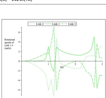
According to the given conditions of Case A, the calculation of the desired dynamic trajectory of each bar of ADBM can be accomplished by MAPLEä
. The curves of the desired rotational accelerations, rotational speeds, and rotation angles of three bars are, respec-tively, shown in Figures 4–6.
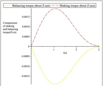
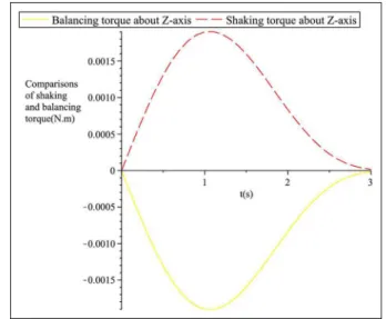
In order to demonstrate the applicability of the ADBM, it is easy to calculate the actual balancing forces and balancing moments applied by the ADBM. With the obtained motion parameters of the bars of the ADBM, the actual forces (along x- and y-axes) and shaking moments (about the z-axis) applied by the ADBM on the robot can be computed. Then, the results are shown to compare with the shaking forces and shaking moments in Figures 7 and 8.
Table 2. Two cases of resultant shaking forces and moments of the robot.
The resultant shaking forces and moments of the robot
Shaking force alongx-direction (N) Shaking force alongy-direction (N) Shaking moment (N m)
Case A fsx=1.25 sin(t)
+1.8 sin(2t)20.49 sin(3t)
fsy=0.9 sin(t)+0.5 sin(2t)
+0.7 sin(3t)
ts=0.0015 sin(t)+0.0007 sin(2t)
Case B fsx=1.25 sin(t)+1.8 sin(2t)
20.49 sin(3t)20.05 sin(12t)
fsy=0.9 sin(t)+0.5 sin(2t)
+0.7 sin(3t)20.02 sin(15t)
ts=0.0015 sin(t)+0.0007 sin(2t)
Figure 4. The desired rotational accelerations of Link 1–3 of
the ADBM under Case A. Figure 5. The desired rotational speeds of Link 1–3 of the ADBM under Case A.
Additionally, to test the anti-interference perfor-mance and reliability of the ADBM, extra disturbance terms are involved into the overall shaking forces and shaking moments of the robot in Case B. Similarly, the desired kinematic parameters of the bars of the ADBM under these circumstances also can be calculated. The results of desired rotational accelerations, rotational speeds, and rotation angles under Case B are, respec-tively, shown in Figures 9–11.
Next, the effectiveness and robustness of the ADBM are reconfirmed by comparing the generalized balan-cing forces with the shaking forces given in Case B. After obtaining the numerical solutions of the ADBM in given conditions of Case B, the summation forces Figure 7. The balancing forces and shaking forces applied to the robot under case A.
Figure 8. The balancing torque and shaking torque applied to the robot under case A.
Figure 9. The desired rotational accelerations of Link 1–3 of the ADBM under Case B.
Figure 10. The desired rotational speeds of Link 1–3 of the ADBM under Case B.
and moments that the ADBM and shaking elements exert to the base of the robot are, respectively, shown in Figures 12 and 13.
Figures 7, 8, 12, and 13 present the balancing forces and torques applied to the base of the robot in the three orthometric directions when giving variable shaking forces and torques. Inspecting Figures 7 and 8, the bal-ancing forces and moments generated by the rotation of three bars of ADBM are equal and opposite to the prescribed shaking forces and shaking moments, which means the summation of reaction forces and torques at the base of the robot is zero. It proves that the robot turns to be dynamically balanced with the three-rotat-ing-bar active balancing mechanism. Therefore, the effectiveness of the ADBM is primarily certified.
As for Case B, the shaking forces and shaking moments that exert on the robot are different from that in Case A. According to Figures 12 and 13, the resul-tant forces and moments of the robot and the ADBM are also equal to zero. That means the base of the robot could also be dynamically balanced with the effect of the ADBM even when the robot suffers stochastic dis-turbances. The dynamic balancing with respect to dif-ferent vibrations is therefore verified. The results demonstrate that dynamic balancing still can be achieved in spite of variations in the shaking elements. As a summary, the three-rotating-bar planar ADBM proposed in this study is able to realize the dynamic balancing of the platform and it can resist certain dis-turbances as well.
Conclusion and future research
For purpose of reducing or even eliminating the wear, fatigue, noise induced by vibrations, or brisk move-ments of machines and robots, it is preferable to make
the mechanism shaking force and shaking moment balanced. Taking the demands of a low addition of mass and inertia into consideration, an ADBM with computer controlled is adopted to achieve the require-ments in this study.
A novel and compact three-rotating-bar planar link-age is presented in this study as a balancing mechanism for active dynamic balancing of a planar robot. Numerical examples illustrated the effectiveness of the ADBM and the enhanced dynamic performance of the system.
Future research will focus on building a prototype of the mechanism for the purpose of demonstrating the implementation and effectiveness of active dynamic bal-ancing in practice. Dynamic balbal-ancing of picking and placing variable payload on the robot will be illustrated. Moreover, structural design of a spatial 6-DOF ADBM is attempted to be realized.
Acknowledgements
The authors would like to thank Clement Gosslin for his gui-dance and help.
Declaration of conflicting interests
The author(s) declared no potential conflicts of interest with respect to the research, authorship, and/or publication of this article.
Funding
The author(s) disclosed receipt of the following financial sup-port for the research, authorship, and/or publication of this article: The authors would like to acknowledge the financial support of the National Natural Science Foundation of China (Grant Nos 51505190 and 51575236). This work was also Figure 12. The balancing forces and shaking forces applied to
the robot under case B.
supported by Jiangsu Province Natural Science Foundation (Grant No. BK20150153), the open project of Jiangsu Key Laboratory of Advanced Food Manufacturing Equipment and Technology (Grant No. FM-201405 and FM-201501), and fundamental research funds for the central universities (Grant No. JUSRP51511).
References
1. Van der Wijk V and Herder JL. Force balancing of vari-able payload by active force-balanced reconfiguration of the mechanism. In:Proceedings of ReMAR, London, 22– 24 June 2009, pp.323–330. New York: IEEE.
2. Wang K, Luo M, Mei T, et al. Dynamics analysis of a three-DoF planar serial parallel mechanism for active dynamic balancing with respect to a given trajectory.Int J Adv Robot Syst2013; 10: 1–10.
3. Wu Y and Gosselin CM. On the dynamic balancing of multi-DoF parallel mechanisms with multiple legs. J Mech Design2007; 129: 234–238.
4. Van der Wijk V and Herder JL. Comparison of various dynamic balancing principles regarding additional mass and additional inertia. J Mechanisms Robot 2009; 1: 041006.
5. Sun Z, Zhang B, Cheng L, et al. Application of the redundant servomotor approach to design of path gen-erator with dynamic performance improvement. Mech Mach Theory2011; 46: 1784–1795.
6. Foucault S and Gosselin CM. Synthesis, design, and pro-totyping of a planar three degree-of-freedom reactionless parallel mechanism.J Mech Design2004; 126: 992–999. 7. Arakelian VH and Smith MR. Complete shaking force
and shaking moment balancing of linkages.Mech Mach Theory1999; 34: 1141–1153.
8. Chiou ST, Shieh MG and Tsai RJ. The two-rotating-mass balancers for partial balancing of spatial mechan-isms.Mech Mach Theory1997; 32: 617–628.
9. Yu Y-Q. Complete shaking force and shaking moment balancing of spatial irregular force transmission mechan-isms using additional links.Mech Mach Theory1988; 23: 279–285.
10. Arakelian VH and Smith MR. Shaking force and shak-ing moment balancshak-ing of mechanisms: a historical review with new examples.J Mech Design2005; 127: 334–339. 11. Lee S-H, Kim B-S, Moon J-K, et al. A study on active
balancing for rotating machinery using influence coeffi-cient method. In: Proceedings of IEEE international
symposium on computational intelligence in robotics and automation, Espoo, 27–30 June 2005, pp.659–664. New York: IEEE.
12. Kochev IS. Active balancing of the frame shaking moment in high speed planar machines.Mech Mach The-ory1992; 27: 53–58.
13. Gosselin CM, Mooreb B and Schicho J. Dynamic balan-cing of planar mechanisms using toric geometry.J Symb Comput2009; 44: 1346–1358.
14. Yan HS and Soong RC. Kinematic and dynamic design of four-bar linkages by links counterweighing with vari-able input speed. Mech Mach Theory 2001; 36: 1051–1071.
15. Yan HS and Yan GJ. Integrated control and mechanism design for the variable input-speed servo four-bar lin-kages.Mechatronics2009; 19: 274–285.
16. Van der Wijk V and Herder JL. Active dynamic balan-cing unit for controlled shaking force and shaking moment balancing. In:Proceedings of ASME 2010 inter-national design engineering technical conferences and com-puters and information in engineering conference, Volume 2: 34th annual mechanisms and robotics conference, Parts A and B, Montreal, QC, Canada, 15–18 August 2010, vol. 2, pp.1515–1522. New York: ASME.
17. Dresig H and Dien NP. Complete shaking force and shaking moment balancing of mechanisms using a mov-ing rigid body.Tech Mech2011; 31: 121–131.
18. Ortega AB, Carbajal FB, Contreras AF, et al. Active disk for automatic balancing of rotor-bearing systems. In:
Proceedings of American control conference, Seattle, WA, 11–13 June 2008, pp.3023–3028. New York: IEEE. 19. McCarthy JM. Introduction to theoretical kinematics.
Cambridge, MA: MIT Press, 1990, pp.67–73.
20. Huang Z and Shi ZD. Shaking moment balancing of link mechanisms. J Northeast Inst Heavy Mach 1986; 11: 40–46.
21. Radoslaw Z, Jacek U and Tomasz B. Measurement of instantaneous shaft speed by advanced vibration signal processing—application to wind turbine gearbox.Metrol Meas Syst2011; 18: 701–711.
22. Timusk M, Lipsett M and Mechefske CK. Fault detec-tion using transient machine signals.Mech Syst Signal Pr
2008; 23: 1724–1749.