Abstract
A cultural algorithm was utilized in this study to solve optimal design of truss structures problem achieving minimum weight objective under stress and deflection constraints. The algorithm is inspired by principles of human social evolution. It simulates the social interaction between the peoples and their beliefs in a belief space. Cultural Algorithm (CA) utilizes the belief space and popu-lation space which affects each other based on acceptance and influence functions. The belief space of CA consists of different knowledge components. In this paper, only situational and norma-tive knowledge components are used within the belief space. The performance of the method is demonstrated through four bench-mark design examples. Comparison of the obtained results with those of some previous studies demonstrates the efficiency of this algorithm.
Keywords
Cultural algorithm, Truss structure design, Size optimization.
A Cultural Algorithm for Optimal Design of Truss Structures
1 INTRODUCTION
In recent decades, various optimization techniques have been applied to optimal design of truss structure with stress and deflection constraints. The optimum design of truss structures are usually categorized into three different optimization problems: size, layout and topology optimizations. In the first category, only the cross sectional areas of the members are considered to minimize the weight of the structure, while the nodal coordinates of the truss are also taken as design variables in the layout optimization of truss structures. In the third category, the number of members of the structure and the connectivity of them are optimized. This paper focuses on the first category of truss optimum design problem, in which only sizing variables are considered as design variables.
Over the last years, the studies on meta-heuristic search methods such as Particle Swarm Opti-mization (PSO) (Eberhart and Kennedy, 1995), Ant Colony OptiOpti-mization (ACO) (Dorigo, 1992), Harmony Search (HS) (Geem et al., 2001), Simulated Annealing (SA) (Kirkpatrick et al., 1983) and Big Bang-Big Crunch (BB-BC) (Erol and Eksin, 2006) have shown that these methods can be
effi-Shahin Jalili a
Yousef Hosseinzadeh b
a
Young Researchers and Elite Club, Urmia Branch, Islamic Azad University, Urmia, Iran.
Faculty of Civil Engineering, University of Tabriz, Tabriz, Iran.
http://dx.doi.org/10.1590/1679-78251547
Latin A m erican Journal of Solids and Structures 12 (2015) 1721-1747
ciently used to solve engineering optimization problems characterized by non-convexity, discontinui-ty and non-differentiabilidiscontinui-ty. Most of these stochastic search methods are simulation of the specific phenomenon in the nature such as social behavior of bird flocking or fish schooling, evolution theo-ries of the universe and annealing processes in materials.
Researchers have been applied various meta-heuristic optimization algorithms to the optimal de-sign of truss structures. For example, Camp (2007) employed original BB-BC to size optimization of truss structures with continues and discrete design variables. Lamberti (2008) suggested a heuristic algorithm based on SA. Hasancebi et al. (2009) evaluated the performance of different algorithms in optimal design of pin jointed structures.
As extensions of meta-heuristic algorithms, hybrid algorithms have been developed to improve the performance of original meta-heuristic algorithms. The main aim of developing hybrid algo-rithms is to provide an adequate balance between the exploration and exploitation mechanisms. The exploration mechanism is related to the ability of algorithm to the performing efficient search in solution space of the optimization problem, while the exploitation mechanism is related to the ability of finding better solutions in the vicinity of the current solutions. Such hybrids have been successfully applied to optimal design of truss structures. For instance, Li et al. (2007) introduced a heuristic particle swarm optimizer (HPSO) for size optimization of truss structures. Kaveh and Talatahari (2009a) proposed particle swarm optimizer, ant colony strategy and harmony search scheme. This method is based on the particle swarm optimizer with passive congregation (PSOPC), ant colony optimization and harmony search scheme. Degertekin (2012) presented an efficient har-mony search algorithm (EHS) and self-adaptive harhar-mony search algorithm (SAHS) for sizing opti-mization of truss structures. In another work, Degertekin and Hayalioglu (2013) used teaching-learning-based optimization (TLBO) method for sizing truss structures which is a new meta-heuristic search method. TLBO simulates the social interaction between the learners and teacher. Kaveh and Talatahari (2009b, 2010a) proposed a hybrid big bang-big crunch (HBB-BC) by combin-ing BB-BC algorithm and with Sub Optimization Mechanism (SOM) for size optimization of space trusses and ribbed domes. In this method, SOM is an auxiliary tool which works as a search-space updating mechanism.
In some cases, researchers utilized novel optimization algorithms. For example, Kaveh and Talatahari (2010b,c,d, 2012) utilized Charged System Search (CSS) to optimal design of frame, gril-lage and skeletal structures and Imperialist Competitive Algorithm (ICA)) for size optimization of skeletal structures. And recently, Kaveh and Khayatazad (2013) employed Ray Optimizer (RO) to size and shape optimization of truss structures. Sonmez (2011) used Artificial Bee Colony (ABC) algorithm to sizing of truss structures.
Latin A m erican Journal of Solids and Structures 12 (2015) 1721-1747
deflection constraints and results are compared with different methods in order to show the efficacy of present approach.
The remainder of this paper is organized as: mathematical description of the optimum design problem is first reviewed in Section 2. Then, Section 3 presents a brief review of the CA. In Section 4, the effectiveness of CA is verified by four design examples. Finally, conclusions are presented in Section 5.
2 OPTIMUM DESIGN PROBLEM
The main aim of optimal design of a truss structure is to minimize the weight of the structure while satisfying some constraints on stresses and deflections. In this class of optimization problems, cross sectional areas are taken as design variables. The optimal design of a truss structure can be formu-lated as:
Find: A=[ A1,A2,…,And ]
(1) To minimize: W({A})=
Subjected to:
Where A is the vector containing the design variables; m is the number of members making up the
structureβ W(.) is the weight of the structureβ i is the material density of member i; Ai is the
cross-sectional area of the member i which is between Amin and Amax; Li is the length of the member i; nd
is the number of design variables; n is the number of nodes; and are the allowable tension and compressive stresses for member i, respectivelyβ i is the displacement of node iand minand max
are corresponding lower and upper limits.
Optimal design of truss structure should satisfy the above mentioned constraints. In this study, the constraints are handled by using a simple penalty function method. Thus, a fitness function must be given to evaluate the quality of a solution candidate. For each solution candidates, follow-ing cost function is defined:
(2)
(3)
Where fpenalty, is the penalty function represented by solution A, q is the number of constraints and
is the penalty factor which is related to the violation of constraints. In order to obtain the values
Latin A m erican Journal of Solids and Structures 12 (2015) 1721-1747
of , the stresses and nodal displacements of the structure are compared to the corresponding up-per or lower bounds as follow.
(4)
As it can be seen from Eq. (4), if the constraints are not violated, the value of the penalty function
will be zero. In Eq. (3), the values of parameters 1and 2 are selected considering the exploration and the exploitation rate of the search space. In this study 1is taken as unity, and 2 starts from 2 and gradually increases. The value of 2 for tth iteration is calculated as follow:
(5)
3 CULTURAL ALGORITHM
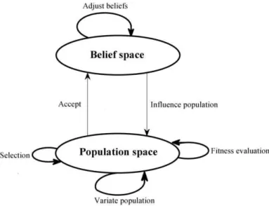
CA is a stochastic optimization technique originally developed by Reynolds (1991, 1999) inspired by theories of cultural evolution in sociology and archaeology. In fact, each society has a population and the individuals are the members of this population. The individuals of a society have cultural experiences that acquired by the previous generations. Culture can be seen as a set of ideological phenomena shared by a population (Peter et al., 2004), which consists of the beliefs, art and other things that acquired and transformed to the current generation by the previous generations. Soci-ologists believe that that the most of those forms of culture might be symbolically encoded and shared among the individuals of the society as a inheritance mechanism, and this mechanism may enhance the adaptability of the societies as well as accelerate the evolution speed of the society by making use of the domain knowledge obtained from generation to generation and spreading those useful information among all the individuals of the society (Youlin et al., 2011). Based on the described mechanism, the CA simulates the social interactions between the individuals of the popu-lation to develop a new optimization method. This algorithm uses the domain knowledge extracted during the optimization in order to bias the search process. As illustrated in Figure 1, CA utilizes two population and belief spaces which influence each other based on influence and acceptance functions. The population space consists of possible solution candidates to the optimization problem and the belief space records the cultural information about the behaviors and experiences of elites in the population space.
3.1 Belief Space
Latin A m erican Journal of Solids and Structures 12 (2015) 1721-1747
1. A Situational knowledge component, which is includes the best experience or solution gained by whole individuals in population space. This knowledge component is like global best in particle swarm optimization.
2. A Normative knowledge component, which is record the behaviors and experiences of accepted individuals from the population space and provide a set of intervals, one for each dimension of the problem. These intervals specify the ranges of search space which is good to search, and eliminate undesirable parts.
In addition, another three knowledge components can be added, such as domain knowledge, histori-cal knowledge and topographihistori-cal knowledge components (Reynolds and Saleem, 2000; Peng et al., 2003). But in this paper, only two knowledge components (Situational and Normative) are used in the belief space. Thus, the belief space expressed as the tuple:
Figure 1: Illustration of components of the Cultural algorithm.
B(t) = (S(t) , N(t)) (6)
Where S(t) and N(t) is the Situational and Normative knowledge components, respectively, and can be expressed as:
S(t) = {A*(t) }
N(t) = {X1,…,Xn }
(7)
(8)
For each dimension following information is stored:
Latin A m erican Journal of Solids and Structures 12 (2015) 1721-1747
Where, {A*(t)} is the vector of Situational design variables and nd is the number of design varia-bles. Ij(t) denotes the interval for design variable j, which is assigned
and for all design variables at the beginning time t=0. Lj (t) and Uj (t) represents the
scores for the lower and upper bounds of design variable j. Lj (t) and Uj (t) initialized to .
3.2 Acceptance Function
The acceptance function determines the number of solution candidates from the population space to adjust knowledge components of belief space. For this purpose there are two static and dynamic methods. In static method, the number of individuals that accepted to shape beliefs is fixed during the time, while in the dynamic methods changes with respect to time. In this paper, static method is employed to accept individuals to shape beliefs. Thus, the top %N of individuals based on fitness values is accepted to adjust the belief space.
3.3 Adjusting the Belief Space
The knowledge components of belief space are adjusted by selected individuals as follows:
3.3.1 Situational Knowledge
k=1,2,…,na (10)
Where W(.) is the weight of the structure, is the vector of kth accepted individual and na is the number of accepted individuals to adjust the belief space.
3.3.2 Normative Knowledge
(11)
(12)
(13)
Latin A m erican Journal of Solids and Structures 12 (2015) 1721-1747
3.4 Influence Function
The positions of individuals in the population space are updated by influence function. Reynolds and Chung (1997) proposed four influence function to update positions. In this paper, only following influence function is used:
=
i=1,2,..,ni , j=1,2,..,nd (15)
Where is the new solution at time t for individual i and variable j, N(0,1) is a normally distributed random variable with a mean of 0 and a standard deviation of 1, ni is the number of individuals used in population space, nd is the number of design variables and σij is the strategy
parameter for individual i and design variable j which is calculated as follow:
(16)
Where is the user defined parameter. Finally, the optimal design of truss structures with CA can
be summarized as following steps:
Step 1: Initialization
In this step, the initial population space is randomly generated between the lower and upper bounds for each design variable.
Step 2: Create and initialize the belief space.
The initial belief space created and initialized as explained in Section 3.1.
Step 3: Evaluation
Evaluation of each individual in population space and selecting the top %N of individuals based on the fitness values for adjust the belief space.
Step 4: Adjust Beliefs
In this step, the knowledge components of belief space are adjusted by accepted individuals as de-scribed in Section 3.3.
Step5: Influence population
In this step, the positions of individuals are updated by influence function as explained in Section 3.4.
Step 6: Finish or redoing
Latin A m erican Journal of Solids and Structures 12 (2015) 1721-1747
4 DESIGN EXAMPLES
In this section, four design examples have been conducted to assess the performance of the CA ap-proach for the optimal design of truss structures with stress and deflection constraints: 10-bar pla-nar truss, 25-bar spatial truss, 72-bar spatial truss and 120-bar dome truss. The performance of present algorithm is compared with some simple and improved algorithms from literature.
Figure 2: Scheme of the 10-bar planar truss.
In the all design examples, the population sizes of the algorithm are taken as 10, the number of
accepted individuals to adjust belief space is 4 and the value of parameter is chosen as uniformly
random number between 0 and 1. Due to stochastic nature of algorithm, the algorithm carries out independently for 10 times for each design example. Each run stops when the maximum structural analyses are reached. The maximum number of the structural analyses for each design example is different and it is depends on the dimension of the optimization problem. Therefore, the maximum structural analyses are set to 24,000 for example 1 and 20,000 for examples 2 and 3. For the last example, 12,000 structural analyses are considered.
The CA algorithm and direct stiffness method for analysis of truss structures have been imple-mented in MATLAB program and run in Dell Vostro 1520 with Intel CoreDuo2 2.66 GHz processor and 4 GB RAM memory.
4.1 A 10-bar Planar Truss
Latin A m erican Journal of Solids and Structures 12 (2015) 1721-1747
taken as 0.1 in2. In this design example, the loading condition is considered as: P1=150 kips and P2=50 kips.
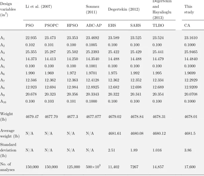
In Table 1, the results obtained by the CA are compared with those reported in the literature like PSO, PSOPC, HPSO, ABC-AP, EHS, SAHS and TLBO. From Table 1, it can be concluded that CA gives lightest design as compared to the results obtained by PSO, EHS, SAHS and TLBO, but heavier design than PSOPC, HPSO and ABC-AP methods. However, it is clear from Table 1 that the CA required significantly less structural analyses than PSOPC, HPSO and ABC-AP meth-ods. In addition, TLBO obtained 4678.31 lb after 14,875 structural analyses, while CA found the same weight after 10,510 structural analyses.
In addition, the convergence behaviors of the best solution and the average of 10 independent runs are shown in Figure 3.
Table 1: Optimized designs for the 10-bar planar truss. Design
variables (in2)
Li et al. (2007)
Sonmez
(2011) Degertekin (2012)
Degertekin and Hayalioglu (2013) This study
PSO PSOPC HPSO ABC-AP EHS SAHS TLBO CA
A1 22.935 23.473 23.353 23.4692 23.589 23.525 23.524 23.1610
A2 0.102 0.101 0.100 0.1005 0.100 0.100 0.100 0.1000
A3 25.355 25.287 25.502 25.2393 25.422 25.429 25.441 25.9465
A4 14.373 14.413 14.250 14.3540 14.488 14.488 14.479 14.4840
A5 0.100 0.100 0.100 0.1001 0.100 0.100 0.100 0.1000
A6 1.990 1.969 1.972 1.9701 1.975 1.992 1.995 1.9699
A7 12.346 12.362 12.363 12.4128 12.362 12.352 12.334 12.2929
A8 12.923 12.694 12.984 12.8925 12.682 12.698 12.689 12.9209
A9 20.678 20.323 20.356 20.3343 20.322 20.341 20.354 20.0708
A10 0.100 0.103 0.101 0.1000 0.100 0.100 0.100 0.1000
Weight
(lb) 4679.47 4677.70 4677.3 4677.077 4679.02 4678.84 4678.31 4678.01
Average
weight (lb) N/A N/A N/A N/A 4681.61 4680.08 4680.12 4681.5
Standard deviation (lb)
N/A N/A N/A N/A 2.51 1.89 1.016 3.86
No. of
analyses 150,000 150,000 125,000 500×10
Latin A m erican Journal of Solids and Structures 12 (2015) 1721-1747 Figure 3: Convergence diagrams for the 10-bar planar truss.
4.2 A 25-bar Spatial Truss Structure
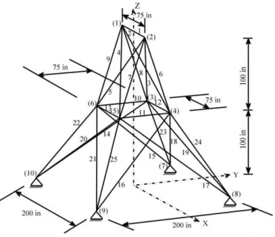
The second design example deals with the size optimization of a twenty-five-bar spatial truss structure shown in Figure 4. The Young’s modulus and material density of truss members are 104ksi and 0.1 lb/in3, respectively. Twenty five members are categorized into eight groups, as follows: (1) A1, (2) A2– A5, (3) A6– A9, (4) A10– A11, (5) A12– A13, (6) A14– A17, (7) A18 – A21,
and (8) A22– A25.
The spatial truss structure is subjected to the multiply loading condition as shown in Table 2. The maximum nodal displacements in all directions are limited to ±0.35 in for all free nodes. The allowable tension stresses are the same for the all design groups, but the allowable compressive stresses depend to the length of the members and it is different for each design group as shown in Table 3. The range of cross sectional areas varies from 0.01 in2 to 3.4 in2.
Latin A m erican Journal of Solids and Structures 12 (2015) 1721-1747 Figure 4: Scheme of the 25-bar spatial truss structure.
Node Condition 1 Condition 2
Px Py Pz Px Py Pz
1 0.0 20.0 -5.0 1.0 10.0 -5.0
2 0.0 -20.0 -5.0 0.0 10.0 -5.0
3 0.0 0.0 0.0 0.5 0.0 0.0
6 0.0 0.0 0.0 0.5 0.0 0.0
Note: loads are in kips.
Table 2: Loading conditions for the 25-bar spatial truss.
Table 3: Allowable stress values for the 25-bar spatial truss.
Element group Allowable compressive stress (ksi) Allowable tension stress (ksi)
1 35.092 40.0
2 11.590 40.0
3 17.305 40.0
4 35.092 40.0
5 35.092 40.0
6 6.759 40.0
7 6.959 40.0
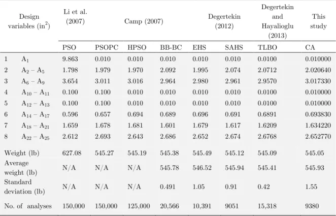
Latin A m erican Journal of Solids and Structures 12 (2015) 1721-1747 Table 4: Optimized designs for the 25-bar spatial truss. Design
variables (in2)
Li et al.
(2007) Camp (2007) Degertekin
(2012)
Degertekin and Hayalioglu
(2013)
This study
PSO PSOPC HPSO BB-BC EHS SAHS TLBO CA
1 A1 9.863 0.010 0.010 0.010 0.010 0.010 0.0100 0.010000
2 A2– A5 1.798 1.979 1.970 2.092 1.995 2.074 2.0712 2.020640 3 A6 – A9 3.654 3.011 3.016 2.964 2.980 2.961 2.9570 3.017330 4 A10– A11 0.100 0.100 0.010 0.010 0.010 0.010 0.0100 0.010000 5 A12– A13 0.100 0.100 0.010 0.010 0.010 0.010 0.0100 0.010000 6 A14– A17 0.596 0.657 0.694 0.689 0.696 0.691 0.6891 0.693830 7 A18 – A21 1.659 1.678 1.681 1.601 1.679 1.617 1.6209 1.634220 8 A22 – A25 2.612 2.693 2.643 2.686 2.652 2.674 2.6768 2.652770 Weight (lb) 627.08 545.27 545.19 545.38 545.49 545.12 545.09 545.05 Average
weight (lb) N/A N/A N/A 545.78 546.52 545.94 545.41 545.93
Standard
deviation (lb) N/A N/A N/A 0.491 1.05 0.91 0.42 1.55
No. of analyses 150,000 150,000 125,000 20,566 10,391 9051 15,318 9380
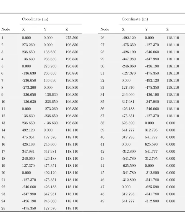
4.3 A 72-bar Spatial Truss Structure
A 72-bar spatial truss shown in Figure 6 is the third design example. The Young’s modulus and material density of truss members are 0.1 lb/in3 and 104 ksi, respectively. The 72 members of this spatial truss are divided into 16 groups using symmetry, as follows:
Latin A m erican Journal of Solids and Structures 12 (2015) 1721-1747 Figure 6: Scheme of the 72-bar spatial truss: (a) top and side view,
(b) element and node numbering pattern for first story.
Node Condition 1 Condition 2
Px Py Pz Px Py Pz
17 5.0 5.0 -5.0 0.0 0.0 -5.0
18 0.0 0.0 0.0 0.0 0.0 -5.0
19 0.0 0.0 0.0 0.0 0.0 -5.0
20 0.0 0.0 0.0 0.0 0.0 -5.0
Note: loads are in kips.
Latin A m erican Journal of Solids and Structures 12 (2015) 1721-1747 Table 6: Optimized designs for the 72-bar spatial truss. Design
Variables (in2)
Camp (2007)
Kaveh and Talatahari
(2009b)
Kaveh and Khayatazad (2013) Degertekin (2012) Degertekin and Hayalioglu (2013) This study
BB-BC HBB-BC RO EHS SAHS TLBO CA
1 A1 – A4 1.8577 1.9042 1.83649 1.967 1.860 1.90640 1.860930
2 A5 – A12 0.5059 0.5162 0.502096 0.510 0.521 0.50612 0.509300 3 A13 – A16 0.1000 0.1000 0.100007 0.100 0.100 0.10000 0.100000
4 A17– A18 0.1000 0.1000 0.10039 0.100 0.100 0.10000 0.100000
5 A19 – A22 1.2476 1.2582 1.252233 1.293 1.271 1.26170 1.262910 6 A20– A30 0.5269 0.5035 0.503347 0.511 0.509 0.51110 0.503970 7 A31– A34 0.1000 0.1000 0.100176 0.100 0.100 0.10000 0.100000 8 A35– A36 0.1012 0.1000 0.100151 0.100 0.100 0.10000 0.100000 9 A37– A40 0.5209 0.5178 0.572989 0.499 0.485 0.53170 0.523160 10 A41 – A48 0.5172 0.5214 0.549872 0.501 0.501 0.51591 0.525220 11 A49– A52 0.1004 0.1000 0.100445 0.100 0.100 0.10000 0.100010 12 A53 – A54 0.1005 0.1007 0.100102 0.100 0.100 0.10000 0.102540 13 A55– A58 0.1565 0.1566 0.157583 0.160 0.168 0.15620 0.155962
14 A59– A62 0.5507 0.5421 0.52222 0.522 0.584 0.54927 0.553490
15 A63– A70 0.3922 0.4132 0.435582 0.478 0.433 0.40966 0.420260 16 A71– A72 0.5922 0.5756 0.597158 0.591 0.520 0.56976 0.561500 Best weight
(lb) 379.85 379.66 380.458 381.03 380.62 379.63 379.69
Average weight
(lb) 382.08 381.85 382.5538 383.51 382.42 380.20 380.86
Standard
de-viation (lb) 1.912 1.201 1.2211 1.92 1.38 0.41 1.8507
Latin A m erican Journal of Solids and Structures 12 (2015) 1721-1747 Figure 7: Convergence diagrams for the 72-bar spatial truss.
(1)A1 – A4, (2) A5– A12, (3) A13 – A16, (4) A17 – A18, (5) A19 – A22, (6) A20– A30, (7) A31 – A34,
(8) A35 – A36, (9) A37 – A40, (10) A41 – A48, (11) A49 – A52, (12) A53 – A54, (13) A55 – A58, (14)
A59 – A62, (15) A63– A70, (16) A71– A72.
The spatial truss structure is subjected to the loading conditions given in Table 5. The maximum nodal displacements in all directions are limited to ±0.25 in for all free nodes. The minimum and maximum cross sectional areas for each member are 0.1 in2 and 4 in2, respectively.
The optimization results obtained by the CA are presented in Table 6 and are compared with those of the BB-BC, HBB-BC, RO, EHS, SAHS and TLBO approaches. From Table 6, it can be concluded that CA gives lightest design as compared to the results obtained by BB-BC, RO, EHS, SAHS and TLBO, but slightly heavier design than HBB-BC and TLBO methods. Moreover, the convergence diagrams of the best solution and the average of 10 independent runs are presented in Figure 7.
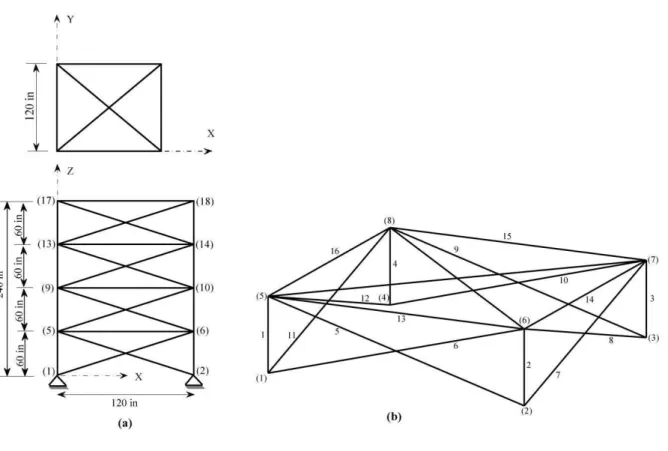
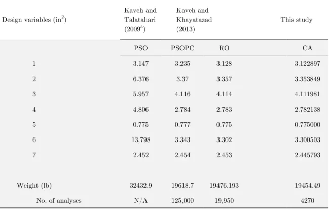
4.4 A 120-bar Dome Truss
The fourth design example is the size optimization of a 120-bar dome truss shown in Figure 8. Ta-ble 7 presents the nodal coordinates of this structure. The members of the structure are divided into 7 groups using symmetry as shown in Figure 8. The modulus of elasticity is 30,450 ksi, and the material density is 0.288 lb/in3. The yield stress of steel is taken as 58.0 ksi. The dome is subjected to the vertical loading at all free nodes. These loads are taken as −13.49 kips at node 1, −6.744 kips
at nodes 2 through 14, and −2.248 kips at the rest of the nodes. The minimum cross sectional area
Latin A m erican Journal of Solids and Structures 12 (2015) 1721-1747 Figure 8: Scheme of the 120-bar dome truss.
(1)Stress constraint (according to the AISC ASD (1989) code):
Latin A m erican Journal of Solids and Structures 12 (2015) 1721-1747
Where is calculated according to the slenderness ratio:
(18)
Coordinate (in) Coordinate (in)
Node X Y Z Node X Y Z
1 0.000 0.000 275.590 26 -492.120 0.000 118.110
2 273.260 0.000 196.850 27 -475.350 -127.370 118.110
3 236.650 136.630 196.850 28 -426.190 -246.060 118.110
4 136.630 236.650 196.850 29 -347.980 -347.980 118.110
5 0.000 273.260 196.850 30 -246.060 -426.190 118.110
6 -136.630 236.650 196.850 31 -127.370 -475.350 118.110
7 -236.650 136.630 196.850 32 0.000 -492.120 118.110
8 -273.260 0.000 196.850 33 127.370 -475.350 118.110
9 -236.650 -136.630 196.850 34 246.060 -426.190 118.110
10 -136.630 -236.650 196.850 35 347.981 -347.980 118.110
11 0.000 -273.260 196.850 36 426.188 -246.060 118.110
12 136.630 -236.650 196.850 37 475.351 -127.370 118.110
13 236.650 -136.630 196.850 38 625.590 0.000 0.000
14 492.120 0.000 118.110 39 541.777 312.795 0.000
15 475.351 127.370 118.110 40 312.795 541.777 0.000
16 426.188 246.060 118.110 41 0.000 625.590 0.000
17 347.981 347.981 118.110 42 -312.800 541.777 0.000
18 246.060 426.188 118.110 43 -541.780 312.795 0.000
19 127.370 475.351 118.110 44 -625.590 0.000 0.000
20 0.000 492.120 118.110 45 -541.780 -312.800 0.000
21 -127.370 475.351 118.110 46 -312.800 -541.780 0.000
22 -246.060 426.188 118.110 47 0.000 -625.590 0.000
23 -347.980 347.981 118.110 48 312.795 -541.780 0.000
24 -426.190 246.060 118.110 49 541.777 -312.800 0.000
25 -475.350 127.370 118.110
Latin A m erican Journal of Solids and Structures 12 (2015) 1721-1747
Where E = the modulus of elasticity; = the yield stress of steel; = the slenderness ratio ( )
dividing the elastic and inelastic buckling regions ; = the slenderness ratio
); k = the effective length factor; = the member length; and = the radius of gyra-tion. In addition, the radius of gyration ( ) can be expressed in terms of cross-sectional areas as
(Saka, 1990), in which and are the constants depending on the types of selected se
c-tions for the truss members. In this example, similar to the previous works, the pipe section (a=0.4993 and b=0.6777) is selected.
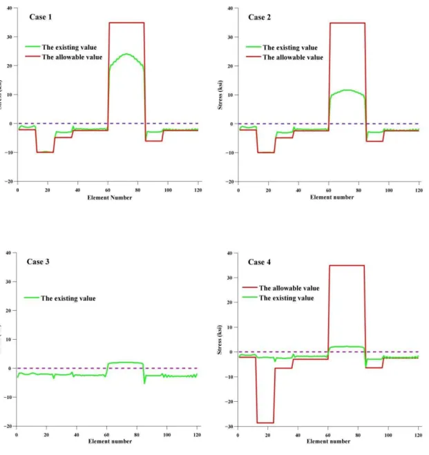
(2) The maximum nodal displacements are limited to 0.1969 in for all free nodes. In this example, four cases of constraints are considered as follows:
Case (1): with stress constraints and without any limitations of nodal displacement.
Case (2): with stress constraints and displacement limitations of ±0.1969 in imposed on all nodes in x- and y-directions.
Case (3): displacement limitation of ±0.1969 in only in z-direction and without stress constraints. Case (4): all constraints explained in cases 1, 2 and 3 are considered together.
Design variables (in2)
Kaveh and Talatahari (2009a)
Kaveh and Khayatazad (2013)
This study
PSO PSOPC RO CA
1 3.147 3.235 3.128 3.122897
2 6.376 3.37 3.357 3.353849
3 5.957 4.116 4.114 4.111981
4 4.806 2.784 2.783 2.782138
5 0.775 0.777 0.775 0.775000
6 13,798 3.343 3.302 3.300503
7 2.452 2.454 2.453 2.445793
Weight (lb) 32432.9 19618.7 19476.193 19454.49
No. of analyses N/A 125,000 19,950 4270
Latin A m erican Journal of Solids and Structures 12 (2015) 1721-1747 Design variables (in2) Kaveh and Talatahari
(2009a)
Kaveh and Khayatazad (2013)
This study
PSO PSOPC RO CA
1 15.978 3.083 3.084 3.0831690
2 9.599 3.639 3.360 3.3526138
3 7.467 4.095 4.093 4.0927515
4 2.790 2.765 2.762 2.7612602
5 4.324 1.776 1.593 1.5922992
6 3.294 3.779 3.294 3.2927453
7 2.479 2.438 2.434 2.4335890
Weight (lb) 41052.7 20681.7 20071.90 20064.69
No. of analyses N/A 125,000 19,950 7600
Table 9: Optimized designs for 120-bar dome truss (Case 2).
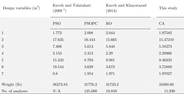
Table 10: Optimized designs for 120-bar dome truss (Case 3). Design variables (in2) Kaveh and Talatahari
(2009 a)
Kaveh and Khayatazad
(2013) This study
PSO PSOPC RO CA
1 1.773 2.098 2.044 1.97582
2 17.635 16.444 15.665 15.47210
3 7.406 5.613 5.848 5.58273
4 2.153 2.312 2.29 2.20966
5 15.232 8.793 9.001 9.46333
6 19.544 3.629 3.673 3.75880
7 0.8 1.954 1.971 1.97027
Weight (lb) 38273.83 31776.2 31733.2 31680.60
Latin A m erican Journal of Solids and Structures 12 (2015) 1721-1747 Table 11: Optimized designs for 120-bar dome truss (Case 4).
The optimal cross sectional areas obtained by the CA and the other optimization methods recently published in literature are reported in Table 8, Table 9, Table 10 and Table 11 for all cases. In Cas-es 1, 2 and 3, it is quite evident that CA givCas-es the lightCas-est dCas-esigns than other techniquCas-es in the literature based on Table 8, Table 9 and Table 10. For case 4, from Table 11, it can be concluded that CA gives the lightest design as compared to the results obtained by PSOPC, PSACO, HBB-BC, ICA and RO, but slightly heavier design than CSS method.
For all cases, Figures 9-12 compare the existing values (the member’s stresses corresponding to the best solution) and allowable values for stress and displacement constraints. Based on these fig-ures, it can be concluded that the stress and displacement constraints of the structure are not vio-lated and the presented optimum designs are completely feasible. In addition, it can be seen that the axial stresses in the most of the members of the structure are very close to the allowable values, which show the optimality of the presented designs.
Design variables
(in2) Kaveh and Talatahari (2009
a,b) Kaveh and Talatahari (2010c)
Kaveh and Khayatazad (2013)
This study
PSOPC PSACO HBB-BC ICA CSS RO CA
1 3.040 3.026 3.037 3.02750 3.027 3.030 3.02591
2 13.149 15.222 14.431 14.45960 14.606 14.806 14.7652
3 5.646 4.904 5.130 5.24460 5.044 5.440 5.08463
4 3.143 3.123 3.134 3.14130 3.139 3.124 3.13569
5 8.759 8.341 8.591 8.45410 8.543 8.021 8.43852
6 3.758 3.418 3.377 3.35670 3.367 3.614 3.35678
7 2.502 2.498 2.500 2.49447 2.497 2.487 2.49627
Weight (lb) 33481.2 33263.9 33287.9 33256.2 33251.9 33317.8 33253.95
Latin A m erican Journal of Solids and Structures 12 (2015) 1721-1747
Finally the convergence characteristics of the CA are shown in Figure 13 for all cases.
Latin A m erican Journal of Solids and Structures 12 (2015) 1721-1747
Latin A m erican Journal of Solids and Structures 12 (2015) 1721-1747
Latin A m erican Journal of Solids and Structures 12 (2015) 1721-1747 Figure 13: Convergence diagrams of the best results for the 120-bar dome truss (four Cases).
5 CONCLUSIONS
Latin A m erican Journal of Solids and Structures 12 (2015) 1721-1747
References
American Institute of Steel Construction (AISC) (1989). Manual of steel construction allowable stress design. 9th ed. Chicago, IL.
Camp, CV. (2007). Design of space trusses using big bang–big crunch optimization. Journal of Structural Engineer-ing;133:999–1008.
Dorigo, M. (1992). Optimization, learning and natural algorithms (in Italian), PhD Thesis. Dipartimento di Elettro-nica, Politecnico di Milano, IT.
Degertekin, S.O. (2012). An improved harmony search algorithms for sizing optimization of truss structures. Compu-ters and Structures 92–93:229–241.
Degertekin, S.O., Hayalioglu, M.S. (2013). Sizing truss structures using teaching-learning-based optimization. Com-puters and Structures 119:177-188.
Eberhart, RC., Kennedy, J. (1995). A new optimizer using particle swarm theory. In: Proceedings of the sixth inter-national symposium on micro machine and human science, Nagoya, Japan.
Erol OK., Eksin, I. (2006). New optimization method: big bang–big crunch. Advances in Engineering Soft-ware;37:106–111.
Geem, ZW., Kim, JH., Loganathan, GV. (2001). A new heuristic optimization algorithm: harmony search. Simula-tion 76:60–68.
Hasancebi, O., Carbas, S., Dogan, E., Erdal, F., Saka, MP. (2009). Performance evaluation of metaheuristic search techniques in the optimum design of real size pin jointed structures. Computers and Structures 87:284–302.
Kaveh, A., Talatahari, S. (2009 a). Particle swarm optimizer, ant colony strategy and harmony search scheme hybridized for optimization of truss structures. Computers and Structures 87:276-283.
Kaveh, A., Talatahari, S. (2009 b). Size optimization of space trusses using Big Bang–Big Crunch algorithm. Compu-ters and Structures 87:1129-1140.
Kaveh, A., Talatahari, S. (2010 a). Optimal design of Schwedler and ribbed domes via hybrid big bang–big crunch algorithm. Journal of Constructional Steel Research 66:412–419.
Kaveh, A., Talatahari, S. (2010 b). Charged system search for optimum grillage system design using the LRFD-AISCcode. Journal of Constructional Steel Research 66:767-771.
Kaveh, A., Talatahari, S. (2010 c). Optimal design of skeletal structures via the charged system search algorithm. Structural and Multidisciplinary Optimization 41:893–911.
Kaveh, A., Talatahari, S. (2010 d). Optimum design of skeletal structures using imperialist competitive algorithm. Computers and Structures 88:1220-1229.
Kaveh, A., Talatahari, S. (2012). Charged system search for optimal design of frame structures. Applied Soft Com-puting 12:382-393.
Kaveh, A., Khayatazad, M. (2013). Ray optimization for size and shape optimization of truss structures. Computers and Structures 117:82-94.
Latin A m erican Journal of Solids and Structures 12 (2015) 1721-1747 Li LJ., Huang ZB., Liu F., Wu QH. (2007). A heuristic particle swarm optimizer for optimization of pin connected structures. Computers and Structures 85:340–349.
Peng, B., Reynolds, R.G, Brewster, J. (2003). Cultural Swarms. In Proceedings of the IEEE Congress on Evolution-ary Computation, volume 3, pages 1965–1971, 2003.
Peter J., Richerson R., Boyd. (2004). Not By Genes Alone: How Culture Transformed Human Evolution, Univer-sity Of Chicago Press.
Reynolds, R.G. (1991). Version Space Controlled Genetic Algorithms. In Proceedings of the Second Annual Confer-ence on Artificial IntelligConfer-ence Simulation and Planning in High Autonomy Systems, pages 6–14.
Reynolds, R.G. (1999). Cultural Algorithms: Theory and Application. In D. Corne, M. Dorigo, and F. Glover, edi-tors, New Ideas in Optimization, pages 367–378. McGraw-Hill.
Reynolds, R.G., Chung, C. (1997). Knowledge-based Self-Adaptation in Evolutionary Programming using Cultural Algorithms. In Proceedings of the IEEE Congress on Evolutionary Computation, pages 71–76.
Reynolds, R.G., Saleem, S. (2000). Cultural Algorithms in Dynamic Environments. In Proceedings of the IEEE Congress on Evolutionary Computation, volume 2, pages 1513–1520.
Shahbazi, M.M., Gholipour, Y., Behnia, A. (2013). An improved version of inverse distance weighting metamodel assisted harmony search algorithm for truss design optimization. 10(2):263-282.
Sonmez, M. (2011). Artificial bee colony algorithm for optimization of truss optimization. Applied Soft Compu-ting;11:2406–2418.
Saka, MP. (1990). Optimum design of pin-jointed steel structures with practical applications. Journal of Structural Engineering 116:2599-2620.