Abstract
Ultimate compressive strength of welded stiffened aluminium plates under combined biaxial in-plane compression and different levels of lateral pressure is assessed herein. A numerical database of the ultimate strengths for stiffened aluminium plates is gener-ated at first. Then, regression analysis is applied in order to derive the empirical formulations as functions of two parameters, namely the plate slenderness ratio and the column (stiffener) slenderness ratio. The formulae implicitly include the effects of initial imper-fections and heat affected zone.
Keywords
Ultimate strength; Continuous stiffened aluminium plates; Biaxial compression; Lateral pressure; Empirical formulation; Heat-affected zone; Finite Element Method (FEM); Regression analysis.
Ultimate Strength of Continuous Stiffened Aluminium Plates
Under Combined Biaxial Compression and Lateral Pressure
NOMENCLATURE
a
Length of local plate panelsa1 to a2 Constant powers
b Breadth of local plate panels
c
Coefficient to define the maximum magnitude of the initial deflectionc1 to c3 Constant coefficients
d1 to d3 Constant coefficients
E Y”u“g’s m”dulus
Mohammad Reza Khedmati* a Hamid Reza Memarian a Manouchehr Fadavie a Mohammad Reza Zareei b
a Department of Marine Technology,
Amirkabir University of Technology, 424 Hafez Avenue, Tehran 15916-34311, Iran
b Shipbuilding Group, Faculty of
Engi-neering, Chabahar Maritime University, Chabahar 99717-56499, Iran
*Author e-mail: [email protected]
http://dx.doi.org/10.1590/1679-78251516
Latin A m erican Journal of Solids and Structures 12 (2015) 1698-1720
f
b Flange breadth of longitudinal stiffener
h Water head (pressure)
w
h Web height of longitudinal stiffener
I Moment of inertia of a stiffener with its attached plating
m1 to m6 Constant coefficients
n1 to n6 Constant coefficients
r
(A
I
) Radius gyration of a stiffener with its attached platingt(=tp) Plate thickness
f
t Flange thickness of longitudinal stiffener
w
t Web thickness of longitudinal stiffener
u
Displacement along x-axisv
Displacement along y-axisw
Displacement along z-axis0max
W
Maximum magnitude of initial deflection
(E
Y
t
b
) Slenderness parameter of the plate
(E Y r a
. ) Column slenderness parameter of the stiffened plate
P”iss”“’s rati”x
Average longitudinal strength at the ultimate limit statey
Average transverse strength at the ultimate limit stateuxq
Ultimate strength under combined longitudinal compression and lateral pressure obtainable from Khedmati et al. (2010)uyq
Ultimate strength under combined transverse compression and lateral pressure obtainable from Khedmati et al. (2014b)Y
Yield stressx
Rotation about x-axisy
Rotation about y-axisz
Rotation about z-axis
Latin A m erican Journal of Solids and Structures 12 (2015) 1698-1720
1 INTRODUCTION
Structural design of marine structures can be performed using either traditional allowable stress design (ASD) or limit state design (LSD). A great attention has been paid in recent years to-wards extending the wide range of applications of limit state design to some remaining marine structures, especially merchant ships.
Although large merchant ships are usually built in steel, aluminium alloys may be employed in construction of small-to-moderate size merchant ships. Owing to the differences that exist be-tween the behaviour of steels and that of aluminium alloys, available formulations for steel struc-tures cannot be directly applied to the aluminium strucstruc-tures, even with considering suitable con-version coefficients. That is why, there is a need to develop limit state equations specific to struc-tures made in aluminium alloys.
Stiffened aluminium plates as the main supporting elements in the structure of high-speed ships and also in the superstructures of the ships, are primarily required to resist against in-plane compressive forces acting along their length and/or breadth. Moreover, lateral pressure loading may also be present beside the in-plane loads. Ultimate limit state (ULS) is the main limit state governing the collapse of stiffened plates. The stiffened plates may experience different types of buckling failures when subjected to above-mentioned loads.
The ultimate strength of stiffened aluminium AA6082-T6 plates under the axial compression was investigated by Aalberg et al. (1998) using numerical and experimental methods. Hopperstad
et al. (1998) carried out a study with the objective of assessing the reliability of non-linear finite
element analyses in predictions on ultimate strength of aluminium plates subjected to in-plane compression. Some initial experimental and numerical simulations on the torsional buckling of flatbars in aluminium plates have been also performed by Zha et al. (2001) and also Zha and Moan (2003). A numerical benchmark study to present reliable finite element models to investi-gate the behaviour of axially compressed stiffened aluminium plates (including extruded profiles) was performed by Rigo et al. (2003).
Latin A m erican Journal of Solids and Structures 12 (2015) 1698-1720
This paper is a continuation of the studies made by Khedmati et al. (2010b, 2014b), in order to further develop empirical formulations for prediction of ultimate strength of continuous stiff-ened aluminium plates under combined biaxial in-plane compression and lateral pressure. The ultimate compressive strength data numerically obtained by the authors is used for deriving the formulations which are expressed as functions of two parameters, namely the plate slenderness ratio and the column (stiffener) slenderness ratio. Regression analysis is used in order to derive the empirical formulations. The formulae implicitly include the effects of weld induced initial im-perfections and softening in the heat affected zone.
2 ELASTIC_PLASTIC LARGE DEFLECTION ANALYSIS
A number of stiffened aluminium plate models are created in order to be analysed using finite ele-ment method.
2.1 Geometrical Characteristics of the Models
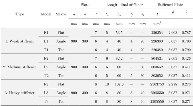
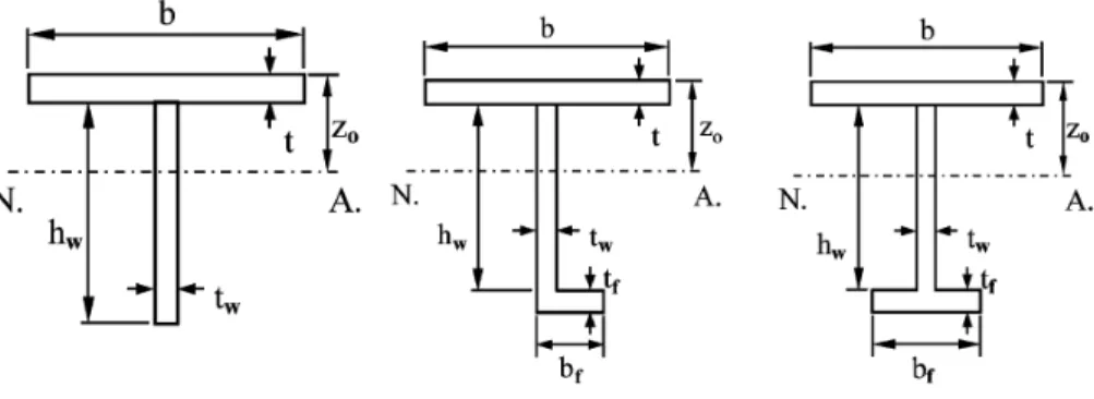
Three types of models are considered. Geometrical characteristics of all stiffened plate models are given in Table 1. In each type, three different shapes of stiffeners (Flat, Angle and Tee) have been attached to the isotropic plate, Figure 1. The stiffened plates of each type have the same moment of inertia. Types 1, 2 and 3 correspond respectively to weak, medium and heavy stiffen-ers.
Type Model Shape
Plate Longitudinal stiffener Stiffened Plate
a b t tw hw tf bf I β λ
mm mm mm mm mm mm mm mm4 - -
1: Weak stiffener
F1 Flat
900 300
7 5 53.5 --- --- 226254 2.603 0.787
L1 Angle 6 4 40 4 20 226380 3.037 0.790
T1 Tee 6 4 40 4 20 226380 3.037 0.790
2: Medium stiffener
F2 Flat
900 300
7 6 82.2 --- --- 804521 2.603 0.426
L2 Angle 6 5 60 5 30 803652 3.037 0.411
T2 Tee 6 5 60 5 30 803652 3.037 0.411
3: Heavy stiffener
F3 Flat
900 300
8 10 107.6 --- --- 2503753 2.278 0.273
L3 Angle 6 8 80 8 40 2505550 3.037 0.271
T3 Tee 6 8 80 8 40 2505550 3.037 0.271
Latin A m erican Journal of Solids and Structures 12 (2015) 1698-1720 Figure 1: Cross-sectional geometries of stiffened aluminium plates (Paik et al. 2008).
2.2 Finite Element Code and Details of Descretisations
ANSYS FEM program (2003) is utilised in order to perform elastic-plastic large deflection analy-ses on the stiffened aluminium plate models. Both material and geometric nonlinearities are taken into account. The four-node SHELL43 elements are used for discretisation of the stiffened plate models. The SHELL43 element has six degrees of freedom at each node: translations in the nodal x, y, and z directions and rotations about the nodal x, y, and z axes.
(a) Flat bar stiffened plate (b) Tee bar stiffened plate (c) Angle bar stiffened plate
Figure 2: Typical examples of the discretised stiffened plate models.
Based on the experience gained by Khedmati et al. (2009, 2010b), 300 elements are used to de-scretise each local plate panel (the panel surrounded by successive longitudinal or transverse stiff-eners), 6 to 7 and 5 to 6 elements are also considered respectively along web and flange stiffener. Figure 2 shows typical examples of the stiffener mesh models.
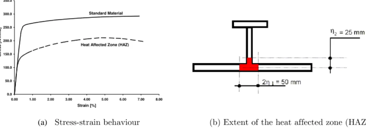
2.3 Mechanical Behaviour of Material
The Y”u“g m”dulus a“d the P”iss”“’s rati” ”f the aluminium alloy material are 70.475 GPa and
Latin A m erican Journal of Solids and Structures 12 (2015) 1698-1720
(a) Stress-strain behaviour (b) Extent of the heat affected zone (HAZ)
Figure 3: Stress-strain behaviour of the material and extent of the HAZ.
2.4 Extent of the Model, Boundary Conditions and Loading Sequence
In most of the studies regarding the buckling and ultimate strength of plates, an isolated plate surrounded between longitudinal stiffeners and transverse frames is considered assuming simply-supported boundaries around the plate. However, in continuous plating subjected to a high lateral pressure, the plate deflects in the same direction in all adjacent spans or bays. Therefore, for large lateral pressure the plate can be considered as clamped along its edges. As a result, according to the numerical studies on continuous ship bottom plating under combined in-plane compression and lateral pressure (Yao et al. 1998), both elastic buckling strength and ultimate strength be-come larger than those for the simply-supported isolated plates. Thus, continuous stiffened plate models are to be used in such analyses (Yao et al. 1998).
Figure 4: Extent of the continuous stiffened plate models for analysis in which q
is the lateral pressure acting perpendicularly on the plate region (Yao et al. 1998). 0.0
50.0 100.0 150.0 200.0 250.0 300.0 350.0
0.00 1.00 2.00 3.00 4.00 5.00 6.00 7.00 8.00 Strain [%]
S
tre
s
s
[
N
/mm
2
]
Standard Material
Latin A m erican Journal of Solids and Structures 12 (2015) 1698-1720 A double span- double bay (DS-DB) model (region abde in Figure 4) has been chosen for the analysis of stiffened aluminium plates with symmetrical stiffeners (Memarian 2011). For the analysis of the stiffened plates with non-symmetrical stiffeners, a double span-triple bay (DS-TB) model (region abgh in Figure 4) has been considered (Memarian 2011). The boundary conditions of the analysed models are as follow:
Periodically continuous conditions (equality of displacement along x-axis, displacement along z-axis, rotation about x-axis, rotation about y-axis and rotation about z-axis) are imposed at the same x-coordinate along the longitudinal edges in the triple bay models (i.e. along ab and gh). These conditions are defined as below:
a b gh
a b gh
x a b x gh
y a b y gh
z a b z gh
u u
w w
(1)
Symmetry conditions are imposed at the same x-coordinate along the longitudinal edges in the double bay models (i.e. along ab and de).
Symmetry conditions are imposed at the same y-coordinate along the transverse edges in the double span models (i.e. along adg and beh).
Although transverse frames are not modelled, the out-of-plane deformation of plate is re-strained along its junction line with the transverse frame.
To consider the plate continuity, in-plane movement of the plate edges in their perpendicular directions is assumed to be uniform.
After producing initial deflection in the stiffened plate models, lateral pressure is applied first on it until the assumed levels. Then, biaxial in-plane compression with different combinations of longitudinal/transverse stresses is exerted on the stiffened plate model.
Latin A m erican Journal of Solids and Structures 12 (2015) 1698-1720
(a) Coefficients for correction of maximum initial deflection in the plate panels
Figure 5: Procedure to generate initial deflection.
2.5 Initial Imperfections
In order to simulate the complex pattern of initial deflection (Yao et al. 1998), lateral pressure is applied first on the stiffened plate model and a linear elastic finite element analysis is carried out. Such an analysis is repeated in a trial and error sequence of calculations until the deflection of plate reaches to the average value given by equation (2).
t c
W0max
2 (2)The value of coefficient
c
depends on the level of initial deflection. Smith et al. (1987) proposed the maximum magnitude of initial deflection,W
0maxas follows:.
level severe for 2 3 . 0
level average for 2 1 . 0
level slight for 2 025 . 0
max 0
t t
t W
(3)
The relationships given in the equations (2) and (3) are usually employed for strength assessment of steel structures. However, they can also be generalised to the case of aluminium structures, provided that a suitable amount of the coefficient c is adopted. Based on the earlier studies made by Paik et al. (2008) and also those of Khedmati et al. (2010b) and Memarian (2011), the coeffi-cient c is assumed to be of the value of 0.05 reflecting the average value of initial deflection in ship plating evaluated by Varghese (1998). Thus, the final value of the maximum plate deflection is adopted as:
t
Latin A m erican Journal of Solids and Structures 12 (2015) 1698-1720 After satisfying this condition, the data information i.e the coordinates of nodal points, element coordinates and boundary conditions, are extracted and transferred to a new finite element mesh. The new model is used for a non-linear FEA analysis of the stiffened plate subjected to biaxial in-plane compression combined with variable levels of the lateral pressure. The procedure of generat-ing initial deflection is shown schematically in Figure 5 (a). After this step, lateral pressure is first applied until the assumed levels, before the application of in plane biaxial compression load (Me-marian 2011, Khedmati 2000).
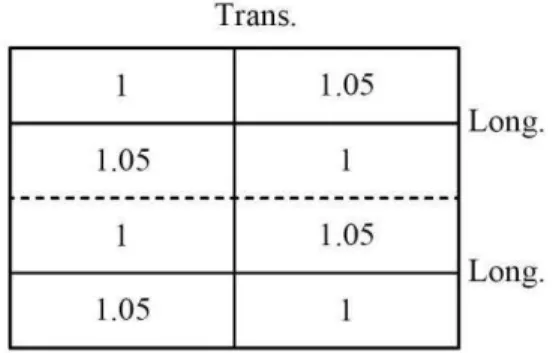
The values of maximum initial deflections in the adjacent local plate panels in the analysed mod-els are corrected with some experience-based coefficients as defined in the Figure 5 (b) (Khedmati 2000), in order to overcome divergence problems.
In addition to the initial deflections in the plate panels and successively in the attached stiffeners, material softening in the heat affected zones (HAZ) is taken into account.
2.6 Arc-length Method
The arc-length method is activated herein to help avoid bifurcation points and track unloading. This method causes the equilibrium iterations to converge along an arc, thereby often preventing divergence, even when the slope of the load versus deflection curve becomes zero or negative.
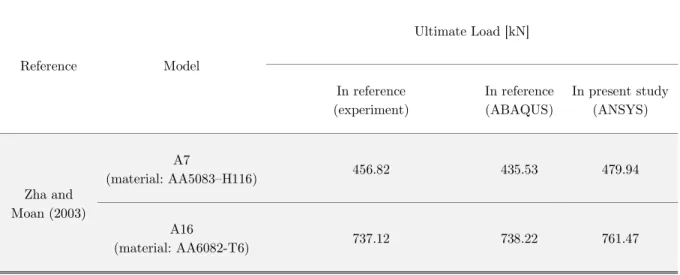
Reference Model
Ultimate Load [kN]
In reference (experiment)
In reference (ABAQUS)
In present study (ANSYS)
Zha and Moan (2003)
A7
(material: AA5083–H116) 456.82 435.53 479.94
A16
(material: AA6082-T6) 737.12 738.22 761.47
Table 2: Comparison of the ultimate strengths for the stiffened aluminium plates.
2.7 Validation of Numerical Model
Latin A m erican Journal of Solids and Structures 12 (2015) 1698-1720
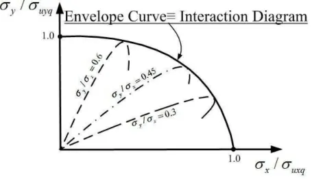
2.8 Demonstration of the Results
The full-range curves of
y (nondimensionalised by
uyq) versus
x (nondimensionalised byuxq
) are traced for various ratios of
y/
x in the current study. Three values of 0.30, 0.45 and 0.60 are assumed for the ratio of
y/
x. It should be emphasised that all of the models repre-sented in Table 1 have been already analysed by Khedmati et al. (2009, 2014a) under combined longitudinal compression and lateral pressure or under combined transverse compression and lat-eral pressure, respectively. The results of the calculations are drawn in a
y/
uyq-
x/
uxq coor-dinate system as shown in Figure 6. The two points with the coorcoor-dinates of (1.0, 0.0) and (0.0, 1.0) shown with solid circles in the Figure 6 represent the states of combined longitudinal com-pression and lateral pressure or combined transverse comcom-pression and lateral pressure, respec-tively. The next step will be drawing the envelope curve or the so-called Interaction Diagram i“ the Figure 6.Figure 6: A typical interaction diagram.
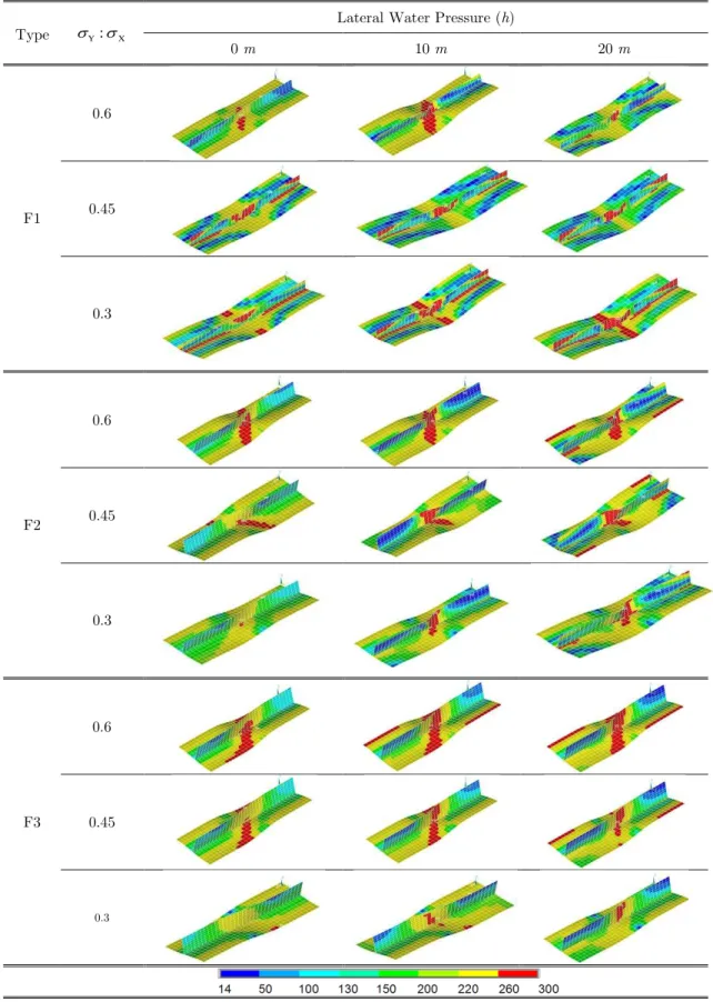
Latin A m erican Journal of Solids and Structures 12 (2015) 1698-1720
Latin A m erican Journal of Solids and Structures 12 (2015) 1698-1720 Lateral Water Pressure (h)
X Y
:
Type
20 m
10 m
0 m
0.6
F1 0.45
0.3
0.6
F2 0.45
0.3
0.6
F3 0.45
0.3
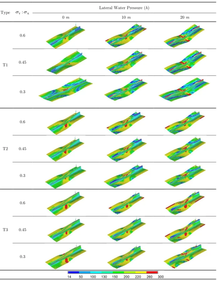
Latin A m erican Journal of Solids and Structures 12 (2015) 1698-1720 Lateral Water Pressure (h)
X Y
:
Type
20 m
10 m
0 m
0.6
T1 0.45
0.3
0.6
T2 0.45
0.3
0.6
T3 0.45
0.3
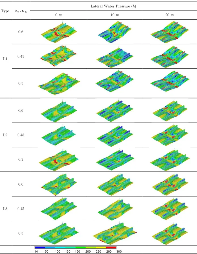
Latin A m erican Journal of Solids and Structures 12 (2015) 1698-1720 Lateral Water Pressure (h)
X Y
:
Type
20 m
10 m
0 m
0.6
L1 0.45
0.3
0.6
L2 0.45
0.3
0.6
L3 0.45
0.3
Latin A m erican Journal of Solids and Structures 12 (2015) 1698-1720
3 INTERACTION EQUATIONS
The following form or template is proposed for the interaction equation capable of predicting the ultimate strength of a continuous stiffened aluminium plate subject to combined biaxial compres-sion and lateral pressure:
1 2
1
a a y xu x q u y q
(5)where
1 1 2 3
2 1 2 3
a
c
c
c
a
d
d
d
(6) 6 5 2 4 3 3 4 2 5 1 3 , 2 ,1
m
h
m
h
m
h
m
h
m
h
m
c
6 5 2 4 3 3 4 2 5 1 3 , 2 ,
1
n
h
n
h
n
h
n
h
n
h
n
d
Performing the regression analysis on the previously-developed numerical database, different sets of the coefficients are derived.
3.1 Coefficients for the Case of Continuous Plates Stiffened with Flat-bar Stiffeners
The regression-based coefficients in this case would be as follows:
5 4 3 2
1
5 4 3 2
2
5 4 3 2
3
5 4
1
0.0003064 0.01943 0.4059 3.283 9.412 0.623
0.0008327 0.05268 1.087 8.392 21.22 2.524
0.0004671 0.02963 0.6226 5.146 15.61 0.6036
0.0001402 0.01094 0.2972
c h h h h h
c h h h h h
c h h h h h
d h h
3 2
3
5 4 3 2
2
5 4 3 2
3
3.227 11.05 4.963
0.000253 0.02003 0.5581 6.317 22.94 12.8
0.0002563 0.01987 0.5348 5.725 19.24 10.44
n h h h
d h h h h h
d h h h h h
(7)
3.2 Coefficients for the Case of Continuous Plates Stiffened with Tee-bar Stiffeners
The regression-based coefficients in this case would be as follows:
5 4 3 2
1
5 4 3 2
2
3
5 4 3 2
1
5 2
0.0000214 0.001419 0.03214 0.2939 0.8668 0.3475
0.0002272 0.01515 0.3446 3.154 9.15 0.8782
0
0.0000315 0.002311 0.06008 0.6606 2.614 0.6068
0.0002977 0.0
c h h h h h
c h h h h h
c
d h h h h h
d h
4 3 2
3
2186 0.5689 6.255 24.5 3.262
0
h h h h
Latin A m erican Journal of Solids and Structures 12 (2015) 1698-1720
3.3 Coefficients for the Case of Continuous Plates Stiffened with Angle-bar Stiffeners
The regression-based coefficients in this case would be as follows:
5 4 3 2
1
5 4 3 2
2
3
5 4 3 2
1
5 2
0.0002218 0.01432 0.3053 2.464 6.241 0.6558
0.0006212 0.04009 0.8545 6.89 17.34 1.918
0
0.0000213 0.001533 0.03821 0.3895 1.381 0.4285
0.0001589 0.01123
c h h h h h
c h h h h h
c
d h h h h h
d h h
4 3 2
3
0.2742 2.713 9.535 5.308
0
h h h
d
(9)
4 VERIFICATION
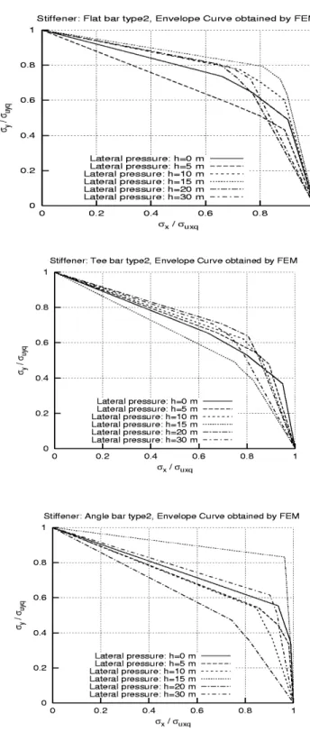
The interaction equation (5) together with the powers (6) and coefficients (7) to (9) are now used to predict the ultimate strength of all models defined in Table 1 when subjected to different combina-tions of in-plane compression and lateral pressure. The numerical values of the ultimate strength for the analysed models are given in the Tables 6 to 8. In addition, comparison of the envelope curves predicted using the empirical interaction equations with those obtained using FEM for some typi-cal cases is demonstrated in the Figure 10. As can be realised, a relatively good correlation can be observed among the results.
5 CONCLUSIONS
The aim of the present paper has been to develop closed form formulations for predicting ultimate compressive strength of stiffened aluminium plates under combined biaxial in-plane compression and lateral pressure. Extensive numerical results on welded stiffened aluminium plate structures obtained through a series of elastic-plastic large deflection FEM analyses were used for this pur-pose.
Latin A m erican Journal of Solids and Structures 12 (2015) 1698-1720
Lateral Water Pressure (h)
20 m 10 m 0 m Empirical Formula FEM Empirical Formula FEM Empirical Formula FEM Y uyq Y uyq X uxq Y uyq Y uyq X uxq Y uyq Y uyq X uxq Y X λ β Type Stiffener 1 1 0 1 1 0 1 1 0 1.0:0.0 0.787 2.603 F1 F bar 0.844 0.769 0.924 0.855 0.841 0.762 0.454 0.736 0.743 0.60 0.620 0.510 0.992 0.673 0.642 0.859 0.202 0.637 0.879 0.45 0.497 0.408 0.998 0.574 0.589 0.975 0.071 0.589 0.949 0.30 0 0 1 0 0 1 0 0 1 0.0:1.0 1 1 0 1 1 0 1 1 0 1.0:0.0 0.426 2.603 F2 0.948 0.804 0.651 0.777 0.774 0.725 0.721 0.735 0.660 0.60 0.913 0.728 0.715 0.709 0.698 0.805 0.633 0.643 0.772 0.45 0.864 0.629 0.776 0.608 0.601 0.889 0.478 0.489 0.902 0.30 0 0 1 0 0 1 0 0 1 0.0:1.0 1 1 0 1 1 0 1 1 0 1.0:0.0 0.273 2.278 F3 0.946 0.843 0.610 0.839 0.833 0.607 0.784 0.789 0.569 0.60 0.879 0.733 0.749 0.747 0.738 0.732 0.679 0.697 0.714 0.45 0.789 0.621 0.848 0.598 0.587 0.862 0.491 0.497 0.881 0.30 0 0 1 0 0 1 0 0 1 0.0:1.0
Latin A m erican Journal of Solids and Structures 12 (2015) 1698-1720
Lateral Water Pressure (h)
20 m 10 m 0 m Empirical Formula FEM Empirical Formula FEM Empirical Formula FEM Y uyq Y uyq X uxq Y uyq Y uyq X uxq Y uyq Y uyq X uxq Y X λ β Type Stiffener 1 1 0 1 1 0 1 1 0 1.0:0.0 0.790 3.037 T1 T bar 0.638 0.717 0.877 0.742 0.751 0.845 0.0.641 0.660 0.658 0.60 0.472 0.630 0.914 0.718 0.700 0.923 0.546 0.534 0.819 0.45 0.375 0.469 0.933 0.563 0.609 0.970 0.404 0.414 0.950 0.30 0 0 1 0.032 0 1 0 0 1 0.0:1.0 1 1 0 1 1 0 1 1 0 1.0:0.0 0.411 3.037 T2 0.787 0.707 0.694 0.682 0.622 0.783 0.660 0.653 0.639 0.60 0.648 0.638 0.804 0.577 0.506 0.861 0.546 0.532 0.796 0.45 0.580 0.530 0.844 0.401 0.411 0.945 0.353 0.368 0.947 0.30 0 0 1 0 0 1 0 0 1 0.0:1.0 1 1 0 1 1 0 1 1 0 1.0:0.0 0.271 3.037 T3 0.455 0.668 0.661 0.596 0.648 0.665 0.619 0.616 0.679 0.60 0.363 0.540 0.778 0.465 0.530 0.797 0.536 0.529 0.781 0.45 0.277 0.386 0.868 0.324 0.380 0.902 0.359 0.341 0.925 0.30 0 0 1 0 0 1 0 0 1 0.0:1.0
Latin A m erican Journal of Solids and Structures 12 (2015) 1698-1720
Lateral Water Pressure (h)
20 m 10 m 0 m Empirical Formula FEM Empirical Formula FEM Empirical Formula FEM Y uyq Y uyq X uxq Y uyq Y uyq X uxq Y uyq Y uyq X uxq Y X λ β Type Stiffener 1 1 0 1 1 0 1 1 0 1.0:0.0 0.790 3.037 L1 L bar 0.453 0.483 0.733 0.764 0.681 0.696 0.751 0.714 0.613 0.60 0.412 0.421 0.814 0.582 0.525 0.893 0.695 0.574 0.735 0.45 0.362 0.351 0.925 0.421 0.465 0.972 0.506 0.465 0.950 0.30 0 0 1 0 0 1 0 0 1 0.0:1.0 1 1 0 1 1 0 1 1 0 1.0:0.0 0.411 3.037 L2 0.362 0.471 0.743 0.597 0.540 0.846 0.602 0.621 0.887 0.60 0.314 0.414 0.778 0.555 0.463 0.873 0.476 0.553 0.936 0.45 0.267 0.356 0.815 0.483 0.366 0.911 0.292 0.344 0.988 0.30 0 0 1 0 0 1 0 0 1 0.0:1.0 1 1 0 1 1 0 1 1 0 1.0:0.0 0.271 3.037 L3 0.645 0.682 0.742 0.671 0.567 0.765 0.687 0.582 0.739 0.60 0.510 0.609 0.821 0.436 0.409 0.907 0.448 0.368 0.923 0.45 0.227 0.421 0.957 0.264 0.292 0.966 0.348 0.284 0.961 0.30 0 0 1 0 0 1 0 0 1 0.0:1.0
Latin A m erican Journal of Solids and Structures 12 (2015) 1698-1720
(a) (b)
(c) (d)
Latin A m erican Journal of Solids and Structures 12 (2015) 1698-1720
References
Aalberg, A., Langseth, M., Malo, K.A., (1998). Ultimate strength of stiffened aluminium plates, Norwegian Uni-versity of Science and Technology, Department of Structural Engineering.
ANSYS User’s Ma“ual (Versi”“ 7.1), Houston, Swanson Analysis Systems Inc. (2003).
Hopperstad, O.S., Langseth, M., Hanssen, L., (1998). Ultimate compressive strength of plate elements in alumi-nium: correlation of finite element analyses and tests, Thin-Walled Struct. 29: 31–46.
Khedmati, M.R., (2000). Ultimate strength of ship structural members and systems considering local pressure loads, Dr. Eng. Thesis, Graduate School of Engineering, Hiroshima University.
Khedmati, M.R., Bayatfar, A., Rigo, P., (2010a). Post-buckling behaviour and strength of multi-stiffened alumin-ium panels under combined axial compression and lateral pressure, Marine Struct. 23(1): 39-66.
Khedmati, M.R., Memarian, H.R., Fadavie, M., Zareei, M.R., (2014a). Elastic-Plastic Large Deflection Analysis of Continuous Stiffened Aluminium Plates under Combined Transverse In-plane Compression and Lateral Pressure, Sadhana - Academy Proceedings in Engineering Science. (under review).
Khedmati, M.R., Memarian, H.R., Fadavie, M., Zareei, M.R., (2014b). Empirical formulations for estimation of ultimate strength of continuous stiffened aluminium plates under combined transverse in-plane compression and lateral pressure, Ships and Offshore Struct. (under review).
Khedmati, M.R., Zareei, M.R., Rigo, P., (2009). Sensitivity analysis on the elastic buckling and ultimate strength of continuous stiffened aluminium plates under combined in-plane compression and lateral pressure, Thin-Walled Struct. 47(11): 1232-1245.
Khedmati, M.R., Zareei, M.R., Rigo, P., (2010b). Empirical formulations for estimation of ultimate strength of continuous stiffened aluminium plates under combined in-plane compression and lateral pressure, Thin-Walled Struct. 48(3):274-289.
Memarian, H.R., (2011). Buckling/ultimate strength analysis of stiffened aluminium plates subjected to combined biaxial compression and lateral pressure, MSc Thesis, Department of Marine Technology, Amirkabir University of Technology.
Paik, J.K., (2007). Empirical formulations for predicting the ultimate compressive strength of welded aluminum stiffened panels, Thin-Walled Struct. 45:171-184.
Paik, J.K., Andrieu, C., Cojeen, H.P., (2008). Mechanical collapse testing on aluminium stiffened plate structures for marine applications, Marine Technology 45(4): 228-240.
Paik, J.K., Hughes, O.F., Hess, P.E., Renaud, C., (2005). Ultimate limit state design technology for aluminium multi-hull ship structures, Trans. SNAME 113: 270-305.
Paik, J.K., Thayamballi, A.K., Ryu, J.Y., Jang, J.H., Seo, J.K., Park, S.W., Seo, S.K., Renayd, C., Cojeen, H.P., Kim, N.I., (2006). The statistics of weld induced initial imperfections in aluminium stiffened plate structures for marine applications, International Journal of Maritime Engineering 148(4):19-63.
Rigo, P., Sarghiuta, R., Estefen, S., Lehmann, E., Otelea, S.C., Pasqualino, I., Simonsen, B.C., Wan, Z. Yao, T. (2003). Sensitivity analysis on ultimatestrength of aluminium stiffened panels, Marine Struct. 16: 437–468.
Smith, C.S., Davids”“, P.C., Chapma“, J.C., D”wli“g, P.J., (1987). Stre“gth a“d stiff“ess ”f ships’ plati“g u“der
in-plane compression and tension, Trans. RINA 129: 277-296.
Varghese, B., (1998). Buckling/plastic collapse strength of plates and stiffened plates under combined loads, Dr. Eng. Thesis, Hiroshima University.
Yao, T., Fujikubo, M., Yanagihara, D., Irisawa, M., (1998). Consideration on FEM modelling for buckling/plastic collapse analysis of stiffened plates, Trans. of the West-Japan Soc. Naval Arch. 85: 121-128 (in Japanese).
Zha, Y., Moan, T., (2003). Experimental and numerical prediction of collapse of flat-bar stiffeners in aluminium panels, J. Struct. Eng. 129(2): 160–8.