Analysis of the steel braced frames equipped with ADAS devices
under the far field records
Abstract
The usefulness of supplementary energy dissipation devices is now quite well-known in earthquake structural engineering for reducing the earthquake-induced response of structural systems. The seismic behavior of structures with supplemen-tal ADAS devices is concerned in this study. In this paper, the ratio of the hysteretic energy to input energy is com-pared in different structural systems. The main purpose of this paper is to evaluate the behavior of structures equipped with yielding dampers (ADAS), located in far fields based on energy concepts. In order to optimize their seismic be-havior, the codes and solutions are also presented. Three cases including five, ten and fifteen–story three-bay Concen-tric Braced Frames (CBF) with and without ADAS were selected. The PERFORM 3D.V4 software along with three earthquake records (Northridge, Imperial Valley and Tabas) is used for nonlinear time history analysis and the conclu-sions are drawn upon energy criterion. The effect of PGA variation and height of the frames are also considered in the study. Finally, to increase the energy damping ability and reduce the destructive effects in structures on an earthquake event, so that a great amount of induced energy is damped and destruction of the structure is prevented as much as pos-sible by using ADAS dampers.
Keywords
yielding dampers (ADAS); steel braced frame, energy dissi-pation devices.
Mahmoud Bayat∗,a and G.R. Abdollahzadeb a
Department of Civil Engineering, Shirvan Branch, Islamic Azad University, Shirvan, Iran
b
Department of Civil Engineering, Babol Uni-versity, Babol, Iran
Received 4 Dec 2010; In revised form 22 Jan 2011
∗Author email: [email protected]
1 INTRODUCTION
An active control device is known as a system which typically requires a large power source for operation of actuators which apply control forces to the structure. A semi-active control system is similar to active control systems but the external energy requirements are orders of magnitude smaller than typical active control systems [6, 19, 20]. A passive control system is defined as a system which does not require an external power source for operation. Practically, efficient application of energy dissipating devices in earthquake engineering has two important aspects; the device should have a stable and sufficiently large energy dissipation capacity and also it’s cyclic behavior should be known with a representative model. A number of novel approaches have been developed to redress the static procedure of conventional seismic design. Adding energy absorbers to a structure is one of these approaches. The goal of the application of energy absorbers in a structure is to concentrate hysteretic behavior in specially designed and detailed regions of the structure and to avoid inelastic behavior in main gravity load-resisting structural elements. Kelly [9] developed and extensively tested the devices which their function were based on the plastic deformation of mild steel. Friction devices of several types have been the subject of a number of research programs, and now they have been utilized in several real buildings. The Pall-type friction damper has been used in three buildings in Canada; two new buildings and the retrofitting of a school building damaged in the 1989 Saugenay earthquake [13–15]. By the middle of 1991, Sumitomo-type friction dampers had been incorporated in two 31- and 22-story buildings, both in Japan. Lead extrusion dampers were used in a recently completed 17-story building, and also in an 8-story building, both in Japan.
seismic upgrade of existing buildings in Mexico [12] and in the USA [16]. The seismic upgrade project discussed in [16] involves the retrofit of a Wells Fargo Bank building in San Francisco, CA. The building is a two-story nonductile concrete frame structure originally constructed in 1967 and subsequently damaged in the 1989 Loma Prieta earthquake. A total of seven ADAS devices were employed, each with a yield force of 150 kips. Both linear and nonlinear analysis were used in the retrofit design process. Further, three dimensional response spectrum analysis, using an approximate equivalent linear representation for the ADAS elements, furnished a basis for the redesign effort. The final design was verified with DRAIN-2D nonlinear time history analyses. The role of a passive energy dissipator is to increase the hysteretic damping in the structure.
This study mainly focuses on the effects of application of ADAS devices – discussing the basic concepts of energy. To show the effects and performance of ADAS devices when severe earthquakes occur, three cases consist of five, ten and fifteen-story 3-bay Concentric Braced Frames equipped with and without ADAS devices have been considered. The assumed detail and arrangement of typical ADAS devices are shown in Figure 1.
2 BASIC CONCEPTS OF INPUT ENERGY TO A STRUCTURE
By considering a viscous damped SDOF system subject to horizontal earthquake ground mo-tion (Figure 2), the equamo-tion of momo-tion can be written as:
mu¨t+cu˙+fs=0 (1)
Where m = mass, c = viscous damped coefficient, fs = restoring force, ¨ut = u¨+u¨g = absolute (total) displacement of mass , u = relative displacement of the mass with respect to the ground, ug = earthquake ground displacement.
(a) Moving base system (b) Equivalent fixed-based system
Figure 2 Mathematical model of a SDOF system subject to an earthquake [22]. By letting ¨ut=u¨+u¨g, Equation (1) may be written as
mu¨+cu˙+fs=−mu¨g (2)
Therefore the structural system in Figure 2a can be conveniently treated as the equivalent system in Figure 2b with a fixed base and subject to an effective horizontal dynamic force of magnitude −mu¨g. Although both systems give the same relative displacement, this “conve-nience” does cause some confusion in the definition of input energy so there are two methods for evaluation of input energy of structures. The first one is “Absolute energy method” and the second one is “Relative energy method” [22].
2.1 Derivation of “absolute” energy equation
Integrate Eq. (1) with respect tou from the time that the ground motion excitation starts:
∫ mu¨tdu+∫ cudu˙ +∫ fsdu=0 (3)
∫ mu¨tdu=∫ mu¨t(dut−dug)
=∫ mu¨tdut−∫ mu¨tdug
=∫ mdu˙t
dt dut−∫ mu¨tdug
=m(u˙t)
2
2 −∫ mu¨tdug
(4)
Then the Eq. (3) can be written as follow;
m(u˙t)2
2 +∫ cudu˙ +∫ fsdu=∫ mu¨tdug (5) The first and second term of the Eq. (5) is the “absolute” kinetic energy;
Ek= m(u˙t)
2
2 (6)
The second term of the Eq. (5) is the “absolute” damping energy
ED=∫ cudu˙ =∫ cu˙2dt (7)
The third term in Eq. (5) is the absorbed energy (EA), which is composed of recoverable elastic strain energy and irrecoverable hysteretic energy:
EA=∫ fsdu=Es+EH (8)
The right-hand side term in Eq. (5) is, by definition, the absolute input energy (EI).
EI=Ek+ED+EA=Ek+ED+ES+EH (9)
The absolute energy method can be applied to structures with base excitation underground acceleration and it physically represents the work done by the total base shear at foundation level relative to foundation displacement [22].
2.2 Derivation of “relative” energy equation
Integrate Eq. (1) with respect tou:
∫ mudu¨ +∫ cudu˙ +∫ fsdu=−∫ mu¨gdu (10) The first term in Eq. (10) is “relative” kinetic energy;
E′
k=∫ mudu¨ =∫ (m du˙
dtdu)=
m(u˙)2
The second term of the Eq. (10) is the “relative” damping energy
ED=∫ cudu˙ =∫ cu˙
2
dt (12)
The third term in Eq. (10) is the absorbed energy (EA), which is composed of recoverable elastic strain energy and irrecoverable hysteretic energy:
EA=∫ fsdu =Es+EH (13)
The right-hand side term in Eq. (10) is, by definition, the absolute input energy (E′ I).
E′
I=−∫ mu¨gdu (14)
And
E′
I=Ek′ +ED+EA=Ek′ +ED+ES+EH (15) The relative energy method is applied to structures with fixed-bases that sustain a horizon-tal dynamic force (−mu¨g) and it physically represents the work done by the static equivalent lateral force (−mu¨g) on the relative displacement that it neglects the effects of rigid body movement of the structure [22].
The “absolute” input energy and “relative” input energy are close to zero for structures with very long and short fundamental periods respectively [22] and they are very similar for periods between 0.2s to 5s [1]. Akiyama and Bertero [22] have shown that the evaluation of “absolute” and “relative” input energy to a SDOF system can be a very good estimate of the input energy to multi-story buildings since the input energy to SDOF and MDOF systems with the same period is almost equal [1].
In this paper, the “relative” energy method is adopted for evaluation of input energy of structures and the total input energy of structures are compared at the time when the earthquake is over and the motion of structure is damped.
The application of Eq. (15) in the design process has been developed by a number of researchers [4, 7, 21, 24]. The goal is to increase EH so that, for a fixed EI′, the elastic strain energy in the structure becomes minimized. It means that the structure will undergo smaller deformations for a certain level of input energy in comparison with the case that does not include energy dissipators. Consequently, increasing EH permits ES to be reduced for a higher level of E′
I.
3 OVERVIEW OF DESIGNING ADAS 3.1 Characteristics of ADAS devices
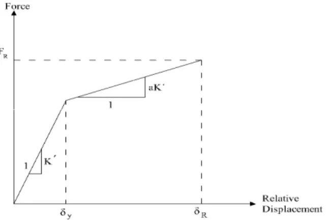
between shear force and relative displacement is concluded (Figure 3). Thus, the ADAS devices bearable forces are given as;
FR=K′δy+aK′(δR−δy), (16)
a = an unknown coefficient to be determined from the experimental data K′ = elastic stiffness of the ADAS devices
δR = maximum relative displacement
δy = yield displacement of the ADAS devices
Figure 3 The relationship between force and relative displacement of ADAS.
The ADAS devices by possessing the stable hysteretic loops resulting from the yielding of steel plates provide reliable energy dissipation.
The ductility ratio µ is defined as;
µ=δR δy
(17)
Let N represent the number of steel plates and K represent the stiffness of a steel plate. Where K′
=N K. Substituting Eq. (16) into Eq. (17) leads to
FR=K′δy+aK′(µδy−δy)=K′δy(1+aµ−a)=KN δy(1+aµ−a) (18)
The stiffness of a steel plate,K can be determined in accordance with the geometric shape of the steel plates; for example,
K= EBT
3
6H3 (Triangular−shape steel plates) (19)
And
K= 2EBT
3
E = elastic modulus of steel B = base width
T = thickness
H = height of the steel plates
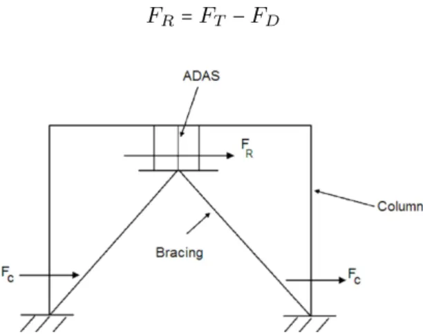
3.2 Seismic forces and the effects of ADAS device design
The bracing members are considered rigid in stiffness during design of a structure with damping devices. The reactive forces due to seismic impact on the building mainly include column shear forces and ADAS-absorbed forces (FC and FR in Fig. 4). The ADAS devices are designed to be able to absorb impact to keep the column shear forces less than the designed column shear forces at any time. Generally, ADAS devices are designed after the Concentric Braced Frames has been designed to meet the seismic building requirements. Let FT be the maximum story shear forces of structures without ADAS devices on each story during earthquakes,FD be the designed column shear forces andFR represent the resistant forces of ADAS dampers that are aimed to be designed. If FT >FD, the goal of using the dampers is to absorbFT−FD so that FC will not exceed FC during the earthquake. The above implies
FR=FT−FD (21)
Figure 4 Shear force distributions of structures with ADAS during earthquakes.
Further, in Eq.(18), we use the designed ductility ratioµd instead of the resulting ductility ratio µ when N plates are used. Eqs. (18) and (21) lead to Eq. (22) to the number of steel plates for the ADAS devices to achieve the above goal:
N = FT−FD KN δy(1+aµd−a)
(22)
4 STUDY ON THE EFFECTS OF THE ENERGY DISSIPATING SYSTEMS
Building Code 97 requirements, based upon the static analysis using following criterias.
1. Soil type is assumed Sc (very dense soil and soft rock) according to UBC97 [23] code.
2. Earthquake source and structures distance from active fault is 10 km according to type A of UBC97.
3. It is assumed that structures are located in zone 4, according to UBC97.
4. The P-Delta effect is included in the analysis.
The Poisson’s ratio, elastic modulus and yield stress for the structure are equal to 0.3 , 2.0 ×10⁶kPa and 2400 Kg/cm2, respectively. The ADAS devices are fabricated on each floor and are supported by chevron bracing. The value of a in Eq. (16) is considered to be 0.12, and the range of the ductility ratios for the ADAS dampers is controlled between 3 and 5 [25].
Table 1 The properties of dampers. Type of the
damper
The geometric properties
h b-top & bottom B middle t ∆y P y K
(cm) (cm) (cm) (cm) (cm) (Kg) (Kg/cm)
ADAS 12.7 6.35 1.27 0.64 0.2794 306 1094
The ADAS devices lower 80 percent of the column shear forces using this procedure when the whole system is subjected to different Earthquake ground movements. Nonlinear time history analysis involves the computation of dynamic response at each time increment con-cerning due consideration given to the inelasticity in members. Hysteretic energy under cyclic loading is evaluated and tabulated. During strong and mediocre earthquakes, structures enter the plastic range. Therefore, it is essential to perform a nonlinear analysis. For this pur-pose, numerical simulations were carried out by PERFORM 3D.V4 [17]. The damping ratio of structures is selected 5%, proportional to mass and stiffness matrix. The plastic hinges in analysis are assumed elastic-perfectly plastic. The non-linear behavior of models is assumed from FEMA273 [2]. Beams and columns are modeled as beam-column elements with a strain hardening of 3%. Bracings are considered as a truss-element that have capability of yielding in tension and buckling in compression and have a strain hardening of 3%. For modeling ADAS an equivalent prismatic beam is used. The mass of structure concentrated in the joints and distributed loads on the beams are applied as fixed end moments on end joints of beams.
4.1 Characteristics of earthquake records used
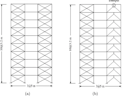
(a) (b)
Figure 5 Type of studied single frame (a) CBF, b) ADAS.
Table 2 Unsealed earthquake records used for non-linear analysis.
Far field
Earthquake Imperial Valley1979/10/15 1994/01/17Northridge 1978/09/15Tabas,Iran
Magnitude M(6.5)Ml(6.6)Ms(6.9) M(6.7)Ml(6.6)Ms(6.7) M(7.4)Ml(7.7)Ms(7.4)
Station 6610 Victoria 900074 La Habra-Briarcliff 69 Bajestan
Data source UNAM/UCSD USD —
PGA 0.122 0.109 0.094
Distance (Km) Closest to fault rapture(54.1) Closest to fault rapture(61.6) Closest to fault rapture(12.12)
Figure 6 Acceleration recorded during Tabas the far field earthquake (PGA = 0.4g).
Figure 7 Acceleration recorded during Northridge far field earthquake (PGA = 0.4g).
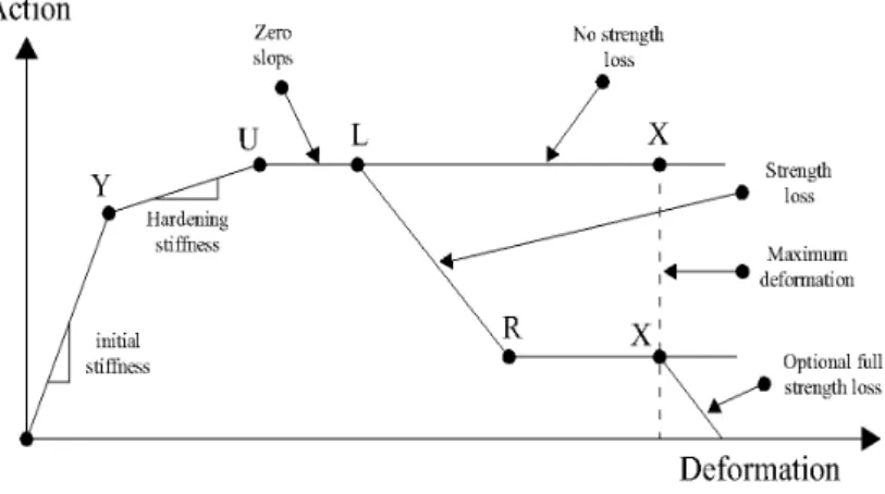
5 BASIC ASSUMPTIONS IN PERFORM 3D 5.1 PERFORM F-D relationship
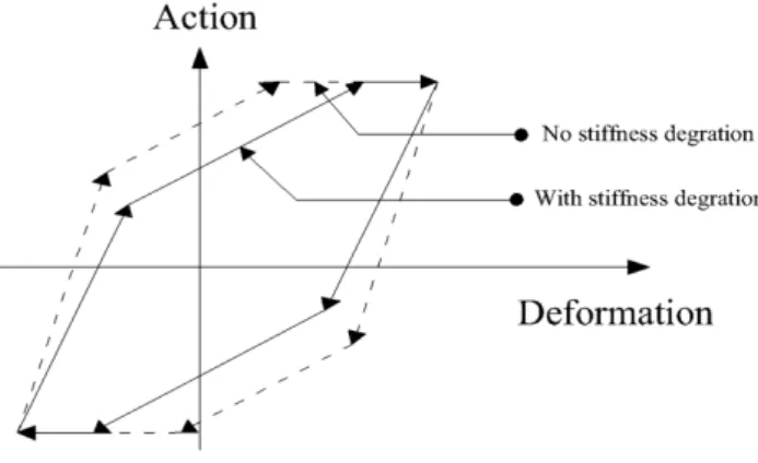
Most of the inelastic components in PERFORM-3D have the same form for the F-D rela-tionship. Figure 9 shows a trilinear relationship with optional strength loss. Strength loss is ignored in non-linear analysis of systems.
Figure 9 PERFORM action-deformation relationship.
There are key points in the relationship; Y point represents the first yield point, where significant nonlinear behavior begins. U point shows the ultimate strength point, where the maximum strength is reached. L point is the ductile limit point, where significant strength loss begins.
R Point is the residual strength point, where the minimum residual strength is reached and the X Point is usually at a deformation that is so large that there is no point in continuing the analysis.
5.2 Hysteresis loops
Two hysteresis loops are shown in Figure 10. In one loop the stiffness degrades and in the other loop it does not. For the degraded loop the amount of energy that is dissipated (the area of the loop) is smaller. The amount of stiffness degradation has the most effect on the amount of energy degradation.
We accounted for the stiffness degradation in the hysteresis loop because the seismic re-sponse of a structure is sensitive to the amount of energy dissipation.
5.3 Dynamic analysis
Figure 10 Hysteresis Loop With Stiffness Degradation.
between the area of the degraded hysteresis loop and the area of the non-degraded loop. For a typical component, this area ratio is 1.0 for small deformation cycles (no degradation) and gets progressively smaller as the maximum deformation increases (increasing degradation).
5.4 Time step
The analysis is performed using step-by-step integration through time, using the constant av-erage acceleration method (also known as the trapezoidal rule or the Newmarkβ = 1
4 method).
We specified the integration time step. The number of steps is the total time divided by the time step, unless the analysis terminates before the end of the earthquake. Since dynamic earthquake analyses can be time consuming, it is natural to want to use as large a time step as possible. A 0.005s time step is used for all non-linear analysis of models.
6 RESULTS AND DISCUSSIONS
6.1 Input energy
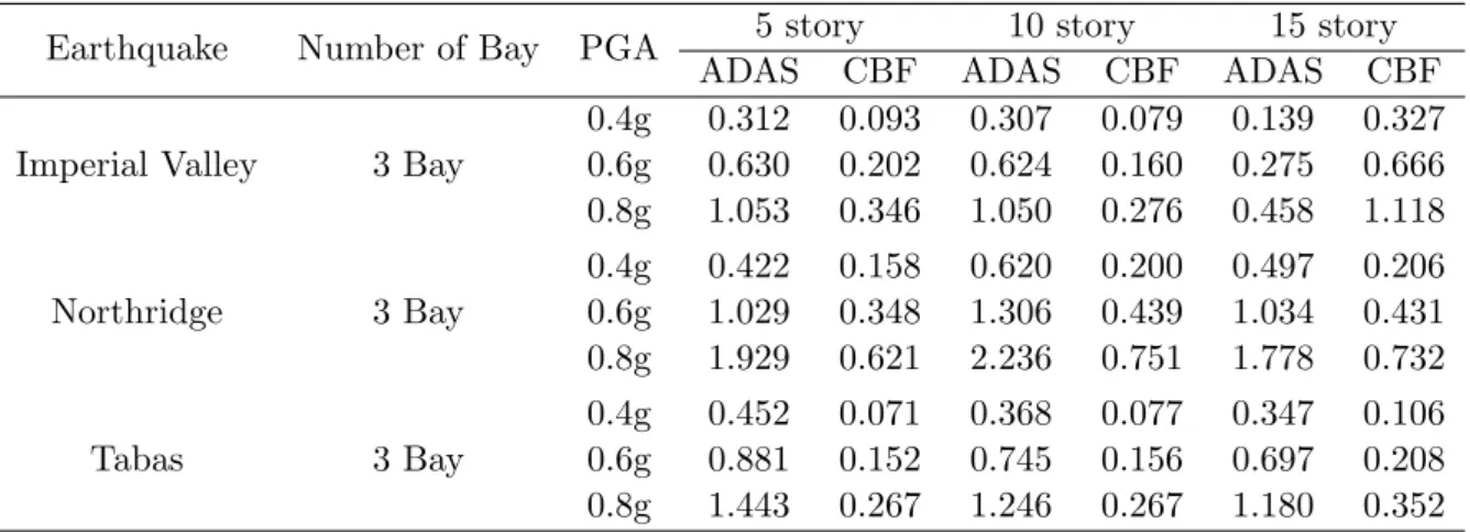
Table 3 The maximum total input energy per mass (m/sec)2in different systems under different earthquakes.
Earthquake Number of Bay PGA 5 story 10 story 15 story ADAS CBF ADAS CBF ADAS CBF
Imperial Valley 3 Bay
0.4g 0.312 0.093 0.307 0.079 0.139 0.327 0.6g 0.630 0.202 0.624 0.160 0.275 0.666 0.8g 1.053 0.346 1.050 0.276 0.458 1.118
Northridge 3 Bay
0.4g 0.422 0.158 0.620 0.200 0.497 0.206 0.6g 1.029 0.348 1.306 0.439 1.034 0.431 0.8g 1.929 0.621 2.236 0.751 1.778 0.732
Tabas 3 Bay
0.4g 0.452 0.071 0.368 0.077 0.347 0.106 0.6g 0.881 0.152 0.745 0.156 0.697 0.208 0.8g 1.443 0.267 1.246 0.267 1.180 0.352
6.2 Hysteretic energy
As previously mentioned about the input energy, hysteretic energy or plastic energy in a structure also is a function of time and for comparing the performance of different systems under earthquake records, the maximum total hysteretic energy at the end of the earthquake is considered.
Table 4 The maximum total hysteretic energy per mass (m/sec)2 in different systems under different
earth-quakes.
Earthquake Number of Bay PGA 5 story 10 story 15 story ADAS CBF ADAS CBF ADAS CBF
Imperial Valley 3 Bay
0.4g 0.166 0.000 0.10 0.00 0.044 0.000 0.6g 0.332 0.006 0.20 0.00 0.131 0.006 0.8g 0.525 0.038 0.32 0.02 0.254 0.048
Northridge 3 Bay
0.4g 0.211 0.012 0.194 0.009 0.115 0.001 0.6g 0.458 0.065 0.379 0.065 0.309 0.017 0.8g 0.760 0.176 0.610 0.183 0.598 0.089
Tabas 3 Bay
0.4g 0.251 0.000 0.116 0.000 0.034 0.000 0.6g 0.479 0.000 0.240 0.000 0.132 0.000 0.8g 0.738 0.005 0.383 0.002 0.278 0.010
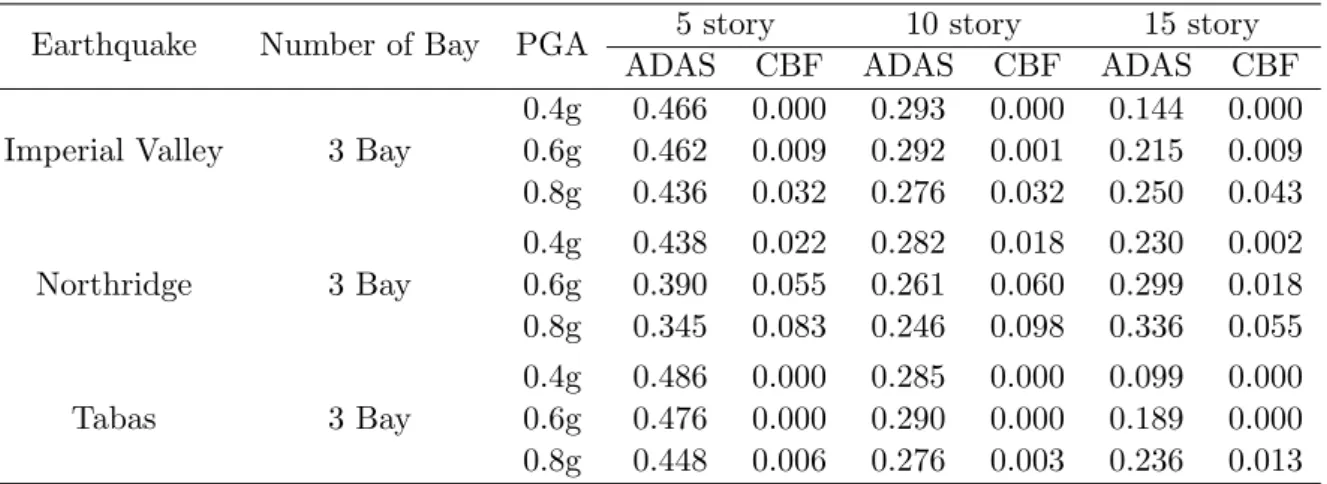
Table 5 The ratio of the hysteretic energy to the input energy in different systems under different earthquakes. Earthquake Number of Bay PGA 5 story 10 story 15 story
ADAS CBF ADAS CBF ADAS CBF
Imperial Valley 3 Bay
0.4g 0.466 0.000 0.293 0.000 0.144 0.000 0.6g 0.462 0.009 0.292 0.001 0.215 0.009 0.8g 0.436 0.032 0.276 0.032 0.250 0.043
Northridge 3 Bay
0.4g 0.438 0.022 0.282 0.018 0.230 0.002 0.6g 0.390 0.055 0.261 0.060 0.299 0.018 0.8g 0.345 0.083 0.246 0.098 0.336 0.055
Tabas 3 Bay
0.4g 0.486 0.000 0.285 0.000 0.099 0.000 0.6g 0.476 0.000 0.290 0.000 0.189 0.000 0.8g 0.448 0.006 0.276 0.003 0.236 0.013
6.3 Effect of increase or decrease in structure height on the ratio of hysteretic energy to input
Height of the structure has the most influence on the shape of maximum total input energy for systems. Also Considering an average diagram with respect to earthquake records and type of systems, yields Figure 14, which shows the effect of height variation on input energy.
Fig. 14 demonstrates the effect of changes in the structure height on the input energy in the ADAS and CBF systems, under the records of the far field. As appear from Figs. 11-13, the input energy in both systems decreases with an increase in height. This decrease is specifically higher in the ADAS system than that in the CBF system, which implies better performance for the ADAS system in tall structures. Moreover, it is evident from this figure that the ratio of hysteretic energy to input in an ADAS system is bigger than that in a CBF one.
Figure 11 Comparison of the (Eh/Ei) ra-tio under Imperial Valley far field record.
Figure 13 Comparison of the (Eh/Ei) ratio under Tabas far field record.
Figure 14 The effect of height of struc-ture on (Eh/Ei) under far field records.
6.4 Effect of PGA variation on the ratio of the hysteretic energy to input energy
Figs. 15-17 depict the impact of variations of maximum acceleration of the earthquake on the ratio of hysteretic energy to input under records of the far field for 5, 10, 15 story buildings under far field records with PGA 0.4g, 0.6g, 0.8g. As it is indicated in the figures the value of the ratio (Eh/Ei) in the steel braced frame equipped with ADAS devices is more than the CBF system. It is considerable that the performance of the ADAS systems is better than the CBF systems. As seen from Figs. 15-17, the hysteretic-to-input ratio is almost constant for the ADAS system with increasing PGA which means nothing but limitation for an ADAS system in absorption of the hysteretic energy in high values of PGA; nonetheless, the value of hysteretic-to-input ratio is much higher in the ADAS system than that in a CBF one.
Figure 15 The relation between the ratio of the hysteretic energy to input energy with PGA under Imperial Valley far field record.
Figure 17 The relation between the ratio of the hysteretic energy to input en-ergy with PGA under Tabas far field record.
Figure 18 The relation between the ratio of the hysteretic energy to input energy with PGA under far field record.
Fig. 18 shows the increasing rate of hysteretic-to-input ratio with respect to increase in PGA and has been plotted for both of these structural systems in the far field. Apparently, according to the figure, Hysteretic-to-input ratio for the ADAS system under records of the far field is not affected by the increase in PGA value, whereas for the CBF, it increases with PGA increase. In fact, this ratio slightly dwindles with height increase in the ADAS system, contrary to the CBF case where it asymptotically rises with PGA increase. Generally, we can conclude that in the records of the far field, performance of the ADAS systems outstrips that of the CBF ones.
7 CONCLUSION
The current study shows the difference of building behaviors with and without damper during earthquake vibrations under the far field records.
1. Having investigated the effect of the building height on the input energy and the plastic energy of the CBF and ADAS systems, we have observed that the vibration behavior of the buildings located in the far field of the fault, based upon the frequency content of the earthquake, depends on the geometric specifications of the building including its height.
2. Increase or decrease in the maximum acceleration does not appear to have much impact on the general form of the comparative graphs of input energy for different systems; as well, PGA increase leads only to a boost in the deviations of the input energy between different systems.
This study implements the commercial package PERFORM 3D.V4, information regarding the seismic hazard, passive control system and nonlinear structural response. The ADAS de-vices significantly increase the resistance of the structure components to the dynamic loads and they are effective in reducing the seismic response of the structures. The benefits of the energy dissipaters have been clearly demonstrated by these comparative data and the improvement in performance of structures during earthquake excitation have been proved. In addition, the considerable effect of the ADAS dampers in absorbing hysteretic energy is illustrated. The passive control system absorbs the vibrations automatically without the need of an electrically controlled system. Passive control systems are generally low in cost and effective for support of buildings subjected to dynamic vibrations. It will allow practicing engineers to design and use cost-effective seismic dampers in the preliminary design phase effectively, letting them explore the cost factors by comparing different building seismic performance objectives throughout design.
References
[1] A. Cruz and O.A. Lopez. Plastic energy dissipated during an earthquake as a function of structural properties and ground motion characteristics. J. Engineering Structures, 22:784–792, 2000.
[2] FEMA 273, NEHRP Guidelines and commentary for the seismic rehabilitation of buildings. Technical Report FEMA 273 (Guidelines), Federal Emergency Management Agency, Washington, D.C., 1997.
[3] E. Fiero, C. Perry, H. Sedarat, and R. Scholl. Seismic retrofit in san francisco using energy dissipation devices.
Earthquake Spectra, Special Issue, 9(3, EERI), 1993. (submitted).
[4] A. Filiatrault and S. Cherry. Seismic design spectra for friction damped structures. Jnl of the Str. Div., ASCE, 116(ST5), 1990.
[5] Seismic isolation and response control for nuclear and non-nuclear structures. In T. Fujita, editor,Special Issue for the Exhibition of 11th Int. Conf. on SMiRT, Tokyo, Japan, 1991.
[6] G.W. Housner, L.A. Bergman, T.K. Caughey, A.G. Chassiakos, R.O. Claus, S.F. Masri, et al. Structural control: Past, present and future. J. Engrg Mech., 123(9):899–905, 1999.
[7] M. A. Iqba and N. K. Gupta. Energy absorption characteristics of aluminum plates subjected to projectile impact.
Latin American Journal of Solids and Structures, 5:259–287, 2008.
[8] C.J. Keel and P. Mahmoodi. Design of viscoelastic dampers for the columbia center building. InBuilding Motion in Wind, New York, 1986. ASCE.
[9] J.M. Kelly, R.I. Skinner, and A.J. Heine. Mechanisms of energy absorption in special devices for use in earthquake-resistant structures. Bull. N.Z. Nat. Soc. for Earthquake Eng., 5(3), 1972.
[10] P. Mahmoodi. Structural dampers. Jnl of the Str. Div., ASCE, 95(ST8), 1969.
[11] P. Mahmoodi, L.E. Robertson, M. Yontar, C. Moy, and L. Feld. Performance of viscoelastic dampers in world trade center towers. In5th ASCE Strs. Cong., Orlando, Florida, 1987.
[12] E. Martinez-Romero. Experiences on the use of supplemental energy dissipators on building structures. Earthquake Spectra, 9(3):581–624, 1993.
[13] A.S. Pall, F. Ghorayeb, and R. Pall. Friction-dampers for rehabilitation of ecole polyvalente at sorel, quebec. In6th Canadian Conf. on Earthquake Eng., Toronto, Canada, 1991.
[14] A.S. Pall and C. Marsh. Seismic response of friction damped braced frames. Jnl of the Str. Div., ASCE, 108(ST6), 1982.
[16] C.L. Perry, E.A. Fierro, H. Sedarat, and R.E. Scholl. Seismic upgrade in san francisco using energy dissipation devices.Earthquake Spectra, 9(3):559–79, 1993.
[17] RAM International, L.L.C., University of California.PERFORM 3D.V4, analysis software.
[18] R.I. Skinner, R.G. Tyler, A.J. Heine, and W.H. Robinson. Hysteretic dampers for the protection of structures from earthquakes.Bull NZ Soc Earthquake Engng, 13(1):22–36, 1980.
[19] M. D. Symans, F. A. Charney, A. S. Whittaker, M. C. Constantinou, C. A. Kircher, M. W. Johnson, and R. J. McNamara. Energy dissipation systems for seismic applications: Current practice and recent developments. J. Struct. Engrg., 134(3-1), 2008.
[20] M. D. Symans and M. C. Constantinou. Semiactive control systems for seismic protection of structures: A state-of-the-art review. J. Engrg. Struct., 21(6):469–487, 1999.
[21] C.S. Tsai, C.S. Chen, B.J. Chen, and W.S. Pong. RADAS device technology for retrofitting damaged structures in 921 Chi-Chi earthquake. InProceedings of ASME, PVP, volume 1, pages 221–8, Vancouver, 2002. Seismic Engineering.
[22] C.-M. Uang and V.V. Bertero. Use of energy as a design criterion in earthquake resistant design. Technical Report UCB/EERC-88/18, Earthquake Eng. Res. Ctr, Univ. of California, Berkeley, 1988.
[23] Uniform building code, 1997.
[24] R. Velmurugan and R. Muralikannan. Energy absorption characteristics of annealed steel tubes of various cross sections in static and dynamic loading. Latin American Journal of Solids and Structures, 6:385–412, 2009.
[25] A.S. Whittaker, V.V. Bertero, C.L. Thompson, and L.J. Alonso. Seismic testing of steel plate energy dissipation devices.Earthquake Spectra, 7(4):563–604, 1991.