This work intends to present a contribution about a proposed approach for the estimative of displacements in reinforced concrete structures sub-mitted to service loads. This work is restrictive to C20 up to C35 classes of strength. The approach used in this work consists in the decreasing of cracking element elastic moduli by damage model. That constitutive model takes into account induced anisotropy, plastic deformations and bi-modular elastic response and a simpliied version is used in order to simulate the concrete behavior, while an elastoplastic behavior is admitted for the reinforcement. Initially, a set of beams are analyzed and some parameters related to the problem are modiied, such as: compression strength, span length, cross section, reinforcement rates and support conditions. The numerical responses are compared with the ones obtained by NBR 6118:2007 Procedure. Statistical analyses are carried on in order to identify the major variables in the problem. Finally, some possible proposals to obtain cracking moment and displacement values in RC structures are discussed based on numerical and statistical analyses performed in this work in order to contribute in the improvement to Brazilian Technical Code procedure.
Keywords: reinforced concrete, technical code, damage mechanics.
Este trabalho visa apresentar uma contribuição sobre uma proposta de abordagem para o cálculo de deslocamentos em estruturas de concre-to armado em regime de serviço, sendo restriconcre-to o estudo ao caso de concreconcre-tos C20 a C35. A abordagem utilizada leva em conta a penalização dos módulos elásticos dos elementos issurados através de um modelo de dano. O modelo em questão leva em conta a anisotropia, deforma -ções plásticas e resposta bimodular induzidas pelo processo de daniicação, sendo uma versão mais simpliicada usada para simular o com -portamento do concreto issurado, enquanto que um com-portamento elastoplástico é admitido para a armadura. Inicialmente, são analisadas séries de vigas com variação de diversos parâmetros relacionados ao problema, tais como: resistência à compressão, arranjo das barras de aço da armadura, dimensões da seção transversal, vão e condições de apoio. As respostas numéricas são confrontadas com aquelas obtidas com o emprego do procedimento sugerido pela NBR 6118:2007. As análises numéricas são complementadas por análises estatísticas dos resultados empregando-se a metodologia ANOVA. Por im, baseadas nas análises realizadas discutem-se algumas proposições possíveis para o cálculo do momento de issuração e de deslocamentos em estruturas de concreto armado, como forma a contribuir no aperfeiçoamento do procedimento sugerido pela Norma Brasileira.
Palavras-chave: concreto armado, norma técnica, mecânica do dano.
Evaluation of delection in reinforced concrete
structures using damage mechanics
Avaliação de delexões em estruturas de concreto
armado utilizando mecânica do dano
J. J. C. Pituba a [email protected]
R. G. DelalibeRa a [email protected]
a Department of Civil Engineering, Federal University of Goiás, Catalão, GO, Brasil.
Abstract
1. Introduction
This paper is a sequence of what is being accomplished aiming at proposing an alternative methodology to the Procedure recom -mended by NBR 6118:2007 [1] for the evaluation of displacements in reinforced concrete structures, [2]. The problem to be solved for the estimative of displacements in reinforced concrete structures using PTV (Principle of Virtual Work), for instance, is not trivial. This is due to the fact that the elements of the reinforced concrete are heterogeneous, composed by concrete and steel, with distinct elasticity modules leading to different stiffness to bending. Further-more, there is the strong possibility of the occurrence of different behaviors in a same structure subjected to loadings of low intensity (service regime), namely, regions where the tensioned concrete presents cracking process (Stage II) and regions where the con-crete is intact (Stage I), not presenting noticeable cracks. Then, the inertia reduction is due to cracking process that contributes for the loss of resistance to the bending movement, where only the reinforcement resists to tension stresses.
In order to propose an alternative methodology, numerical results, obtained from the employment of a damage model [3], associat -ed to comparisons with experimental ones of reinforc-ed concrete structures are used. Therefore, this procedure adopted on this work is an alternative way to the experimental tests which are pensive to be performed. Besides, the use of the numerical and ex-perimental analyses is complimented by statistical analyses based on ANOVA Methodology (Variance Analysis) that it is used to verify the main variables involved in the problem taking into account the numerical and analytical analyses with the use of NBR 6118:2007 Procedure [1].
In [2] has been presented results of the analyses performed in beams with three different spans, transversal sections and reinforce-ment conigurations, however, in that work only the case of concrete with fck=30 MPa and two boundary conditions (simply supported and bi-ixed beams) have been studied. Moreover, numerical analyses in conjunction with statistical ones have led to the determination of expressions for the estimative of the cracking moment (Mcr) depend-ing on the fck used, however such expressions need an investigation with more parameters involved in the problem.
In the present work, such parameters are taken into account in order to obtain expressions for Mcr which deal with called conven-tional concretes of classes C20 to C35. Furthermore, a discussion about the possible propositions of formulas for the evaluation of displacements in reinforced concrete structures is presented in the end of the paper.
The damage model developed by [3] is used in the analyses of reinforced concrete beams submitted to permanent and accidental variable loadings with the changes in the support conditions, span length, compression strength of the concrete, transversal section and reinforcement arrangement. The validation of the numerical responses obtained by the damage model as well as the paramet-ric identiication, can be found in [2], [3] and [4]. The modeling used describes the process of rigidity loss that leads to larger displace-ments, through decreasing of the elasticity module of the material at a certain point of the structure and not in the decreasing of the inertia moment of the studied section and, also, in the representa-tion of this loss by an equivalent inertia in the whole beam, as if the whole beam was homogeneously cracked as it is considered by the NBR 6118:2007 [1]. These issues in conjunction with the reli
-ability of the numerical responses presented by the damage model so far, associated to the low cost of the numerical analyses against the high cost of the experimental ones, have motivated the discus-sion of the problem presented in this work.
In the item 2 of this work is briely presented the models used, such as: damage model, ANOVA and NBR 6118:2007 Procedure. In item 3, the prototypes numerically tested are presented, as well as information about the concretes used in the production of the prototypes. In item 4, the numerical and analytical results are presented and discussions considering ANOVA methodology are developed. Besides, the proposals for the estimative of the crack-ing moment and a discussion about possible approaches for the evaluation of displacements in reinforced concrete structures are presented. Finally, in item 5, the work presents some conclusions.
2. Modeling used
2.1 Damage model
The concrete is assumed as an initially isotropic material that starts to present transverse isotropy and bimodular responses induced by the damage. Moreover, the model tries to respect the principle of energy equivalence between damaged real medium and equiv -alent continuous medium established in the Continuum Damage Mechanics (CDM), [3].
Here in after, the damage model is briely described. So, for the tension dominant states, the following damage tensor is adopted:
(1)
DT
= f
1(D
1, D
4, D
5)
(
A
Ä
A
)
+ 2 f
2(D
4, D
5)
[(
A
Ä
I
+
I
Ä
A
)
-
(
A
Ä
A
)]
where f1(D1, D4, D5) = D1 – 2 f2(D4, D5) and f2(D4, D5) = 1 – (1-D4) (1-D5).
The variable D1 represents the damage in the orthogonal direction to the transverse isotropy local plane of the material, while D4 is representative of the damage generated by the sliding movement between the crack faces. The third damage variable, D5, is only activated if a previous compression state accompanied by damage has occurred.
In the Eq. (1), the tensor I is the second-order identity tensor and the tensor A, by deinition, is formed by the dyadic product of the unit vector perpendicular to the transverse isotropy plane for itself. The tensor product operations between the tensors of second or-der I and A that arise in Eq. (1) and which will be used during all the formulation are described in [3].
For the compression dominant states, the following damage tensor is adopted:
(2)
DC=f
1(D
2,D
4,D
5)
(
A
Ä
A
)
+f
2(D
3)
[(
I
Ä
I
)
-
(
A
Ä
A
)]
+2f
3(D
4,D
5)
[(
A
Ä
I
+
I
Ä
A
)
-
(
A
Ä
A
)]
where f1(D2, D4, D5) = D2 – 2 f3(D4, D5) ,f2(D3) = D3 and f3(D4, D5)= 1 – (1-D4) (1-D5).
and compression cases, assuming for the irst one that there was no previous damage in compression affecting the present tension damage variable D1. Analogously, for the second one it is assumed that has not had previous damage in tension affecting variable D2.
(8)
3
D
2
3
D
D
1 121
-+
-=
)
(
h
;
3
D
2
3
D
D
2 222
-+
-=
)
(
h
Regarding the damage criterion, it is convenient to separate it into two criteria: the irst one is used only to indicate damage incipience when the material is no longer isotropic and the second one is used for loading and unloading when the material is already con-sidered as transverse isotropic.
The criterion for initial activation of the damage processes in ten-sion or compresten-sion is given by:
(9)
f
T,C(
s
) =
* e
W
- Y
0T,0C
< 0
where
W
e∗ is the complementary elastic strain energy
of an isotropic and virgin medium whereas
0 2 T 0 T 0
E
2
Y
=
σ
or0 2 C 0 C 0
E
2
Y
=
σ
is a reference value obtained in uniaxial tension or compression tests, respectively. Theσ
0T eσ
0C parameters are limit elastic stresses.Therefore,
D
0
T
=
(i.e, D1=D4=0) for tension dominant statesor D 0
C= (i.e., D2=D3=D5=0) for compression dominant
states, where the response regime of the material is linear elastic and isotropic.
For the case of g(ε,Dt,DC) > 0, the complementary elastic energy of the damaged medium is given by the relation:
(10)
0 33 22 0 1 0 33 11 22 11 0 0 2 33 2 22 2 1 0 2 11e
(
2
E
)
(
E
1(
D
)
)
E
)
D
1(
E
2
W
-
n
s
s
-s
s
+
s
s
n
-s
+
s
+
-s
=
+ * 2 23 0 0 2 13 2 12 2 5 2 4 0 0E
)
1(
)
(
)
D
1(
)
D
1(
E
)
1(
s
+
s
+
+
n
s
-n
+
+
On the other hand, for compression dominant states (g(ε,D
T,DC) <
0), the complementary elastic energy is expressed by:
(11)
2 3 0 33 22 0 3 2 0 33 11 22 11 0 2 3 0 2 33 2 22 2 2 0 2 11 e)
D
1(
E
)
D
1)(
D
1(
E
)
(
)
D
1(
E2
)
(
)
D
1(
E2
W
-s
s
n
-s
s
+
s
s
n
-s
+
s
+
-s
=
-* 2 23 0 0 2 13 2 12 2 5 2 4 0 0E
)
1(
)
(
)
D
1(
)
D
1(
E
)
1(
s
+
s
+
+
n
s
-n
+
+
D2 (damage perpendicular to the transverse isotropy local plane of the material) reduces the Young’s modulus in that direction. On the other hand, the variable D2 together with D3 (that represents the damage in the transverse isotropy plane) degrades the Poisson’s ratio on the perpendicular planes to the one of transverse isotropy. Finally, the resultant constitutive tensors ET and EC may be de-scribed as follow:
(3)
=
TE
l
11[
I
Ä
I
]
+
2
m
1[
I
Ä
I
]
-
l
+22(
D
1,
D
4,
D
5)
[
A
Ä
A
]
)
(
1 12l
+D
-
[
A
Ä
I
+
I
Ä
A
]
-
m
2(
D
4,
D
5)
[
A
Ä
I
+
I
Ä
A
]
(4)
=
C
E
l
11[
I
Ä
I
]
+
m2
1[
I
Ä
I
]
-
l
-22(
D
2,
D
3,
D
4,
D
5)
[
AÄ
A
]
-
l
12-(
D
2,
D
3)
[A
Ä
I+I
Ä
A]
)
(
3 11l
-D
-
[
I
Ä
I
] -
(
)
11(
3)
0 0
l
n
n2
1
-
-D
[
I
Ä
I
]
(
,
)
5 4 2
m
D
D
-
[
A
Ä
I
+
I
Ä
A
]
where
λ =
11λ
0 andµ =
1µ
0. The remaining parameters willonly exist for no-null damage, evidencing in that way the anisot-ropy and bimodularity induced by damage. Those parameters are given by:
(5)
)
,
(
)
(
)
)(
(
)
,
,
(
2 12 1 2 4 51 1 0 0 5 4 1
22
l
2
m
2
l2
2
m
l
+D
D
D
=
+
D
-
D
-
+D
-
D
D
1 0 1
12
l
l
+(
D
)
=
D
;
(
,
)
[
(
)
(
)
2]
5 2 4 0 5 4
2
2
m
1
1
1
m
D
D
=
-
-
D
-
D
)
,
(
)
(
)
(
5 4 2 3 11 00
l
2
m
n
1
n
D
D
D
-+
-)]
)(
(
)
[(
)
,
(
2 3 0 3 2 2 312
l
1
1
1
l
-D
D
=
-
D
-
-
D
-
D
)
(
)
(
3 0 3 2311
l
2
l
-D
=
D
-
D
;
m
2(
D
4,
D
5)
=
2
m
0[
1
-
(
1
-
D
4)
2(
1
-
D
5)
2]
In [3], a hypersurface is deined either in the stress or strain space in order to identify the bimodular constitutive response to be used. A particular form is adopted for the hypersurface in the strain space: a hyperplane g(ε) deined by the unit normal N (||N|| = 1) and characterized by its dependence of the strain and damage states. Therefore, the following relation is proposed:
(6)
g(
e
,DT,DC) = N(DT,DC) .
e
e=
g
1(D1,D2)e V
e
+
g
2(D1,D2) e 11e
where γ1(D1,D2)={1+H(D2)[H(D1)-1]}η(D1)+{1+H(D1)[H(D2)-1]}η(D2) and γ2(D1,D2) = D1+D2.
The Heaviside functions employed above are given by:
(7)
H(D
i) = 1 for D
i> 0;H(D
i) = 0 for D
i= 0 (i = 1, 2)
(15)
22 2
1 0
T
E
1
D
1
D
E
=
(
-
)
(
-
)
(16)
2 2 0
C
E
1
D
E
=
(
-
)
(17)
22 2 1 0
2 11 e
2
E
1
D
1
D
W
)
(
)
(
-
-=
+*
s
;
22 0
2 11 e
2
E
1
D
W
)
(
-=
-*
s
(18)
YT =
=
* +1 e
D
W
Y1; YC
=
=
*
-2 e
D
W
Y2
(19)
2 2 3 1 0
2 11
1
E
1
D
1
D
Y
)
(
)
(
-
-=
s
;
32 0
2 11
2
E
1
D
Y
)
(
-=
s
2.2 NBR6118:2007 Procedure
The evaluation models of displacements in reinforced concrete beams consider the behavior of the structural elements subjected to bending moment in the Stage I (intact section without crack, considering the tension stress in the concrete) and Stage II (sec-tion with cracks, the contribu(sec-tion of the concrete submitted to ten-sion stress is not considered for the equilibrium of the transversal section).
The NBR 6118:2007 [1] presents a criterion for the estimative of the excessive displacement in concrete beams subject a bend -ing moment, based in weight procedure of the inertia moments of Stages I (I1) and II (I2), resulting in equivalent inertia moment, Ieq. This equivalent inertia moment is calculated by Eq. (20). Such procedure is valid since the acting moment in the critical section, Ma, is higher than the bending moment that initiates the cracking process, Mr.
(20)
c
I
I
M
M
1
I
M
M
I
23
a r c
3
a r
eq
×
£
ú
ú
û
ù
ê
ê
ë
é
÷÷ø
ö
ççè
æ
-+
×
÷÷ø
ö
ççè
æ
=
In Eq. (20), Ic, is the inertia moment of the intact section, without consideration of the reinforcement bars in the transversal section (section homogenization).
The cracking moment, Mr , is calculated by the Eq. (21). It can be ob -Considering a general situation of the damaged medium in tension
dominant regime, the criterion for the identiication of damage evo -lution is represented by the following relation:
(12)
0
Y
W
f
T(
s
)
=
e*+-
0*T£
where the reference value
Y
0∗T is deined by the maximum comple -mentary elastic energy determined during the damage process un-til the actual state. For the damaged medium in compression domi-nant regime, analogue relations are valid to the case of tension. In the loading case, i.e., when or , one needs to update the values of the scalar damage variables that appear in the Dt and DC ten-sors, considering their evolution laws.In the numerical applications presented in this work, the monotonic loading is considered. The evolution laws for the scalar damage variables have been proposed according to the experimental re-sults. Thus, the general form proposed is
(13)
[
(
)
]
exp
i i 0ii
i
i
1
A
1
B
A
Y
Y
D
=
-
+
+
-
com i = 1, 2
where Ai, Bi and Y0i are parameters that must be identiied. The parameters Y0i are understood as initial limits for the damage ac-tivation, Eq. (9).
When the damage process is activated, the formulation starts to involve the tensor A that depends on the knowledge of the normal to the transverse isotropy plane. Therefore, it is necessary to es-tablish some rules to identify its location for an actual strain state. Therefore, the following assert is assumed as valid: “ In the prin -cipal strain space, if two of the three strain rates are extension, shortening or null, the plane deined by them will be the transverse isotropy local plane of the material.”
For this work is interesting observe that the uniaxial tension is an example of the case above where the transverse isotropy plane is perpendicular to the tension stress direction. The same observa-tion is valid for uniaxial compression case.
The one-dimensional version of the damage model has been implemented in a program for bars structures analysis with fi-nite layered elements. The damage mode previously described is assumed to govern the concrete layers behavior and for the longitudinal reinforcement bars, an elastoplastic behavior is admitted. In the transversal section, a certain layer can con-tain steel and concrete. It is defined, for each layer, an elastic modulus and an inelastic strain equivalent, by using homog -enization rule.
On the other hand, adopting direction 1 as longitudinal bar direc-tion, the relations of the models in its one-dimensional version are summarized as follows:
(14)
î
í
ì
=
T C
E
E
E
:
se
se
,
)
,
,
(
,
)
,
,
(
0
D
D
g
0
D
D
g
C T
C T
>
<
e
e
served in Eq. (21) that the Brazilian Code do not consider the favorable effect of the reinforcement bars, decreasing, therefore, the value of Mr.
(21)
t c ct r
α
f
y
I
M
=
×
×
The value of α used in Eq. (21) is equal to 1.2 for transversal sec -tions T or double T and it is equal to 1.5 for rectangular transversal section. The tension strength of the concrete (fct) is calculated by Eq. (22), and yt, is the distance from the gravity center of the transversal section to the most tensioned iber of the transversal section.
(22)
3 2 ck ct
0,21
f
f
=
×
where fck is the compression strength of the concrete.
However, the bending moment on the critical section, Ma, is deter-mined by an quasi-permanent combination of loads. This combi -nation reduces the intensity of the live loads, through a statistical coeficient Ψ2, which value can be equal to 0,3, 0,4 and 0,6, de -pending for what purpose is designed the use of the structure. The almost-permanent condition is calculated by Eq. (23).
(23)
å
å
=
+
=×
=
n1 i
m
1
i 2j qj,k k,
gi
F
F
ψ
F
d,serIn Eq. (23), Fg represents the values of the intensities of the dead load and Fq represents the values of the intensities of the variables live loads.
Having considered the beam equivalent stiffness that represents an average behavior of the whole beam, it can proceed to the esti-mative of the immediate delection δ by means of the equations of Materials Strength which are valid for constant sections along the structural element, i.e.:
(24)
( )
eq 4 cEI
pl
a
=
d
where:
n αc is a coeficient which depends on the boundary conditions of the beam and on the kind of acting loads;
n p is the load applied;
n l is the span length of the beam.
n (EI)eq is the equivalent stiffness of the cracked beam given by the Elasticity Modulus of the concrete and the inertia moment in the Stage II (eq. (20)).
2.3 ANOVA Methodology
The Variance Analysis (ANOVA) is a statistic test used by analysts, and seeks fundamentally to verify if there is a meaningful differ-ence between the averages and if the factors carry inludiffer-ence in some dependent variable, [5].
The factors proposed can be of qualitative or quantitative origin, but the dependent variable necessarily must be continuous. The
main application of ANOVA is the comparison between averages coming from different groups, also called treatments.
There are two types of problems to be solved by ANOVA: ixed fac -tors or random fac-tors. The randomness determines the question of the problem. In most cases, it deals with ixed factors; after all, the second type of problem (random) will only arise when there is a study involving a random choice of factors.
In the variance analysis developed in this work, ixed factors have been used and it has been chosen ive study variables: compres -sive strength of the concrete; boundary conditions; transversal section; the effective span length; the quantity of steel bars of the longitudinal reinforcement. The chosen variables reached one hundred eight cases of combinations, they are: span length, steel area, inertia moment and correlations between span length and steel area, span length and inertia moment and, inally, steel area and inertia moment. Further information of the methodology devel-oped can be seen in [2].
3. Test models
The one-dimensional version of the damage model has been implemented in a program for bars structures analysis with inite layered elements. For calculus purposes, the weight of the beams has been taken into account in the inite element models as per -manent loading.
Now, the inite element models of the beams used in order to verify the inluence of some parameters in the estimative of displace -ments are described. In this work, these models are called “test prototypes”, and they have been used in the numerical analyses in order to compare with analytical responses given by the NBR Procedure [1].
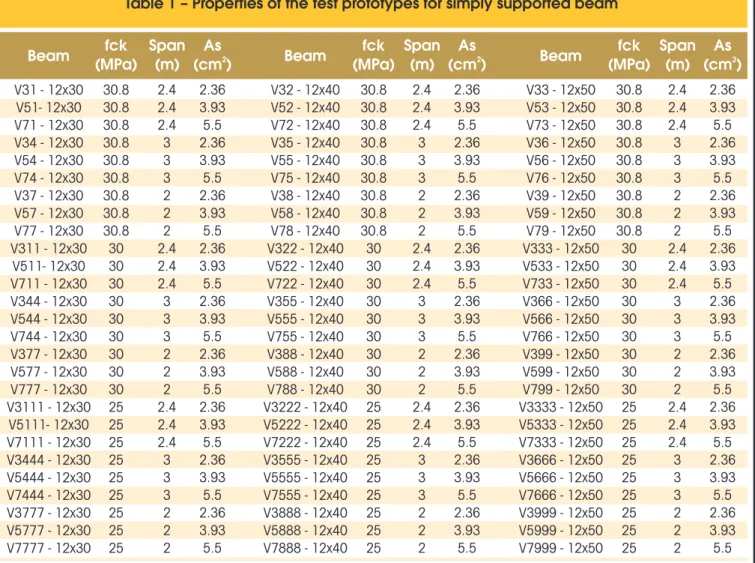
In this work, some parameters involved in the problem have been changed, such as: effective span length, height of the cross sec -tion, reinforcement distribu-tion, compression strength of the con-crete and the boundary conditions. Therefore, the testing models set add up a total of 324 cases, where there are three types of concretes, three types of reinforcement distribution, three different span lengths, three different heights of the transversal section and four types of boundary conditions, beyond the possible combina-tions of these cases.. The inite element models are named accord -ing to the properties contained in the Table 1 and their geometries are described in the Fig. 1. It is important to note that the Fig. 1 can represent the boundary conditions as simply supported, ixed and simply supported, bi-ixed, ixed and free ends (cantilever beam). In order to check the vertical displacement obtained by numerical analyses presented in this work, it has been calculated analyti-cally the vertical displacements of the RC beams submitted to the action of bending moment, using the criteria suggested by NBR Procedure [1], where it has been considered as permanent loads the weight of the beams and as accidental variable loads, the force
Table 1 – Properties of the test prototypes for simply supported beam
Beam
(MPa)
fck
Span
(m)
(cm )
As
2Beam
(MPa)
fck
Span
(m)
(cm )
As
2Beam
(MPa)
fck
Span
(m)
(cm )
As
2V31 - 12x30
V51- 12x30
V71 - 12x30
V34 - 12x30
V54 - 12x30
V74 - 12x30
V37 - 12x30
V57 - 12x30
V77 - 12x30
V311 - 12x30
V511- 12x30
V711 - 12x30
V344 - 12x30
V544 - 12x30
V744 - 12x30
V377 - 12x30
V577 - 12x30
V777 - 12x30
V3111 - 12x30
V5111- 12x30
V7111 - 12x30
V3444 - 12x30
V5444 - 12x30
V7444 - 12x30
V3777 - 12x30
V5777 - 12x30
V7777 - 12x30
V32 - 12x40
V52 - 12x40
V72 - 12x40
V35 - 12x40
V55 - 12x40
V75 - 12x40
V38 - 12x40
V58 - 12x40
V78 - 12x40
V322 - 12x40
V522 - 12x40
V722 - 12x40
V355 - 12x40
V555 - 12x40
V755 - 12x40
V388 - 12x40
V588 - 12x40
V788 - 12x40
V3222 - 12x40
V5222 - 12x40
V7222 - 12x40
V3555 - 12x40
V5555 - 12x40
V7555 - 12x40
V3888 - 12x40
V5888 - 12x40
V7888 - 12x40
V33 - 12x50
V53 - 12x50
V73 - 12x50
V36 - 12x50
V56 - 12x50
V76 - 12x50
V39 - 12x50
V59 - 12x50
V79 - 12x50
V333 - 12x50
V533 - 12x50
V733 - 12x50
V366 - 12x50
V566 - 12x50
V766 - 12x50
V399 - 12x50
V599 - 12x50
V799 - 12x50
V3333 - 12x50
V5333 - 12x50
V7333 - 12x50
V3666 - 12x50
V5666 - 12x50
V7666 - 12x50
V3999 - 12x50
V5999 - 12x50
V7999 - 12x50
30.8
30.8
30.8
30.8
30.8
30.8
30.8
30.8
30.8
30
30
30
30
30
30
30
30
30
25
25
25
25
25
25
25
25
25
30.8
30.8
30.8
30.8
30.8
30.8
30.8
30.8
30.8
30
30
30
30
30
30
30
30
30
25
25
25
25
25
25
25
25
25
30.8
30.8
30.8
30.8
30.8
30.8
30.8
30.8
30.8
30
30
30
30
30
30
30
30
30
25
25
25
25
25
25
25
25
25
2.4
2.4
2.4
3
3
3
2
2
2
2.4
2.4
2.4
3
3
3
2
2
2
2.4
2.4
2.4
3
3
3
2
2
2
2.4
2.4
2.4
3
3
3
2
2
2
2.4
2.4
2.4
3
3
3
2
2
2
2.4
2.4
2.4
3
3
3
2
2
2
2.4
2.4
2.4
3
3
3
2
2
2
2.4
2.4
2.4
3
3
3
2
2
2
2.4
2.4
2.4
3
3
3
2
2
2
2.36
3.93
5.5
2.36
3.93
5.5
2.36
3.93
5.5
2.36
3.93
5.5
2.36
3.93
5.5
2.36
3.93
5.5
2.36
3.93
5.5
2.36
3.93
5.5
2.36
3.93
5.5
2.36
3.93
5.5
2.36
3.93
5.5
2.36
3.93
5.5
2.36
3.93
5.5
2.36
3.93
5.5
2.36
3.93
5.5
2.36
3.93
5.5
2.36
3.93
5.5
2.36
3.93
5.5
2.36
3.93
5.5
2.36
3.93
5.5
2.36
3.93
5.5
2.36
3.93
5.5
2.36
3.93
5.5
2.36
3.93
5.5
2.36
3.93
5.5
2.36
3.93
5.5
2.36
3.93
5.5
Note: In case of bi-fixed beams are added the letters be at the end of the name, as well as ea to fixed-supported and e to
values of the Fr and 3Fr, applied to the l/3 distances and 2l/3 from the support of the left of the beam (see Fig. 1). The force Fr has been obtained by Eq. (25) and its value depends on the cracking moment value (Eq. 21).
(25)
2
8
g
M
F
r r 2÷÷ø
×
ö
ççè
æ
-
×
=
In Eq. (25), Fr is the value of the force intensity that composes the cracking process, g represents the weight of the reinforced con-crete beam and l is the span length of the beam.
Note that, the parametric identiication of the damage model for the concretes with compression strength of 25MPa, 30 MPa and 30,8 MPa used in this work is presented in [2] and [4], as well as the employment of the damage model in the numerical analyses of RC beams and frames is presented in [6], [7] and [8]. Those results are compared with experimental ones in order to validate the employment of the damage model. The parameters are presented in Table 2.
Table 2 – Parameters of the damage model for the concretes used in this work
Concrete fck = 25.0 MPa
Concrete fck = 30.8 MPa
Concrete fck = 30.0 MPa
Tension
Compression
Tension
Compression
Tension
Compression
Y / Y (MPa)
01 02A / A
1 2 -1B /B (MPa )
1 2-4
1.137x10
A = 5.33
1B = 5660
1-4
Y = 0.72x10
01A = 50
1B = 6700
1-4
Y = 0.72x10
01A = 50
1B = 6700
1 -5Y =0.5x10
02A = -0.0086
2B = 5.71
2-3
Y =0.5x10
02A = -0.9
2B = 0.4
2-3
Y =1.7x10
02A = -0.8
2B = 1.1
2Table 3 – Displacement values obtained by the NBR 6118:2007
Procedure and numerical tests for Fr. (cantilever beam, 30.8 MPa)
Beam
Fr NBR (KN)
Fr Num (KN)
Disp. NBR (cm)
Disp. Num (cm)
Difference (%)
P = Fr
V31e- 12x30
V51e- 12x30
V71e - 12x30
V34e - 12x30
V54e - 12x30
V74e - 12x30
V37e - 12x30
V57e - 12x30
V77e - 12x30
V32e - 12x40
V52e - 12x40
V72e- 12x40
V35e - 12x40
V55e - 12x40
V75e - 12x40
V38e - 12x40
V58e - 12x40
V78e - 12x40
V33e - 12x50
V53e - 12x50
V73e - 12x50
V36e - 12x50
V56e - 12x50
V76e - 12x50
V39e - 12x50
V59e - 12x50
V79e - 12x50
2.24
2.24
2.24
1.30
1.30
1.30
3.08
3.08
3.08
4.46
4.46
4.46
2.92
2.92
2.92
5.87
5.87
5.87
7.41
7.41
7.41
5.12
5.12
5.12
9.55
9.55
9.55
1.84
1.88
1.90
1.51
1.50
1.51
2.22
2.28
2.30
3.27
3.31
3.36
2.60
2.60
2.52
3.87
3.82
3.87
5.02
5.12
5.21
4.01
3.94
4.00
5.76
5.90
6.00
0.20
0.20
0.20
0.29
0.29
0.29
0.14
0.14
0.14
0.15
0.15
0.15
0.23
0.23
0.23
0.11
0.11
0.11
0.12
0.12
0.12
0.19
0.19
0.19
0.09
0.09
0.09
0.105
0.105
0.105
0.170
0.162
0.162
0.080
0.080
0.080
0.083
0.082
0.082
0.127
0.124
0.119
0.060
0.060
0.060
0.067
0.069
0.069
0.110
0.101
0.101
0.050
0.050
0.050
According with experimental data reported in [6], the irst concrete has tension strength of 2.3 MPa and elasticity modulus of 32,300 MPa. The second concrete has tension strength of 2.25 MPa and elasticity modulus of 29,200 MPa, [8]. The third one, according with [7], has 30,400 MPa for the elasticity modulus. The steel used in the reinforcement has Es = 196,000 MPa and yielding stress of 500 MPa. It is important to note that the inite element models have been tested in order to obtain the objectivity of the meshes used here, [2] and [4]. Therefore, in the numerical analyses the geometry symmetries has been taken into account and only half beam has been analyzed. The longitudinal discretization has been composed by 16 inite elements whereas for the cross section, 15 layers representing concrete and/or steel have been employed.
4. Numerical, analytical
and statistical results
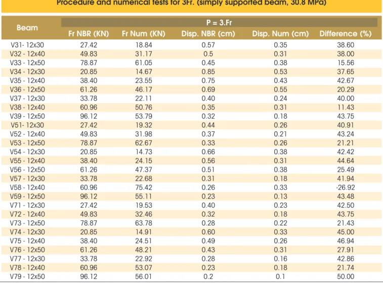
Due to the high number of results, in the following tables are de-scribed some of them. The results consist in vertical displacements in the middle of the span of each test prototype obtained by the employment of the NBR 6118:2007 Procedure [1], as well as those
obtained in the numerical analyses. The values P=Fr and P=3Fr have been considered in order to analyze the behavior of the NBR 6118:2007 [1] Procedure related to the evolution of the damage process on the beams.
The percentage values of the difference between the results have been calculated adopting the ones recommended by NBR 6118:2007 [1]as reference values.
It can be observed on the tables above the conservatism of the calculation procedure of NBR 6118:2007 [1], being relected, in most cases, in differences about 30% to 50%. In the case of bi-ixed beams, the difference becomes more relevant (Table (4)). In general, it can even be observed that the differences between the displacement values decrease with the increase of the applied load Fr. The model adopted by NBR6118:2007 [1] approaches the beam stiffness using just only one value to whole beam leading to high displacement values. Otherwise, the damage model degrades selectively the longitudinal elasticity modulus of each concrete lay-er in each inite element along beam giving a more realistic simula -tion of the damage process on the beam, which usually results in smaller displacements than those obtained with NBR6118:2007 [1] analytical model. It can be observed that the tensioned concrete
Table 4 – Displacement values obtained by the NBR 6118:2007
Procedure and numerical tests for Fr. (bi-fixed beam, 30.0 MPa)
Beam
Fr NBR (KN)
Fr Num (KN)
Disp. NBR (cm)
Disp. Num (cm)
Difference (%)
P = Fr
V311be- 12x30
V511be- 12x30
V711be - 12x30
V344be - 12x30
V544be - 12x30
V744be - 12x30
V377be - 12x30
V577be - 12x30
V777be - 12x30
V322be - 12x40
V522be - 12x40
V722be- 12x40
V355be - 12x40
V555be - 12x40
V755be - 12x40
V388be - 12x40
V588be - 12x40
V788be - 12x40
V333be - 12x50
V533be - 12x50
V733be - 12x50
V366be - 12x50
V566be - 12x50
V766be - 12x50
V399be - 12x50
V599be - 12x50
V799be - 12x50
13.85
13.85
13.85
10.72
10.72
10.72
16.92
16.92
16.92
24.99
24.99
24.99
19.50
19.50
19.50
30.38
30.38
30.38
39.38
39.38
39.38
30.9
30.9
30.9
47.75
47.75
47.75
12.06
12.33
12.44
11.47
11.71
11.80
19.02
19.18
15.53
28.04
28.50
28.63
15.98
16.36
16.58
27.37
27.56
27.41
36.54
36.66
36.63
32.07
32.73
33.18
47.14
47.57
47.73
0.10
0.10
0.10
0.15
0.15
0.15
0.07
0.07
0.07
0.07
0.07
0.07
0.11
0.11
0.11
0.05
0.05
0.05
0.06
0.06
0.06
0.09
0.09
0.09
0.04
0.04
0.04
0.018
0.018
0.018
0.032
0.032
0.032
0.017
0.017
0.014
0.020
0.020
0.020
0.034
0.022
0.022
0.017
0.011
0.017
0.022
0.022
0.022
0.025
0.025
0.025
0.017
0.017
0.017
between cracks is taken into account in the resistance to the bend-ing moment accordbend-ing to the damage model, such fact does not happen in the formulation of the model used by NBR6118:2007 [1]. It can also be observed that NBR6118:2007 [1] provides one only value of Mr regardless the reinforcement arrangement disposed in the beam. However, the numerical analyses show a variation in Mr value, which would be more natural because the mechanical behavior of the beam will obviously be inluenced by the reinforce
-ment arrange-ment from the beginning of the cracking process to its collapse, among other factors, [2].
In [2] are presented the statistical analyses performed with ANO -VA methodology for the case of the simply supported and bi-ixed beams with the variation of parameters already mentioned in the introduction of this work. Then, in [2] has been observed that the transversal section and span length are the most important vari-ables in the problem when the beam is subjected to moderate val
-Table 5 – Displacement values obtained by the NBR 6118:2007
Procedure and numerical tests for 3Fr. (simply supported beam, 30.8 MPa)
Beam
Fr NBR (KN)
Fr Num (KN)
Disp. NBR (cm)
Disp. Num (cm)
Difference (%)
P = 3.Fr
V31- 12x30
V32 - 12x40
V33 - 12x50
V34 - 12x30
V35 - 12x40
V36 - 12x50
V37 - 12x30
V38 - 12x40
V39 - 12x50
V51- 12x30
V52 - 12x40
V53 - 12x50
V54 - 12x30
V55 - 12x40
V56 - 12x50
V57 - 12x30
V58 - 12x40
V59 - 12x50
V71 - 12x30
V72 - 12x40
V73 - 12x50
V74 - 12x30
V75 - 12x40
V76 - 12x50
V77 - 12x30
V78 - 12x40
V79 - 12x50
27.42
49.83
78.87
20.85
38.40
61.26
33.78
60.96
96.12
27.42
49.83
78.87
20.85
38.40
61.26
33.78
60.96
96.12
27.42
49.83
78.87
20.85
38.40
61.26
33.78
60.96
96.12
18.84
31.17
61.05
14.67
23.55
46.17
22.11
50.76
53.79
19.32
31.98
62.67
14.73
24.15
47.37
22.68
75.42
55.11
19.53
32.46
63.78
14.91
24.51
48.21
22.92
53.07
56.01
0.57
0.5
0.45
0.85
0.75
0.69
0.40
0.35
0.32
0.44
0.37
0.33
0.66
0.56
0.51
0.31
0.26
0.23
0.40
0.32
0.28
0.60
0.49
0.43
0.28
0.23
0.2
0.35
0.31
0.38
0.53
0.43
0.55
0.24
0.31
0.18
0.26
0.21
0.26
0.38
0.31
0.38
0.18
0.33
0.13
0.23
0.18
0.22
0.33
0.26
0.31
0.16
0.18
0.1
38.60
38.00
15.56
37.65
42.67
20.29
40.00
11.43
43.75
40.91
43.24
21.21
42.42
44.64
25.49
41.94
-26.92
43.48
42.50
43.75
21.43
45.00
46.94
27.91
42.86
21.74
50.00
Table 6 – Simply supported beam, fck=25 MPa, analytical values, F = Fr
Simply supported beam C25 F=F Analytical
RUltimate force
Factors
Squares sum
Freedom degrees
Squares average
F
0F
critical, 0.5N=26
ℓ
A
sA
cℓ X A
sℓ
X A
cA X A
s cError
Total
-3
8.6 x 10
0
-34.2 x 10
0
-44 x 10
0
0
0.0013
-3
4.3 x 10
0
-32.1 x 10
0
-510 x 10
0
0
–
-3
4.3 x 10
0
-32.1 x 10
0
-510 x 10
ues of the service loads. However, when the loading value increas-es, the transversal section keeps the most important variable, but the reinforcement distribution becomes a more important variable than the span length. This change is due to the very intense dam-age process which occurs in the beam in this loading stdam-age. In this work, some additional parameters are introduced, such as: one more concrete with compression strength of 25 MPa and two new boundary conditions (cantilever beam and ixed and simply supported beam). Moreover, in order to overcome a gap left in the
work [2], the change of span length from 4 m to 2 m has been made. The, now, the cantilever beam cases have analytical and numerical possible results, in order to contribute for the statistical analyses. Once again, it is necessary the presentation of some tables with statistical results referring to concrete C25 in simply supported beams, as example. In fact, the analyses lead to the making of 48 tables.
Closing, it is related here that the results of the statistical analyses do not show any evident change of the behavior of the problem
Table 7 – Simply supported beam, fck=25 MPa, numerical values, F = Fr
Simply supported beam C25 F=F Analytical
RUltimate force
Factors
Squares sum
Freedom degrees
Squares average
F0
F
critical, 0.5N=26
ℓ
A
sA
cℓ
X A
sℓ
X A
cA X A
s cError
Total
-3
1.064 x 10
-5
3.5 x 10
-3
1.026 x 10
-4
3.653 x 10
-4
7.06 x 10
-4
2.693 x 10
-4
5.307 x 10
-3
3.996 x 10
-4
5.32 x 10
-5
1.733 x 10
-4
5.13 x 10
-5
9.133 x 10
-4
1.765 x 10
-5
6.733 x 10
-5
6.633 x 10
–
8.02
0.261
7.734
1.377
1.015
2.661
–
–
3.37
3.37
3.37
2.74
2.74
2.74
–
–
2
2
2
4
4
4
8
26
Table 8 – Simply supported beam, fck=25 MPa, analytical values, F = 3 Fr
Simply supported beam C25 F=3F Analytical
RUltimate force
Factors
Squares sum
Freedom degrees
Squares average
F
0F
critical, 0.5N=26
ℓ
A
sA
cℓ
X A
sℓ
X A
cA X A
s cError
Total
0.391
0.123267
0.051
0.011
-3
4.489 x 10
-4
1.778 x 10
-4
1.111 x 10
0.581
0.195
0.062
0.026
-3
2.694 x 10
-3
1.122 x 10
-5
4.444 x 10
-5
1.389 x 10
–
4
1.407 x 10
3
4.438 x 10
3
1.854 x 10
194
3.2
80.8
–
–
3.37
3.37
3.37
2.74
2.74
2.74
–
–
2
2
2
4
4
4
8
26
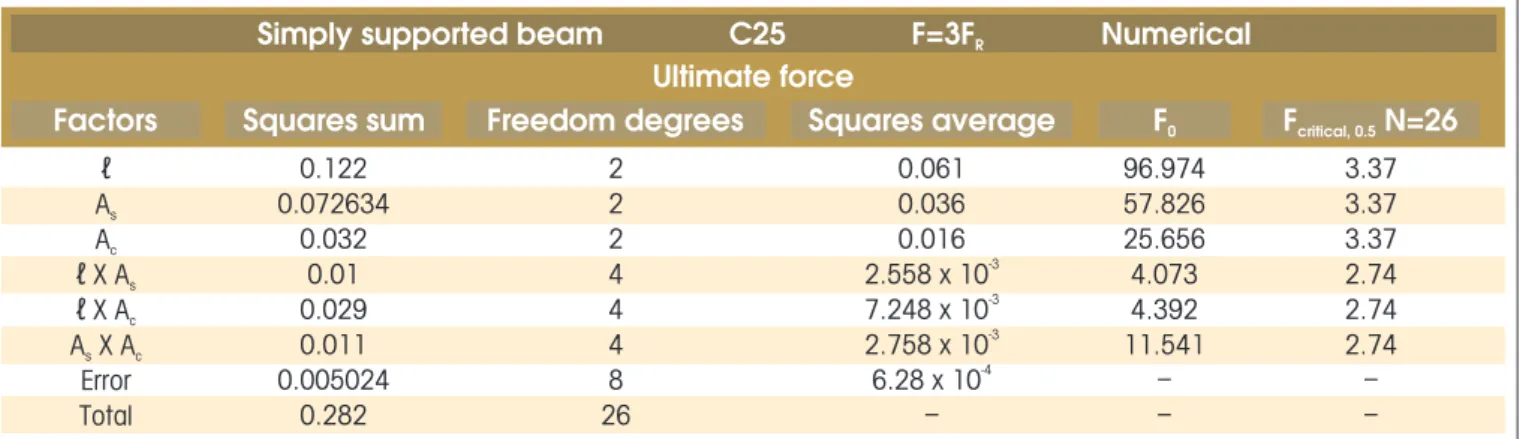
Table 9 – Simply supported beam, fck=25 MPa, numerical values, F = 3Fr
Simply supported beam C25 F=3F Numerical
RUltimate force
Factors
Squares sum
Freedom degrees
Squares average
F
0F
critical, 0.5N=26
ℓ
A
sA
cℓ X A
sℓ
X A
cA X A
s cError
Total
0.122
0.072634
0.032
0.01
0.029
0.011
0.005024
0.282
0.061
0.036
0.016
-3
2.558 x 10
-3
7.248 x 10
-3
2.758 x 10
-4
6.28 x 10
–
96.974
57.826
25.656
4.073
4.392
11.541
–
–
3.37
3.37
3.37
2.74
2.74
2.74
–
–
2
Figure 2 – Cracking moment for the concrete C25
y = 3E-05x + 8,334
y = 3E-05x + 5,9732 y = 4E-05x + 5,9429 y = 3E-05x + 8,0356
0 2 4 6 8 10 12 14 16 18
0 20000 40000 60000 80000 100000 120000 140000
Cracking Moment
Mr (KN.m)
Inertia Moment Ic (cm
4)
Concrete f
ck=25MPa
Bi-fixed Series Cantilever beam Series Fixed-Simply Supported Series Simply supported Series
variables when the new parameters have been introduced in this work. Therefore, in the beginning of the cracking process in F = Fr, the transversal section of the beam is the most inluent variable in the problem, followed by the span length. When the cracking process is more evident, the steel reinforcement area starts to gain importance because the concrete does not resist eficiently to the efforts, mainly in the tensioned area of the beam.
4.1 Discussion about the proposals to the evaluation
of the delection in reinforced concrete structures
Based on the results obtained so far, both in this work or in previ-ous one [2], in Fig. (2) it is illustrated a graphic containing the trans -versal section inertia versus the cracking moment of the numerical analyses for the case of concrete C25 and working with beams in domain 2 (5ø10.0mm). For each boundary condition case, it
Figure
4 – Cracking moment for the concrete C30,8
has been adopted a regression in a manner as simple as possible (linear) to obtain an expression for the estimation of the cracking moment related to the initial inertia of the transversal section. Note that, in this work, formulations as simplest as possible are adopted always thinking in the practical applicability of the study. The same procedure has been performed to the concrete C30 (Figure 3) and concrete with compression strength of 30.8 MPa (Figure 4). Therefore, the equations below are proposals to be used for the called “conventional concretes”, i. e., concretes that belongs to the classes C20 until C 35. Such statement is justiied by the compres -sion strength used in this work, where it is possible to extrapolate the results obtained for concretes in classes in the neighborhood of the concretes addressed here.
(26)
1 c r
0
00004
I
M
=
.
+
b
p/ concretos C20 e C25
(27)
2 c r
0
00015
I
M
=
.
+
b
p/ concretos C30 e C35
where, in the equations above, the values are expressed in kN.m for Mr and cm4 for I
C. The values of β1 and β2 are given in Table 10. The proposed equations have been used in the analyses of this work and compared with the values recommended by NBR6118:2007 [1]
Table 10 – Values of the coefficients
related to support conditions
Boundary
conditions
b1
b2
Bi-fixed/simply
supported
Cantilever beam/
fixed-supported
8
4.5
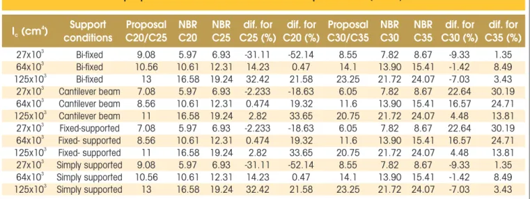
(see Table 11). In general, the values obtained by the proposal are smaller, however, it is emphasized here that the numerical analyses have been performed with the use of a damage model which consid-ers the cracking distributed in the structural element, then it is natural the contribution of the boundary conditions in this cracking panorama. It is possible to note on the table above, in general, the proposed model for Mr presents lightly superior values than NBR’s for the cases of small inertias of the transversal section. Moreover, the proposed model presents results more closer to the NBR Procedure for the cases of medium inertias and presents smaller values than NBR’s in the case of bigger inertias. It can be noted that the proposed model for C30/C35 has presented a better behavior than the proposal for C20/ C25 when compared with the values presented by NBR.
On the other hand, in the case of the evaluation of the displace-ments, according to Materials Strength Theory, such calculation in structures can be a given function, in a general way, by:
(28)
c 3 apEI
l
p
α
×
×
=
d
where αap is a constant dependent on the boundary condition, p is the acting loading, l is the effective span length, IC is the inertia moment of the transversal section and E is the concrete elasticity modulus. It can be observed that the main parameters involved in the problem, accord-ing to the results of ANOVA methodology, are contemplated in Eq. (28). Nowadays, NBR6118:2007 [1] uses a procedure where the inertia moment of the transversal section is decreased when the cracking process takes place. This penalization procedure is homogeneous leading to only one value for the inertia moment to the whole beam. In this work, the stiffness degradation is focused on the decreas-ing of the Elasticity Modulus accorddecreas-ing to the approach given by Continuum Damage Mechanics.
It can be observed that when there is a cracking processes in prog-ress, the Elasticity Modulus is function of a variable that deines the concrete cracking stage. This variable can be understood as dam-age (D). However, the own damdam-age is dependent on the deforma-tion of the structural system and related stresses. Such stress and strain states depend on the loading level applied in the structure, i.e., there is a non-linear relation in this whole process.
It can be observed that a relation that selectively degrades the
stiffness of the structure by means of the Elasticity Modulus of the cracked concrete in different phases until its collapse, it is desir-able. Even more if the parameters involved in this relation are of current use in the Structural Engineering. Therefore, it is proposed that the Elasticity Modulus be used in Eq. (28) as:
(29)
0
E
D
1
E
=
(
-
)
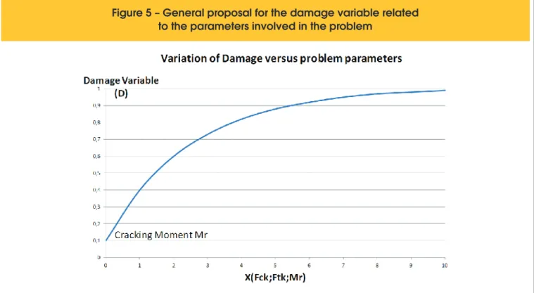
where E0 is the Elasticity Modulus of the virgin concrete obtained by NBR 6118:2007 [1]. On the other hand, the damage process is dependent on the variables involved in the problem, such as: cracking moment, compression and tension strength of the con-crete. It is also proposed that the damage variation is given by a non-linear relation illustrated in Fig. (5) and that it is dependent on the class of the concrete.
However, there are two ways to follow: it can be proposed an equa -tion for variable D with the important parameters obtained by ANO-VA or, it can be proposed an equation for D based in a regression, taking as a basis the numerical results obtained so far.
It is adopted the irst option because it works with parameters with a more tangible physical meaning for the engineers, always remember-ing that this is the philosophy used here. Moreover, the second option demands the complexity of working in several dimensions with a enor-mous range of results. This can be studied in a future work.
Therefore, following the chosen option, in a given state of the efforts x displacements, it can be calculated the stiffness of the structural ele-ment keeping unchanged the inertia moele-ment of the transversal sec-tion and using the Elasticity Modulus updated by Eq. (29) for a given acting bending moment on the most loaded section, since the acting bending moment be superior to the cracking moment of the structural element calculated by Eqs. (26) or (27). After some studies and, hav -ing as a basis a simple but eficient damage model, it is proposed the following expression for estimation of the variable D:
(30)
(
)
( )úûù
êë é
-=
r actm M M
1000 f a r
e
A
M
A
1
M
1
D
Table 11 – Values of the cracking moment given by
proposed method and NBR6118:2007 procedure (KN.m)
4
I (cm )
cSupport
conditions
C20/C25
Proposal
C20
NBR
NBR
C25
C25 (%)
dif. for
C20 (%)
dif. for
C30/C35
Proposal
NBR
C30
NBR
C35
C30 (%)
dif. for
C35 (%)
dif. for
where Ma and Mr , are given in KN.m, A parameter is a value de-pendent on the concrete class and fctm is the medium direct tension strength or characteristic of the concrete given by Eq. (31) in MPa.
(31)
3 / 2 ck ctm
0
,
3
f
f
=
Fig. (6) presents a D x Ma graphic for a class C25, Mcr = 9,35 KN.m
and A = 0,9. The use of Eq. (30) leads to a non pronounced stiffness degradation what generates a more realistic structural behavior. Finally, the proposed model is used in the case of the beam tested in reference [6]. Such beam has been chosen because there is detailed information about the experimental test, as well as about the obtained values, giving a reliability for the compari-son of results.
In Table 12, the values experimentally obtained for Ma,exp (acting bending moment), Mr,exp (cracking moment), δexp (displacement of the middle span), are compared with the values analytically
Figure 5 – General proposal for the damage variable related
to the parameters involved in the problem
obtained by NBR 6118:2007 (Mr,NBR, δNBR) and by the proposed methodology (Mr,proposto, δproposto).
It can be observed results more realistic obtained by the use of the proposed model related to the experimental results than the ones obtained with the use of the procedure suggested by NBR. However, it is necessary to think about the existence of some safety reservation for the evaluation of displacement. Fig. (7) shows the comparison of the experimental results with those obtained by NBR and by the methodology proposed in this work.
Note that the proposed model to the evaluation of the delections in the reinforced concrete structures depends on a deeper study on the results obtained so far for the conventional concretes (C20 to C35). In this sense, it is necessary to obtain more reliable experi-mental results for the validation of the proposal of this work, as well as for studies about its limitation and veriication related to safety use. These features will be studied in a future work.
Table 12 – Values of the acting and cracking moments (KN.m) and displacement (mm)
given by the experimental responses, proposed method and NBR6118:2007 procedure
M
a,expM
r,expM
r,NBRM
r,proposalδ
expδ
NBRδ
proposal–
10.64
19.69
32.02
55.77
81.89
19.69
–
–
–
–
–
8.66
–
–
–
–
–
9.35
–
–
–
–
–
–
0.8
2.3
3.0
7.0
11.5
–
1.3
2.8
4.6
8.1
11.9
–
1.16
2.29
3.93
7.36
11.62
Figure 7 – Comparison between experimental response and results
obtained by the proposed method and NBR procedure
5. Conclusions
In this work a damage model for the concrete proposed by [3] has been used in the evaluation of delections in reinforced concrete structures.
dis-placement values. On the other hand, the damage model degrades the stiffness in a selective way, therefore it is possible to consider the contribution of tensioned concrete between cracks. However, the existence of a safety reservation always must be necessary. In a general way, the ANOVA methodology shows the variables that must be contained in an eventual alternative formulation to the NBR6118:2007 Procedure [1]. Such proposal has been presented at the end of this work, where the focus about stiffness penaliza-tion becomes the Elasticity Modulus, following the basis given by Continuum Damage Mechanics. Initial tests have been performed in this work and the results shown the potentialities of the proposed methodology employment, but its effective validation and use limi-tation study will be objects of future studies. Besides, it is neces -sary to verify the use safety of the proposal in practical applications of the Structural Engineering. In sum, the results presented in this work encourage the authors to proceed in the development of this proposed methodology.
7. Acknowledgement
The inancial support from CNPq (National Council for Scientiic and Technological Development) is gratefully acknowledged.
8. References
[01] ASSOCIAÇÃO BRASILEIRA DE NORMAS TÉCNICAS. NBR 6118:2007, Projeto de estruturas de concreto – Pro -cedimento. Rio de Janeiro, 2004.
[02] PITUBA, J. J. C., DELALIBERA, R. G., and RODRIGUES, F. S.. Numerical and statistical analysis about displacements in reinforced concrete beams using damage mechanics. Com-puters and Concrete, an International Journal, Vol. 10(3), 307-330, 2012.
[03] PITUBA, J. J. C.. and FERNANDES, G. R.. An anisotropic damage for the concrete. Journal of Engineering Mechanics - ASCE, Vol. 137(9), 610-624, 2011.
[04] PITUBA, J. J. C.. and LACERDA, M. M. S.. Simpliied dam -age models applied in the numerical analysis of reinforced concrete structures. IBRACON Structures and Materials Journal, Vol. 5(1), 26-37, 2012.
[05] MONTGOMERY, D. C.. Design and analysis of experiments, Arizona State University, 4th Edition, John Wiley & Sons, 1996.
[06] DELALIBERA, R. G.. .Análise teórica e experimental de vi -gas de concreto armado com armadura de coninamento. Dissertação de Mestrado, Escola de Engenharia de São Carlos, Universidade de São Paulo, 2002.
[07] VECCHIO, F. J. and Emara, M. B.. Shear deformations in reinforced concrete frames. ACI Structural Journal, Vol. 89, n. 1, p. 46-56, 1992.