Resumo
Nesse trabalho, apresenta-se um modelo numérico para a análise não-linear estática e dinâmica de vigas, placas e cascas de concreto reforçado. Sendo assim, procedimentos de análise, baseados na teoria da plasticidade e com monitoramento de issuração, são desenvolvidos. Elementos initos de casca degenerada de 9 nós são usados na análise estática, enquanto elementos initos de 20 nós são considerados para a análise dinâmica. A lei constitutiva do concreto é acoplada a um modelo sensível à velocidade de deformação, para se terem em conta os efeitos produzidos para altas velocidades de deformação. O procedimento de Newmark é adotado para a integração no tempo do sistema não-linear de equações. Considera-se que o aço de reforço está perfeitamente distribuído e aderido ao concreto, sendo esse representado por elementos initos de membrana. Vários exemplos são solucionados com o presente modelo numérico e os resultados obtidos são conferidos com os resultados de outros autores. Para todos os casos, o caminho de falha, o carregamento de colapso e o mecanismo de falha são reproduzidos com suiciente precisão.
Palavras chaves: Estruturas de concreto reforçado, método dos elementos initos (MEF).
Abstract
A numerical model using the Finite Element Method (FEM) for the nonlinear static and dynamic analysis of reinforced concrete (RC) beams, plates and shells is presented in this work. For this purpose, computer programs based on plasticity theory and with crack monitoring capabilities are developed. The static analysis of RC shells up to failure load is carried out using 9-node degenerated shell inite elements while 20-node brick inite elements are used for dynamic applications. The elasto-plastic constitutive law for concrete is coupled with a strain-rate sensitive model in order to take into account high loading rate effect when transient loading is intended. The implicit Newmark scheme with predictor and corrector phases is used for time integration of the nonlinear system of equations. In both cases, the steel reinforcement is considered to be smeared and represented by membrane inite elements. Various benchmark examples are solved with the present numerical model and comparisons with other published data are performed. For all examples, the path failure, collapse loads and failure mechanism is reproduced with great accuracy.
Keywords: Reinforced concrete (RC) structures, inite element method (FEM).
Numerical modeling of
reinforced concrete structures:
static and dynamic analysis
Modelagem numérica de estruturas de concreto
armado: análise estática e dinâmica
Jorge Luis Palomino Tamayo Msc, Researcher, Applied and Computational Mechanical Center of the Federal University of Rio Grande do Sul-CEMACOM-UFRGS [email protected]
Armando Miguel Awruch D.Sc, Professor,
Federal University of Rio Grande do Sul-UFRGS [email protected]
Inácio Benvegnu Morsch D.Sc, Professor,
Federal University of Rio Grande do Sul-UFRGS [email protected]
1. Introduction
The inite element method allows the solution of complex problems, such as those represented by the nonlinear behavior of reinforced concrete struc-tures. Any reinforced concrete structural system may be subjected to static or dynamic loading during its life. Under-stating of the structural response to such
loads is essential in order to protect in-frastructure. Due to the ininite number of permutations of structural parameters and due to the cost of experimental tests, it is desirable to employ a numerical tool for the prediction of the structural response. In this work, a computer code is implemented for such purpose. A
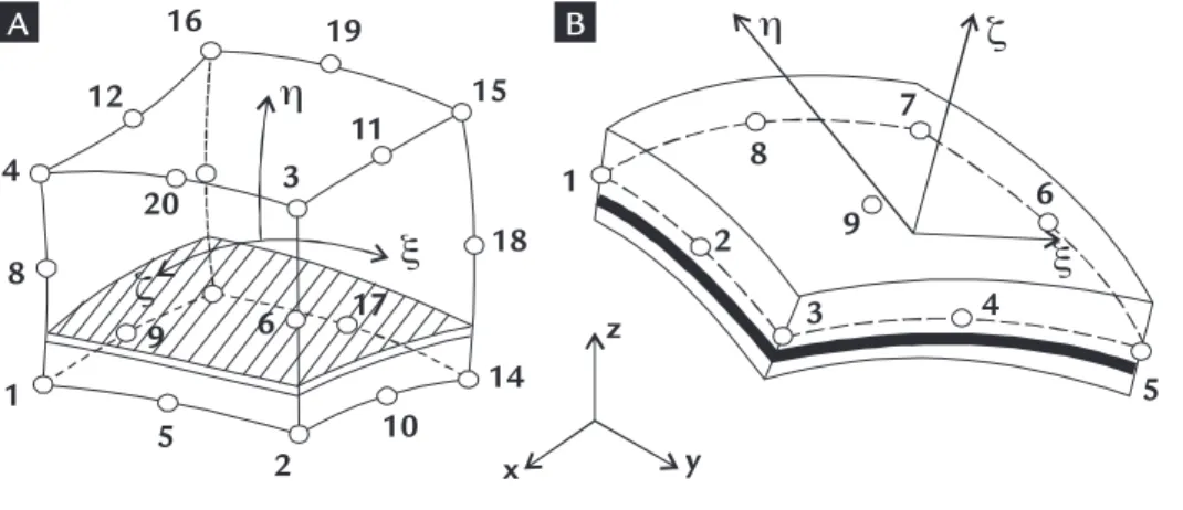
de-generated shell element and a 3D brick inite element based on a displacement approach are implemented in order to simulate the numerical response for static and dynamic analysis (See Figure 1). Reliability of the present numerical code is demonstrated by the solution of several examples.
Figure 1 Local systems.
A) 20-node brick element.
B) 9-node degenerate shell element.
2. Methodology
Finite element formulation
The 9-node degenerated shell ele-ment is used here for the assessele-ment of the path failure of reinforced concrete shells under static loads. The displace-ment ield within the eledisplace-ment is deined in terms of quadratic shape functions and displacement values at nodes. The steel reinforcement is considered to be
perfectly bonded to the surrounding concrete and smeared within the ele-ment. Several concrete and steel layers are deined through thickness in order to capture properties variations due to nonlinearities. Otherwise, 20-node brick elements are used here for dynamic analysis where steel reinforcements are
also modeled using a smeared approach. Because both elements are widely used and are well documented in the literature of the topic, the reader is referred to the works of Tamayo (2011) and Cervera et al. (1988) for a detailed description of the inite element formulation and numerical implementation of these elements.
Constitutive models
For describing material nonlineari-ties introduced due to cracking of concrete in tension and nonlinear behavior in compression as well as yielding of the steel reinforcement in tension and compression, the associated theory of plasticity is used. A modiied Ducker-Prager yield criterion coupled with a crack monitoring algo-rithm (see Cervera et al., 1988) is used to deine the complete behavior of concrete in the nonlinear regime. For concrete in compression, a nonlinear hardening model based on a uniaxial law is considered. The crushing condition is calculated in terms of the irst invariant of the strain tensor and the second invariant of the strain deviator tensor. This condition is activated each time that an ultimate compressive strain value (which was adopted as being 0.0035) is reached. The response of concrete under tensile stresses is assumed to be bilinear elastic until the fracture surface is reached
and then, its behavior is characterized by an orthotropic material. The cracking is governed by a maximum strain criterion. Cracks are assumed to occur in planes perpendicular to the direction of the maximum principal strain as soon as this strain reaches the speciied concrete tensile strain. After cracking has occurred the elastic modulus and Poisson’s ratio are assumed to be zero in the perpendicular direction to the cracked plane, and a re-duced shear modulus is employed. Due to bond effects, a tension stiffening model is considered. In this way, concrete between cracks carries a certain amount of tensile force normal to the cracked plane. The steel reinforcement is modeled as a uni-axial elastoplastic material following a bi-linear diagram which unloads elastically. Further details of the material models can also be found in Tamayo, (2011) and Cervera et al. (1988).
Up to this moment, the main fea-tures for the constitutive model for con-crete have been described. Apparently, these features are suitable only for static analyses because earlier developments and studies suggest that a concrete model intended for transient analysis should be rate and history dependent. Therefore, the described elasto-plastic model seems not to meet these requirements and modiica-tions are needed. However, Cotosovos and Pavlovic (2008) have explained that the apparent strength gain at high loading rates is related to the inertial loads which reduce the rate of cracking and not to the constitutive model itself. Therefore, the use of a constitutive model which is dependent on the strain rate loading is questionable. At present time, it seems that all investigators are not in agree-ment with respect to this issue, in spite of the great amount of experimental and
1
1
2
2
η
η
ξ
ξ
ζ
ζ
3
3 4
4
5
7
5 6
6
17 19 16
20 8
8
9
9
10 18
14
x y
z 15
12
11
analytical data. This work has not the objective to discuss this aspect in detail, so the strain-rate sensitive model proposed by Liu and Owen (1986) is implemented
as an option. In this model, the dynamic yield surface is not only dependent on the total plastic strain, but is also a function on the magnitude of current strain rate.
Again, the reader is referred to the given reference for a detailed description of the formulation and a complete low diagram for the numerical implementation.
Numerical algorithm
The nonlinear transient dynamic equation at time station tn+1 is governed by the following equation:
[M]{a}
n+1+ [C]{v}
n+1+ [K]{d}
n+1= {f}
n+1 (1)where [M], [C], [K], and {f} are the mass, damping, tangential stiffness matrices and force vector, respectively. {a}n+1, {v}n+1 and
{d}n+1 are the acceleration, velocity and displacement vectors. In the Newmark scheme the displacement and velocity at
time tn+1 can be expressed in the follow-ing form:
{d}
n+1={d}
n+1+ Dt
2b{a}
n+1 (2)
{v}
n+1={d}
n+1+ Dtg{a}
n+1 (3){d}
n+1={d}
n+ Dt{v}
n+ Dt
2(1/2-b
){a}
n+1 (4)
{v}
n+1={v}
n+ Dt(1 - g
){a}
n+1 (5)where
b=0.5 and b=0.25 are free parameters which control the accuracy and stability of the method.
The values {d}n+1 and {v}n+1 are the predic-tor values and {d}n+1 and {v}n+1 are the corrector values. The reader is referred to Cervera et al. (1988) for a detailed
imple-mentation of the present algorithm. It is important to establish that this algorithm also serves for static loading case when inertial and damping terms are neglected.
3. Numerical examples
Geometrically nonlinear reinforced cylindrical shell experimentally tested by Bouma et al. (1961)
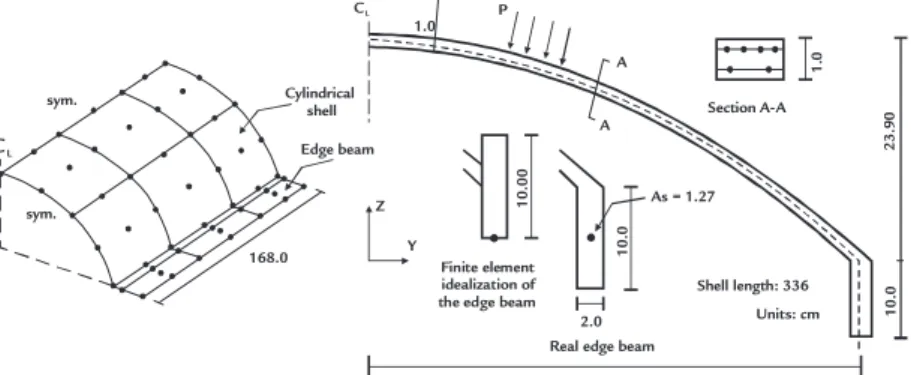
A cylindrical shell subjected to uniformly distributed pressure load P, which was tested by Bouma et al. (1961), is analyzed with the present inite element code, which includes a total Lagrangian scheme to analyze geometrically nonlinear problems. This 1/8-scale model has rect-angular beams at its longitudinal edges with a total amount of reinforcement of 1.27 cm2 in each one. For a detail descrip-tion of the reinforcement arrangement in the cylindrical part, the reader is referred to the work of Chan (1982). The material properties are listed in Table 1. Because of symmetry, only a quarter of the structure was modeled with six shell degenerated elements for the cylindrical part and three
shell elements for the edge beam. The edge beam is modeled by elements lying in the horizontal plane because the shell elements are much more accurate in out plane bend-ing than in in-plane bendbend-ing. Then, it is necessary to deine three additional shell elements along the edge beam to permit the abrupt change of thickness from the cylindrical part to the edge beam (See Figure 2). All shell elements are divided into eight equal concrete layers through thickness.
The computational model, also, considers that the cylindrical shell middle surface is attached to the middle line of the edge beam. As shown in Figure 2, the position of the steel reinforcement in
the edge beam remains unchanged. As the overall response of the structure is of interest, this simpliied model is considered to be adequate. A more accurate descrip-tion of the path failure of the structure will require the correct modeling of the eccentricity of the edge beam and probably to the use of 3D beam-column elements rigidly attached to the middle surface of the shell. The resulting load-displacement response at the free edge is depicted in Figure 3, together with experimental test results presented by Bouma et al. (1961) and numerical results obtained by Arnesen et al. (1980) and Chan (1982). Acceptable agreement is found in the determination of the collapse load and path failure.
Figure 2 Geometry and inite element mesh of the reinforced concrete shell.
sym.
sym. Cylindrical
shell
168.0 Z
Y
65.25 Real edge beam
Shell length: 336
Units: cm As = 1.27
Section A-A A
A P
Finite element idealization of the edge beam
2.0 1
0
.0
1
0
.0
0
2
3
.9
0
1
0
.0
1
.0
1.0
Edge beam CL
Table 1
Material properties for studied examples.
Figure 3
Midspan delection of edge beam given by various authors.
Material
Example
Shell KN, cm
Beam Kip, in (N, mm)
Slab N, mm
Concrete Young’s modulus
Poisson’s ratio Ultimate compressive stress Ultimate compressive strain
Cracking strain Mass density
3000.0 0.15
3.0 0.0035 1.70E-04
0.0E-00
6100.0 (42059.5) 0.20 3.74 (25.8)
0.0035 0.750E-04 0.217E-06 (193.2)
28000.0 0.20 35.0 0.0035 1.50E-04 0.245E-08
Steel Young’s modulus
Yield stress Hardening modulus
21000.0 29.5 20.0
30000.0 (206850.0) 44.0 (303.4)
0.0 (0.0)
210000.0 460.0
0.0
Simply supported beam
A simply supported reinforced con-crete beam shown in Figure 4 is subjected to two symmetrically applied concentrated loads which are applied as step loads with a zero rise time. The problem has been solved by Beshara and Virdi (1991) and Cervera et al. (1988). The beam is rein-forced in the lower position by 2 in2 (1290 mm2) steel area. The material properties are listed in Table 1. Using symmetry conditions only one half of the beam is modeled using ive 20-node isoparamet-ric bisoparamet-rick elements with an embedded
membrane element to simulate the steel reinforcement. The dynamic analysis is evaluated with a time step of 0.0005 sec. No viscous damping is considered. As a check, an elastic analysis (not shown) was irst performed, and the results found here are in excellent agreement with those given in Cervera et al. (1988). In Figure 5, the central delection history of the nonlinear case, considering and not considering the strain-rate sensitive model compares well with the results obtained by Cervera et al. (1988) who used a strain-rate sensitive
elasto-viscoplastic model.
In Figure 6, results obtained by Be-shara and Virdi (1991) using an elasto-vis-coplastic either strain-rate or not strain-rate sensitive model are depicted. These results serve as a base of comparison to see the tendency and the effect of the rate sensitive model. Some differences are encountered with the present results because in the given reference a different time step was used, but the overall proile response is quite similar. As expected, the use of a strain-rate sensitive model decreases the delection.
Figure 4
Loading, geometry and inite element mesh of reinforced concrete beam.
0 10 20 30 40 50
0 10 20 30 40 50
Midspan vertical downwards displacement of edge beam (mm)
T
o
ta
l
lo
a
d
(
k
N
)
Experimental Bouma et al. (1961)
Chan (1982)
Arnesen et al. (1980)
Present analysis
6
Units (in) 13.5
P (kips)
Time (s)
1
1 2.00 in²
20 18
0.5P
CL
Figure 5 The effect of strain rate on the nonlinear response of the beam for the present model.
Figure 6 The effect of strain rate on the nonlinear response of the beam by Beshara and Virdi (1991).
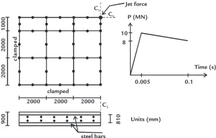
Rectangular reinforced concrete slab
The clamped reinforced concrete slab shown in Figure 7 is subjected to a jet force at the center. The percentage of steel reinforcement placed on the up-per and lower layers in each direction is 1.5%. The material properties of the concrete and steel are given in Table 1. The selected time step is 0.001 s. From
symmetry, only one quarter of the slab is considered. The inite element mesh is also shown in Figure 7. Nine 20-node elements with ifteen integration points are used in the analysis. In Figure 8, the central displacement response of the concrete slab is determined and compared with the results obtained
by Ayyad (2003) and by Haido et al. (2010) who used layered shell elements. Results are in agreement with those obtained in the previous references. In this example the inluence of the strain-rate sensitive model in the inal response of the plate was found not to be of signiicance.
Figure 7 Loading, geometry and inite element mesh of the clamped reinforced concrete slab.
4. Final discussion and conclusions
The numerical results obtained with the present numerical model are found to
be satisfactory for both static and dynamic loading. Apparently, more experimental
and analytical evidence is needed for the constitutive model of concrete in the case
0
Time (s)
C
e
n
tr
a
l
d
is
p
la
c
e
m
e
n
t
(i
n
)
Present analysis (nonlinear rate independent) Present analysis (nonlinear rate dependent) Cervera et al. (1988)
0.00 -0.05 -0.10 -0.15 -0.20 -0.25 -0.30 -0.35
0.01 0.02 0.03 0.04 0.05
Beshara and Virdi (1991) (nonlinear rate independent) Beshara and Virdi (1991) (nonlinear rate dependent)
0
Time (s)
C
e
n
tr
a
l
d
is
p
la
c
e
m
e
n
t
(i
n
)
0.00 -0.05 -0.10 -0.15 -0.20 -0.25 -0.30 -0.35 -0.40
0.01 0.02 0.03 0.04 0.05
2000
clamped
c
la
m
p
e
d
2
0
0
0
2000
Units (mm)
2
0
0
0
2000 C L CL
CL
0.005 Jet force
P (MN)
Time (s) 8
10
0.1
1
0
0
0
9
0
0
8
1
0
Figure 8
Nonlinear dynamic response of reinforced concrete slab.
5.
Acknowledgement
The inancial support provided by CAPES and CNPQ is gratefully acknowledged.
6. References
ARNESEN, A., SORENSEN, S.I., BERGAN, P.G. Nonlinear analysis of reinforced concrete. Computers and Structures, v. 12, n. 4, p. 571-579, 1980.
AYYAD, H.I.A. Nonlinear dynamic analysis of reinforced concrete stiffened shells using the inite element method. Mosul: University of Mosul, 2003. (PhD thesis).
BESHARA, F.B.A., VIRDI, K.S. Nonlinear inite element dynamic analysis of two-dimensional concrete structures.
Computers and Structures, v. 41, n. 6, p. 1281-1294, 1991.
BOUMA, A.L., VAN RIEL, A.C., VAN KOTEN, H., BERANEK, W.J. Investigations on models of eleven cylindrical shells made of reinforced concrete and prestressed concrete. In: SYMPOSIUM ON SHELL RESEARCH, Delft, 1961. CERVERA, M., HINTON, E., BONET, J., BICANIC, N. Nonlinear transient dynamic analysis of three dimensional
structures - A inite element program for steel and reinforced concrete materials. In: HINTON, E. (ed.). Numerical methods and software for dynamic analysis of plates and shells. Swansea: Pineridge Press, 1988. cap. 7, p. 320-504. 550p.
CHAN, E. Nonlinear geometric, material and time dependent analysis of reinforced concrete shells with edge beams. Report UCB/SEMS-82/08, 1982.
COTSOVOS, D.M., PAVOLIC, N. Numerical investigation of concrete subjected to compressive impact loading Part 1: A fundamental explanation for the apparent strength gain at high loading rates. Computers and Structures, v. 86, n. 1-2, p. 145-163, 2008.
HAIDO, J.H., BAKAR, B.H., RAZZAK, A.A., JAYAPRAKASH, J. Dynamic response simulation for reinforced concrete slabs. Simulation Modelling Practice and Theory, v. 18, n. 6, p. 696-711, 2010.
LIU, G.Q., OWEN, D.R.J. Ultimate load behavior of reinforced concrete plates and shells under dynamic transient loading. International Journal for Numerical methods in Engineering, v. 22, n. 1, p. 189-208, 1986.
TAMAYO, J.L.P. Analise numérica de vigas mistas pelo método dos elementos initos. Porto Alegre: PPGEC - Universidade Federal do Rio Grande do Sul, 2011. (Dissertação de Mestrado).
Artigo recebido em 11 de setembro de 2012. Aprovado em 31 de maio de 2013. of dynamic loading. The development of
the proposed model is still in progress where the formation of three mutual per-pendicular cracks should be considered. A systematic study of cracking, elasto-plastic yield and strain rate effect of concrete af-fecting the behavior of reinforced concrete structures are continuing.
The numerical procedures pre-sented here allow the correct description of the nonlinear response of RC beams, plates and shells. Benchmark examples found in literature are reproduced and obtained results compared well with
other published data. In addition, it seems that for the present applications, only two mutually perpendicular cracks are enough to describe the path failure. However, the formation of three mutu-ally perpendicular cracks should be considered for different loading condi-tions and other structures such as piles. This last option will be implemented in future works. The use of the strain-rate sensitive model yields logical results and prove to follow the same proile obtained by Beshara and Virgi (1991) for the beam. Also, this rate effect was
found to be more important where com-pression dominates. Finally, the present strain-rate sensitive elasto-plastic model (Liu and Owen, 1986) seems to be more advantageous when compared to the strain-rate sensitive elasto-viscoplastic model presented by Cervera et al. (1988) because fewer model parameters are needed. Various tension stiffening mod-els were tested for the given examples, varying only on the shape of the de-scending curve. It was found that the peak displacement response could vary at most 7%.
0
Haido et al. (2010) Ayyad (2003) Present analysis 0
-1 -2 -3 -4 -5 -6 -7 -8 -9
0.01 0.02 0.03
Time (s)
C
e
n
tr
a
l
d
is
p
la
c
e
m
e
n
t
(m
n