In this work, the overlapping crack mode is considered. It permits the modeling of concrete crushing through cohesive surfaces, in a similar way used to simulate fracture. The material is considered in damage when the surfaces interpenetrate each other. Besides simplicity, the big advan-tage of the methodology is the fact that constitutive relations are independent of the material scale. A generalization is here introduced to consider mixed crushing. Exploratory applications are made considering super-reinforced beams. The effects of the height of the beams, compressive
rebars and stirrups are investigated. A good itting with experiments is obtained.
Keywords: reinforced concrete, crushing, cohesive models, inite elements.
Neste trabalho é empregado o modelo de trincas sobrepostas, que permite modelar o comportamento em esmagamento do concreto através de superfícies coesivas, de forma similar à empregada na simulação de fraturas. O material entra em dano de compressão quando há interpe-netração das superfícies. Além da simplicidade, a grande vantagem da metodologia é estar baseada em relações constitutivas independentes da escala do material. Uma generalização é introduzida de modo a considerar o modo misto de esmagamento. Aplicações exploratórias são realizadas considerando vigas super-armadas de concreto. Investigou-se o efeito da altura das vigas, das armaduras de compressão e dos estribos. Um bom ajuste com dados experimentais é obtido.
Palavras-chave: concreto armado, esmagamento, modelos coesivos, elementos initos.
Consideration of reinforced concrete crushing through
cohesive models
Consideração do esmagamento no concreto armado
através de modelos coesivos
T. B. EVANGELHO a
E. BITTENCOURT a
a Universidade Federal do Rio Grande do Sul, Departamento de Engenharia Civil, Escola de Engenharia, Porto Alegre, Brasil.
Received: 26 Nov 2013 • Accepted: 10 Mar 2014 • Available Online: 02 Jun 2014
Abstract
1. Introduction
The post-peak behavior of concrete under compression has funda-mental importance on ductility of it, modifying the ultimate behavior of reinforced concrete beams. The fact that post-peak stress-strain rela-tions are strongly dependent on the scale [1] makes the objectivity of the analysis of such cases extremely doubtful. The strong localization of strains observed in the post-peak failure is another important char-acteristic. It indicates that the energy dissipation in this stage occurs in fact at internal surfaces of the material and not in volume [2]. Due to these two aspects, Carpinteri et al. [3,4] and Corrado [5] pro-posed a methodology to model concrete crushing using a method-ology similar to the cohesive models used in Fracture Mechanics [6,7]. In the cohesive models, cracking is represented discretely by surfaces that separate each other symbolizing the crack opening. In the crushing model these surfaces overlap each other when there is compression. Such methodology is named “the overlapping crack model” by the authors and it is based on Fracture Mechanics prin-ciples. Then the constitutive law to represent the post-peak behavior
of the concrete in compression is deined by a stress-displacement
relation. The constitutive law is then not prone to objectivity prob-lems, i.e. it is not dependent on the scale, as experimentally
con-irmed by van Vliet and van Mier [8] and by Jansen e Shah [9].
In the present work, the overlapping crack model [3-5] together with the cohesive crack model [7] are used in order to simulate completely the failure process of different reinforced concrete beams. Only super-reinforced beams are considered. In these
cases, concrete is crushed in the inal stages of the failure process.
The overlapping crack model is here generalized in order to con-sider mixed mode fracture (shear effects), although such cases will not be considered in the experiments. In the chapter 2 is initially described the overlapping crack model considering only normal
tractions and then modiications are introduced to consider mixed
mode. In the chapter 3, numerical simulations are done. Beams
with different sizes and stirrup types are considered. The effect of compression rebars is also investigated. Final remarks are made in chapter 4.
2. The overlapping crack model
In this chapter, the overlapping crack model is described for two situations. First, the case where the cohesive surface is under nor-mal tractions only is considered and, second, a general situation is taken into account, where the surface is under normal and shear
tractions. Implementation of the model in a inite element context
is also described.
2.1 Consideration of normal tractions
Two internal surfaces of the body are considered where the
sepa-ration between them is deined as w. If the surfaces open
(crack-ing) the separation is positive and will be here identiied by variable wt. A traction s is then created. As it opposes opening, it is called a
cohesive traction [6,7]. If the surfaces overlap (crushing) the
sepa-ration is negative and will be here identiied by variable wc. A
trac-tion s is also created in this case, opposing the overlapping. The constitutive relation s versus wc is the crushing constitutive law. In
the present work such relation is separated in two parts: the pre-peak and the post-pre-peak.
The pre-peak relation is elastic-linear and is valid for tractions smaller than compression strength (σc). The overlap
correspond-ing to this situation is identiied by wc
e and must be minimal [10].
The pre-peak relation does not exist in the original overlap crack
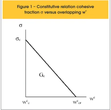
model. The post-peak relation is deined in Figure 1.
The area under the traction-overlap curve is designated crushing
speciic energy (Gc), in analogy with the speciic energy of frac
-ture (Gf), which is the area under the traction-opening curve. The
overlapping model takes into account, in a simpliied way, complex
phenomena linked to crushing as fragmentation and propagation of micro-cracks in shear. Then Gc can be interpreted as the sum of the energy dissipated by micro-cracks during crushing plus fric-tion effects [11]. As a consequence, Gc is, in general, two or three orders of magnitude greater than Gf . For plain concrete with sc ranging from 20 to 90 MPa, corresponding Gc ranges from 30 to 58 N/mm [12,13]. However, the most basic aspect to be considered here is that Gc as well as the traction-overlap relation are concrete properties and are independent of the scale.
Suzuki et al. [13] established models to take into account the
con-inement effect due to stirrups. The authors determined relations
of Gc with the steel yield stress used in stirrups as well as with the volume fraction of stirrups. The presence of stirrups increases considerably Gc and critical overlap wc
cr . For instance, values in
the order of up to 500 N/mm are reported to Gc in case of a high volume fraction of stirrups.
2.2 Mixed mode considerations
The original overlapping crack model [3-5] considers that cohe-sive surface is subjected to normal tractions only. In this work a generalization is proposed in order to include the effect of shear tractions τ.
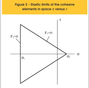
Shear effects are here considered irrelevant until a limit deined
by the Mohr-Coulomb relation is attained. This condition can be
Figure 1 – Constitutive relation cohesive
c
seen in Figure 2. F1=0 represents the traction limit according to the Mohr-Coulomb failure criterion, while F2=0 represents the traction limit linked to crushing. F1 and F2 are deined below, where φ is the concrete friction angle and σt its tensile strength.
(1)
F
1=|
t
|-(
s-st
)tan
f
;
F
2=
s-sc
If F1 and F2 are smaller than zero, material behavior is elastic. Graphically this situation corresponds to the internal region of the triangle shown in Figure 2. Tractions outside the triangle (F1 and/or F2> 0) are forbidden and must return to the surface. In this return process irreversible (or “plastic”) deformations are created, which are the responsible to damage the material. For instance, if F2> 0, the return process creates irreversible values of wc that ultimately will decrease compression strength
σc , according to relation shown in Figure 1. Graphically this
situation can be seen as the line F2=0 moving toward the right, in Figure 2. The process is completed when σc =0, i.e. the
ma-terial is completely damaged, without any strength. Details re-garding the return process can be find in Evangelho [10] and Lens et al. [7].
2.3 Implementation in inite elements
In order to implement the methodology in a inite element context,
internal surfaces are created using duplicated nodes in the mesh. Then the link between elements is done by cohesive tractions and not by the connectivity as in a standard methodology.
Once the surfaces are deined, opening and overlapping can be
calculated and then cohesive tractions, following the procedures described above. Nodal forces can be obtained from the spatial integration of tractions. These forces are added to the global
as-semble of forces computed by standard inite element procedures. All non-linearity is conined to cohesive surfaces. The explanation
for such restriction is based on the damage nature of the concrete,
which is conined at surfaces, the volume remaining elastic-linear. Balance equations are satisied through the use of the Newton-Raphson solution method. The volumetric inite element used is
a linear four-node isoparametric with Lagrangean interpolation function.
3. Numerical experimentation
In this chapter, isostatic three-point beams of reinforced concrete are tested. Two points support the beams at the borders and are symmetrically loaded at the center, as seen in Figure 3. Plane strain state is considered. In the numerical modeling, rebars are replaced by a layer of steel with an equivalent height. This height is obtained by dividing the total cross section area of the rebars by the thickness of the beam. The equivalent layer is placed in the same position of the rebars.
The dotted horizontal line at the bottom of the beam in Figure 3 indicates the position of the tensile rebars and the dotted horizontal line at the top the position of the compression rebars. Based on physical observations, it is assumed that crushing process is totally localized at the central transversal section. Cracking is also con-sidered localized at the same section, so all cohesive elements are placed in a central line, perpendicular to the length of the beam, as indicated by the dotted vertical line in Figure 3.
Four different beams are numerically simulated in this work and compared to experimental results of Burns and Siess [14]. Table 1 gives a description of the analyzed beams (denomination follows reference [14]).
Figure 2 – Elastic limits of the cohesive
elements in space
s
versus
t
Figure 3 – Geometry of the beams
used in simulations
Table 1 – Characteristic of the tested beams [14]
Beam
s
ch (mm)
d (mm)
(MPa)
(MPa)
s
escJ1
J2
J10/J19
305
305
405
255
255
355
34
28
25
σο
esc is the initial yield stress of the rebars. In all cases the same
tensile rebars are used: two bars with 25,4 mm diameter. J2 beam is the only with compression rebars. They are two with 19 mm di-ameter and placed at d’=50 mm (Figure 3). The steel is considered
elastic-plastic with non-linear hardening deined by equation 2:
(2)
s
esc=s
0esc+(
s
¥esc-
s
0esc)[1-exp(-k
e
pl)]
where εpl is the plastic strain. For the constants σ∞
esc and k the
val-ues 500 MPa and 2.5 are adopted, respectively, in order to adjust the stress-strain relation for the steel.
Except for case J19, all beams have stirrups with diameter equal to 9.5 mm. In case J19 stirrups have a diameter equal to 6.3 mm. In all cases spacing is equal to 150 mm.
Concrete-rebar bonding is modeled according the Code Model 90
[15]. Due to the presence of stirrups the conined condition was used.
The length L of the beams is always the same and is equal to 3650 mm, as well as the thickness, equal to 200 mm.
To consider cracking, tensile strength is deined as σt=0.3(σc)2/3
and Gf=0.09 N/mm in all cases.
In Figure 4 numerical results of load/delection for case J1 are
shown. Experimental results presented by Burns e Siess [14] are also shown. These authors describe the sequence of events in the experimentation as follows: elastic-linear behavior occurs only at the beginning of the test, with cracking initiating for a very low level of loading. For a loading level around 80 kN, the slope of the load/
delection curve decreases substantially. This change is linked to
the onset of steel yielding. Afterwards the concrete crushing be-gins, decreasing further the curve slope, which ultimately becomes negative. The present model captures all this sequence of events. When crushing is not considered, peak loading is over-estimated by more than 10%, as seen in Figure 4. On the other side, the crushing energy has an effect only on the ductility of the beam. For a critical overlap (wc
cr) equal to 5 mm (Gc=85 N/mm) the maximal
delection of the beam is not larger than 50 mm. For wc
cr=18 mm
(Gc=306 N/mm) the ductility is similar to ductility observed in
ex-periments, with a maximal delection equal to 120 mm.
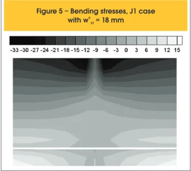
Figure 5 shows the distribution of bending stresses for the same case J1, in the central region of the beam (case wc
cr=18 mm). In the
compressed zone (top of the beam) it is observed that stresses are never greater than compressive strength. At the very center of the beam stresses are smaller due to crushing and material damage, as expected. Those observations indicate that the use of only one line of cohesive elements is enough to capture crushing effects. On the other side, in the traction zone (bottom of the beam) it is ob-served that bending stresses are greater than the tensile strength, estimated here to be around 3 MPa. This observation indicates that the use of only one cohesive line is not enough to capture completely the process of cracking in reinforced concrete. In Figure 6, J1 and J10 beams are compared. The fundamental difference between them is the larger height of the case J10. It
Figure 4 – Comparison of numerical and
experimental results [14] for J1 case. Different
critical overlaps are considered. A case
where there is not crushing is also considered
Figure 5 – Bending stresses, J1 case
c
with w = 18 mm
crcan be observed a good it with experiments, as before. In case J1 wc
cr=18 mm and in case J10 w c
cr=22 mm.
In the simulations made in the present work, cases with larger height present the trend to overestimate the load for steel
yield-ing. According to Carpinteri et al. [16], this loading is strongly inlu -enced by concrete cracking and higher beams tend to suffer more cracking. As the models used in the present work have a poor representation of cracking (Figure 5), this can be an explanation
for the dificulties observed in higher beams.
The effect of compression rebars was also investigated. Numeri-cal results are compared with experiments in cases J1 and J2 in Figure 7 (case J2 has compression rebars while case J1 does not, as described before). In both cases the same critical overlap (18 mm) is used.
According to Carpinteri et al. [16], a substantial increase in the ultimate deformation of the beam is expected when compression rebars are introduced. This characteristic is captured by the pres-ent model, as seen in Figure 7, where the deformation of J2 beam is approximately three times as much the deformation of J1 beam.
Still according to these authors, cracking has small inluence in the
ultimate behavior of this kind of beam, which is driven by crushing
phenomena. As already commented, cracking has inluence on the
onset of steel yielding, or the beginning of the plateau of the load/
delection curve, exactly where the discrepancy with experiments
is larger.
Transversal rebars (stirrups) are used basically to resist shear ef-fects. In the cases analyzed here, they are considered to be rect-angular. A decrease in the volume fraction of stirrups leads to a smaller critical overlap [12], case of the J19 beam when compared to others. In Figure 8, the behavior of J19 beam is compared with
J10 beam. In the irst wc
cr=13,75 mm and in the latter w c
cr=22 mm in
accordance with the correspondent volume of stirrups.
It can be concluded, from numerical and experimental results, that the increase in the density of stirrups implies an increase in the
beam delection, without a noticeable increase in the maximal load
supported. The reason is that stirrups basically increase ductility
via concrete coninement, resulting a greater ultimate delection.
4. Final remarks
In this work the overlapping crack model was used. The model per-mits to consider concrete crushing through traction/overlap constitu-tive laws, where scale effects are minimal. An exploratory study of the methodology was done in order to access its viability. Three dif-ferent three-point beams were considered. Numerical results were compared with experiments [14] with the following conclusions:
n Damage in the reinforced concrete occurs in the following order:
cracking, steel yielding and concrete crushing. The model present-ed in this work (cohesive models for cracking and crushing, couplpresent-ed with a discrete model for rebars and the bonding concrete/rebar) was able to capture all these phases in a relatively precise way.
n Concretes with a higher crushing energy have a more ductile
behavior. This energy increases substantially with the density of stirrups. In the case of plain concrete it is a material property.
n The methodology is able to capture automatically the effects of
com-pression rebars, which increase considerably the ductility of the beam.
n The methodology is able to capture qualitatively the effects of
stirrups on ductility.
n The methodology can be easily implemented in any non-linear inite element code.
The main goal of this work was to investigate the viability of the methodology. A more detailed study of the relations between crushing energy and density of stirrups would be very helpful. An-other interesting study would be an investigation of the shear ef-fects on crushing behavior. Such study would be fundamental to have a better understanding of rebars pull-out.
5. Acknowledgements
The authors thank CAPES and CNPq for the inancial support.
6. References
[01] Indelicato, E. and Paggi M. Specimen shape and the problem of contact in the assessment of concrete
Figure 7 – Comparison of numerical and
experimental results [14] for J1 and J12 cases.
(J2 case has compression rebars)
Figure 8 – Comparison of numerical and
experimental results [14] for J10 and J19 cases.
compressive strength. Materials and Structures, v.41, n.2, 2008; p. 431-441.
[02] Van Mier, J. G. M. Strain softening of concrete under mul-tiaxial compression, Eindhoven, 1984, Tese (doutorado) – Eindhoven University of Technology, The Netherland. [03] Carpinteri, A., Corrado, M., Paggi, M. and Mancini,G.
Cohe-sive versus overlapping crack model for a size effect analy-sis of RC members in bending. In: 6th International FraMCoS
Conference, Catalunia, 2007, Proceedings, v.2, p.655-63. [04] Carpinteri, A., Corrado, M., Paggi, M. and Mancini,G. A
nu-merical approach to modelling size effects on the lexural
ductility of RC beams. Rilem Materials and Structures. doi: 10 1617/s11527-00809454-y.
[05] Corrado, M., Effetti di scala sulla capacita di rotazione plas-tica di travi in calcestruzzo armato, Torino, 2007, Tese (dou-torado) – Politecnico di Torino, Itália.
[06] Hillerborg, A Moderer, M. and Peterson, P. E. Analysis of crack formation and crack growth in concrete by means of
fracture mechanics and inite elements. Cement and Con -crete Research, v.6, n.6, 1976, p.773-782.
[07] Lens, L. N.,.Bittencourt, E. and d’Avila, V. M. R. Constitu-tive models for cohesive zones in mixed-mode fracture of plain concrete. Engineering Fracture Mechanics, v.76, 2009, p.2281–2297.
[08] van Vliet, M and van Mier, J. Experimental investigation of concrete fracture under uniaxial compression. Mechanics of cohesive-frictional material, v.1, n.1, 1996, p.115-127. [09] Jansen, D. C. and Shah, S. P. Effect of length on
compres-sive strain softening of concrete. Journal of Engineering Me-chanics, v.123, n.1, 1997, p.25-35.
[10] Evangelho, T. B. Consideração do esmagamento do concre-to através do modelo de trincas sobrepostas. Porconcre-to Alegre, 2013, Dissertação (mestrado) – Universidade Federal do Rio Grande do Sul.
[11] Carpinteri, A., Ciola, F. and Pugno, N. Boundary element method for the strain-softening response of quasi-brittle ma-terials in compression. Computers and Structures, v.79, n.4, 2001, p.389-401.
[12] Carpinteri, A., Corrado, M., Mancini, G. and Paggi, M. The overlapping crack model for uniaxial and eccentric concrete compression tests. Magazine of Concrete Research, v.61, n.9, 2009, p.745-757.
[13] Suzuki, M., Akiyama, M., Matsuzaki, H. and Dang, T. H. Concentric loading test of RC columns with normal and high strength materials and averaged stress-strain model
for conined concrete considering compressive fracture
energy. In: 2nd International Congress Federation
Interna-tionale du Beton, Naples, 2006, Proceedings, session 3, p.1-10.
[14] Burns, N.H. and Siess, C.P. Plastic hinging in reinforced concrete. Journal of Structural Division, ASCE, v.92, 1966, p. 45-61.
[15] COMITÉ EURO-INTERNATIONAL DU BÉTON. CEB-FIP Model Code 1990. Bulletin d’Information, Lausanne, n. 213/214, mar. 1993.
[16] Carpinteri, A., Corrado, M. and Paggi, M. An integrated
co-hesive/overlapping crack model for the analysis of lexural
![Figure 7 – Comparison of numerical and experimental results [14] for J1 and J12 cases](https://thumb-eu.123doks.com/thumbv2/123dok_br/18860572.417856/5.892.65.831.805.1136/figure-comparison-numerical-experimental-results-j-j-cases.webp)
