Abstract
Hybrid quasi-Trefftz finite elements have been applied with suc-cess to the analysis of laminated plates. Two independent fields are approximated by linearly independent, hierarchical polynomi-als: the stress basis in the domain, adapted from Papkovitch-Neuber solution of Navier equations, and the displacement basis, defined on element surface. The stress field that satisfies the Trefftz constraint a priori for isotropic material is adapted for orthotropic materials, which leads to the term “quasi”. In this work, the hexahedral hybrid quasi-Trefftz stress element is applied to the modeling of nonsymmetric laminates and laminated compo-site plates with geometric discontinuities. The hierarchical p -refinement is exploited.
Keywords
Finite element analysis, Trefftz, composite structures, geometric discontinuities
Simulation of Stress Concentration Problems in Laminated
Plates by Quasi-Trefftz Finite Element Models
1 INTRODUCTION
The important role played by transverse shear and normal stresses in identifying damage mecha-nisms in laminated composite plates, allied to requirements of modern industries in structural opti-mization, has stimulated the application of models that contain full 3-D kinematics and constitutive relations. Also, the analysis of plates with cracks, holes, fillets, notches and other geometric discon-tinuities demands a high quality in the prediction of stress fields (Bathe, 1996; Cook et al., 2002). Stress-based finite elements, derived from mixed, hybrid and hybrid-mixed formulations, are
suita-Flávio Luiz de Silva Bussamra a Eliseu Lucena Neto b
Marcos Antonio Campos Rodrigues c
a Department of Aeronautical Engineering, Instituto Tecnológico de Aeronáutica, São José dos Campos, Brazil.
E-mail: [email protected]
b Department of Civil Engineering, Insti-tuto Tecnológico de Aeronáutica, São José dos Campos, Brazil.
E-mail: [email protected]
c Department of Aeronautical Engineering, Instituto Tecnológico de Aeronáutica, São José dos Campos, Brazil.
E-mail: [email protected]
http://dx.doi.org/10.1590/1679-78252698
ble for these applications, since it is well known to present improvements of the stress prediction when compared to conventional displacement-based FEM. In particular, the hybrid-Trefftz formula-tion approximates stresses within the element and displacements on its boundary. The Trefftz con-straint consists of assuming that the stress approximation basis is the local solution of the Navier equation (Freitas and Bussamra, 2000).
Freitas and Ji (1996) presented highly accurate finite element solution procedures for simulation of singular stress fields with two-dimensional hybrid-Trefftz element. Souza and Proença (2009) presented a hybrid-Trefftz formulation for 2-D elasticity with enrichment of the initial approxima-tions.
Trefftz method has been applied to piezoelectricity by Qin (2003), where four modified varia-tional funcvaria-tionals have been presented. Jin et al. (2005) have applied Trefftz collocation and Trefftz Galerkin methods to the analysis of plane piezoelectricity.
Freitas and Bussamra (2000) have formulated hybrid-Trefftz element for 3-D elasticity. The el-ement presented low sensitivity to geometric irregularities, incompressibility, and produced good estimates for stresses and displacements. In particular, very low sensitivity to mesh distortion was reported for the brick element. The resulting linear systems are highly sparse. Bussamra et al. (2001) expanded the use of the element for elastoplastic analysis. Motivated by these features, Bus-samra et al. (2014) showed that the hexahedral 3-D hybrid-Trefftz stress elements was capable to accurately model thin or thick plates made of isotropic material, with geometric discontinuities caused by cracks, holes and notches.
The above element attributes, in addition to the symmetry, high sparsity and well conditioning of the solving system, have motivated the use of the hexahedral quasi Trefftz elements presented by Bussamra et al. (2011) to handle thin laminated plates. Solution of bending and stress concentration problems is carried out and comparison of the obtained stress concentration factors and stress
inten-sity factors is made with available results. The hierarchical p-refinement strategy is exploited in the
numerical tests. It is shown that good results can be directly computed with relatively coarse mesh-es.
2 EQUATIONS FOR 3-D ELASTICITY
Let V be the domain of a typical finite element and Γ its boundary. Let Γu and Γσ be the portions of
Γ on which displacements and tractions are specified, respectively, where
Γ
VÇ = Æ Γ Γ Γ
uÈ σ = ΓuÇΓσ = Æ (1)
The field equations below (Eqs. (2-4)) summarize the equilibrium equation, strain-displacement
and constitutive relations of the linear elastic response in the domain V:
0 = +
Ds b in V (2)
*
D u
=
e in V (3)
r
where vectors σ and ε collect the independent components of the stress and strain tensors,
respec-tively, and u is the displacement vector. As a geometrically linear model is assumed, the differential
equilibrium and compatibility operators D and D* are linear and adjoint. In Eq. (4), the stiffness
matrix k collects the elastic constants. For simplicity, body forces b and residual stresses σr are not
taken into account. On the boundary,
u=uG on Γu (5)
Ns=tG on Γσ (6)
where matrix N contains the components of the unit outward normal vector to Γ vectors uΓ and tΓ
are the specified surface displacements on Γu and tractions on Γσ.
3 ELEMENT FORMULATION
3.1 Approximations
The Hybrid-Trefftz element independently approximates stress σ in V and displacement ũ on Γσ
and also on the interelement boundary Γi, respectively:
SX
s= in V (7)
q
u=Z on Γσ,Γi (8)
where S and Z are matrices that collect the approximation functions, and vectors X and q collect
the corresponding weights.
The equilibrium equation can be expressed in terms of the displacement field by
*
DkD u=0 in V, (9)
known as Navier equation. Trefftz constraint requires a choice of S such that u within the element
satisfies (9). The stress is then determined from the displacement by means of
*
kD u
s= in V. (10)
If the displacement is written as
r
u=UX+u in V, (11)
where ur collects the rigid-body displacement components and U collects functions related to the
displacement basis, on gets from (7) and (10)
*
S=kD U in V. (12)
3.2 Stress Function Approximation
Each column of U is stated as a Papkovitch-Neuber solution of (9) for an (hypothetic) isotropic
–4(1 – ν)ψ+ (rTψ+f) (13)
where ψ and ϕ are vector and scalar harmonic displacement potentials, respectively, r the position
vector, the gradient operator, the Poisson’s ratio of the isotropic (hypothetic) material. A
simi-lar solution seems not to be available for anisotropic material. It has been shown that the strain
energy clearly converges under h-refinement for each value chosen for in Eq. (13), so numerical
results presented from now onwards are for = 0 (Bussamra et al., 2011). Because of that this
element has been named quasi-Trefftz.
Legendre and Chebychev modified polynomials are attributed to ψ and ϕ, as explained by
Freitas and Bussamra (2000). They form a complete stress approximation basis for degrees lower than seven. Whenever a linearly dependent mode is detected, it is suppressed by numerical proce-dures.
3.3 Boundary Displacement Function Approximation
The displacement approximation functions are formed by hierarchical monomial bases, in a local
coordinate system (ξ1, ξ2) in each face of the element. The polynomial of degree ζ is defined
accord-ing to the Pascal’s triangle scheme. As there are three displacement components, the number of independent displacement modes on each face is
3 ( 1)( 2) 2
z
n = z+ z+ . (14)
3.4 Element Matrices
The element is based on the variational expressions
–1 ( ) ( )
k N u N u
s s G ÈG s G s G
ò T = ò i T G + ò u T G
V dV d d
s
d d d (15)
u Ns u t
G ÈG G G
ò i G = ò G
T T
d d
s d sd (16)
Substitution of the Eqs. (7-8) into Eqs. (15-16) yields the system of equations
n =
–
FX Aq (17)
A X QT = (18)
where
–1 = ò T
V dV
F S k S (19)
NS u
n= òGu T GdG (21)
Q= òGsZ tT GdG. (22)
The problem can be written as the symmetric linear system
–
– =
{ }
–[
T 0]{}
F A X v
q Q
A . (23)
The optimal relation between the numbers ns and nz of independent functions in S and Z
should be found by numerical experimentation. The rank of the matrix will be deficient and there
will be spurious modes if ns < nz – 6 (Fung and Tong, 2001).
Advantage has been taken of the fact that the system (23) is symmetric and very sparse,
typi-cally greater than 99%, and identical elements, wherever are placed, have the same submatrix F,
thus, computational efforts are reduced.
4 NUMERICAL APPLICATIONS
Some problems have been chosen to test the quasi-Trefftz element for stress concentration in plane stress and membrane-bending coupling in laminated plates. Results are compared with Nastran 4-node laminated element models.
All the examples are three-dimensional models of orthotropic plates. The mechanical properties adopted are the same ones used by Bussamra et al. (2011):
1 25 E E
2 3
E E E
12 13 23 0.5
G G G E
12 13 0.25
23 0.01 (24)
where Ei are Young’s moduli, νij are Poisson’s ratios and Gij are shear moduli referred to the
mate-rial coordinate system. For simplicity, E = 1.
The quasi-Trefftz elements are identified by LHS(ds, dz), where the symbols ds and dz denote
the degrees of the polynomial approximations adopted for stress and displacement, respectively.
4.1 Plate with a Circular Hole
The first set of tests is concerned with stress concentration factor calculation in a plate with a
circu-lar hole composed of a 3-layer laminate [0o/90o/0o] with thickness [0.01/0.03/0.01]. The plate has
total thickness h = 0.05, height H = 10h, length L = 30h and circular hole with diameter d = 0.5H.
The left edge is fixed and the right one is submitted to the action of a uniformly distributed load qx
= 1 (force/area)The global coordinate system is located in the plate bottom surface and the x axis
follows the direction of the length of the plate, y axis the height and z axis the thickness.
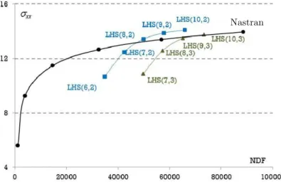
Figure 1 shows the structure and three meshes used in the analyses. Figure 2 to 4 present the
convergence under p-refinement for the maximum σxx tension found at the first 0 ply, where σxx is
Figure 1: Plate with circular hole: 44 × 3, 56 × 3 and 62 × 3 element meshes (meshes 1, 2 and 3, respectively).
Figure 2: Convergence of the maximum σxx under p-refinement at 0 ply for mesh 1.
Figure 3: Convergence of the maximum σxx under p-refinement at 0 ply for mesh 2. Nastran
Figure 4: Convergence of the maximum σxx under p-refinement at 0 ply for mesh 3.
Layer 0 Layer 90
Mesh Nastran LHS(10,2) Diff. Nastran LHS(9,2) Diff.
1 14.07 -0.86% 0.5074 8.90%
2 13.95 14.09 -1.00% 0.557 0.5080 8.80%
3 14.35 -2.87% 0.5265 5.48%
Table 1: Maximum σxx for the laminate [0o/90o/0o].
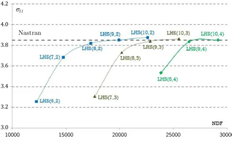
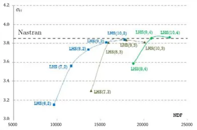
Figures 5 to 7 present the convergence of the maximum σ11 tension on the fiber direction for
mesh 1, 2 and 3 when the laminate is replaced by [45o]3. Relevant results of convergence for this
analysis are summarized in Table 2.
Figure 5: Convergence of the maximum σ11 under p-refinement at 45 ply for mesh 1.
Nastran
Nastran
10000 15000 20000 25000 30000
.
.
.
.
.
.
Figure 6: Convergence of the maximum σ11 under p-refinement at 45ply for mesh 2.
Figure 7: Convergence of the maximum σ11 under p-refinement at 45 ply for mesh 3.
Mesh Nastran LHS(9,2) Diff.
1 3.839 0.29%
2 3.85 3.852 -0.05%
3 3.865 -0.39%
Table 2: Maximum σ11 on the fiber direction for the laminate [45]3.
Results with the Nastran laminated element are also shown for the plate composed of both lam-inates. Even for simple meshes, the LHS elements have presented good convergence patterns.
4.2 Cracked Plate
In this test, the stress intensity factor K is evaluated for a cracked plate. The orthotropic plate has
thickness h = 1, height H = 10h, length L = 15h and one straight crack of length a = 0.5H. The
Nastran
Nastran
5000 10000 15000 20000 25000
10000 15000 20000 25000 30000 35000 .
.
.
.
.
.
. .
.
.
.
.
.
left edge is fixed and the right one is submitted to the action of a uniformly distributed load qx = 1 (force/area), as shown in Fig. 8.
The stress intensity factor in a state of plane stress can be calculated by
= ,
I
K EG (25)
where the strain energy release rate
– 
= 
G
h a (26)
has the derivative ∂ /∂a numerically replaced by the ratio between the strain energy change Δ
and the small value Δa assigned to the crack extension. In the present finite element formulation,
the strain energy is evaluated from
X FX
= T (27)
in which F refers to the assembled equation that comes from each element contribution (19) and X
results from the equation solution (23).
The 48-element mesh used in the analysis is illustrated in Figure 8. The strain energy evaluated
under p-refinement is presented in Figure 9 and the stress intensity factor is summarized in Table 3.
Figure 8: Cracked plate and 48 element mesh.
a Nastran LHS(10,2) LHS(10,3) LHS(10,4)
0.5H 4.34 4.30 4.45 4.49
Table 3: Stress intensity fator.
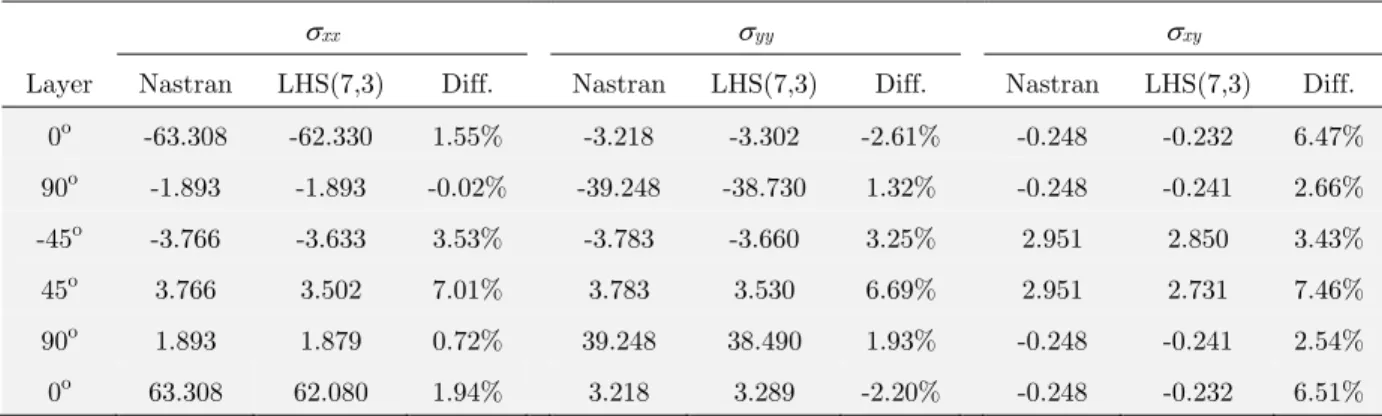
4.3 Nonsymmetric Laminated Plate
Bussamra et al. (2011) presented good results for the analysis of cross-ply laminate using Quasi-Trefftz element. In order to expand the application of the element, a nonsymmetric laminated plate is analyzed.
The structure showed in Figure 10 is a 6-layer [0o/90o/45o/–45o/90o/0o] laminated clamped
square plate, with side length L = 1 and thickness h = 0.06L, subject to a uniformly distributed
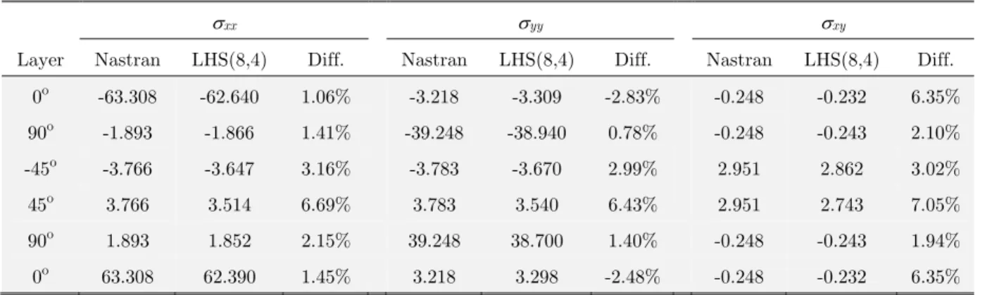
transverse load qx (force/area). A 5×5×6 element mesh is used in LHS tests. Tables 4 and 5 show
for the middle of each layer stresses at x = y = L/2 using LHS(7,3) and LHS(8,4) elements,
respec-tively.
Figure 10: Nonsymmetric laminated plate.
xx yy xy
Layer Nastran LHS(7,3) Diff. Nastran LHS(7,3) Diff. Nastran LHS(7,3) Diff. 0o -63.308 -62.330 1.55% -3.218 -3.302 -2.61% -0.248 -0.232 6.47%
90o -1.893 -1.893 -0.02% -39.248 -38.730 1.32% -0.248 -0.241 2.66% -45o -3.766 -3.633 3.53% -3.783 -3.660 3.25% 2.951 2.850 3.43%
45o 3.766 3.502 7.01% 3.783 3.530 6.69% 2.951 2.731 7.46% 90o 1.893 1.879 0.72% 39.248 38.490 1.93% -0.248 -0.241 2.54%
0o 63.308 62.080 1.94% 3.218 3.289 -2.20% -0.248 -0.232 6.51%
xx yy xy
Layer Nastran LHS(8,4) Diff. Nastran LHS(8,4) Diff. Nastran LHS(8,4) Diff. 0o -63.308 -62.640 1.06% -3.218 -3.309 -2.83% -0.248 -0.232 6.35% 90o -1.893 -1.866 1.41% -39.248 -38.940 0.78% -0.248 -0.243 2.10% -45o -3.766 -3.647 3.16% -3.783 -3.670 2.99% 2.951 2.862 3.02% 45o 3.766 3.514 6.69% 3.783 3.540 6.43% 2.951 2.743 7.05% 90o 1.893 1.852 2.15% 39.248 38.700 1.40% -0.248 -0.243 1.94% 0o 63.308 62.390 1.45% 3.218 3.298 -2.48% -0.248 -0.232 6.35%
Table 5: Stresses at the middle of each layer at the plate center for element LHS(8,4).
4.4 Membrane-Bending Coupling
The membrane-bending coupling behavior is tested in a square plate, with side length L = 1. The
left edge is fixed and the right one is submitted to the action of a uniformly distributed load qx =
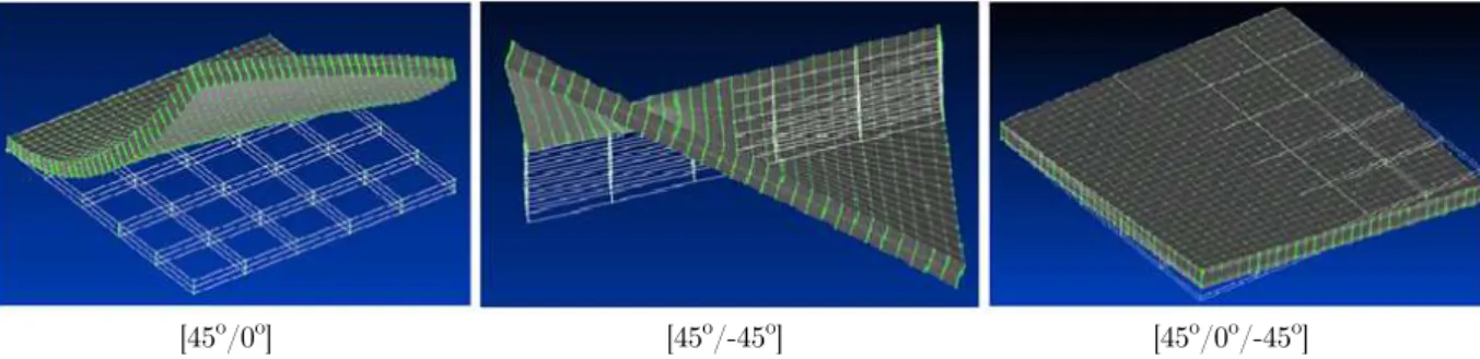
1(force/area). Three different stacking sequences for this structure were analyzed: 2-layer [0o/45o],
2-layer [45o/–45o], both with thickness [0.02/0.02], and 3-layer [45o/0o/–45o], with thickness
[0.01/0.02/0.01].
In this test, the deformed shapes of the plates are analyzed. To evaluate h-refinement, the
qua-si-Trefftz elements are used in two different meshes, with 9 and 25 elements per ply (meshes 1 and
2, respectively), as depicted in Figure 11. The origin of the global coordinate system xyz is on the
plate bottom surface.
Figure 11: Laminate and meshes.
Convergence of the transverse displacement at the free corner x = 1, y = 0, z = 0.02 using
Laminate Mesh Nastran LHS (10,2) Diff
[0o/45o] 1 6.990 6.651 4.85%
2 7.010 -0.29%
[45o/-45o] 1 3.213 2.936 8.62%
2 3.235 -0.68%
[45o/0o/-45o] 1 0.390 0.367 5.90%
2 0.401 -2.82%
Table 6: Transverse displacement at x = 1, y = 0, z = 0.02.
[45o/0o] [45o/-45o] [45o/0o/-45o]
Figure 12: Deformed shapes of the plates with membrane-bending coupling.
Figure 13: Convergence of transverse displacement for the laminate [0o/45o]. Nastran
10000 14000 18000 22000
.
.
.
.
Figure 14: Convergence of transverse displacement for the laminate [45o/-45o].
Figure 15: Convergence of transverse displacement for the laminate [45o/ 0 o/-45o].
Figure 16:
xx across the thickness at the plate center for the laminate [0o/45o]. NastranNastran
–
12000 16000 20000 24000 28000 32000 36000 10000 14000 18000 22000
.
.
– .
.
.
.
.
. .
.
.
.
Figure 17:
yy across the thickness at the plate center for the laminate [0o/45o].Figure 18:
xy across the thickness at the plate center for the laminate [0o/45o].
– . .
– . .
.
.
– . .
.
– . .
.
Figure 20:
yy across the thickness at the plate center for the laminate [45o/-45o].Figure 21:
xy across the thickness at the plate center for the laminate [45o/-45o].Figure 22:
xx across the thickness at the plate center for the laminate [45o/0o/-45o].– –
.
.
– . .
.
– .
.
.
Figure 23:
yy across the thickness at the plate center for the laminate [45o/0o/-45o].Figure 24:
xy across the thickness at the plate center for the laminate [45o/0o/-45o].5 CONCLUSIONS
The results reported in this paper clearly illustrate the efficiency of the three-dimensional model of the hybrid quasi-Trefftz stress finite element formulation in the solution of laminated plates. Many degrees of freedom are involved, but substantial memory and computing time are saved in the as-semblage and problem solution by taking numerical advantage of the high sparsity. Accurate esti-mates for stress concentration factors and stress intensity factors in plates with geometric disconti-nuities are found. The tests reported also show that the element can produce good estimates for both stresses and displacements in plane stress and plate membrane-bending coupling problems. Although good convergence rates are observed even for coarse meshes around the discontinuities,
the p-refinement procedure is still restricted to a complete polynomial stress basis of sixth degree.
Research on the extension of this basis is being developed to fully exploit the hierarchical nature of – . .
– . . .
.
– .
.
.
Acknowledgment
This work has been partially supported by Conselho Nacional de Desenvolvimento Científico e Tecnológico (CNPq).
Funding
Conselho Nacional de Desenvolvimento Científico e Tecnológico (CNPq).
Nomenclature
a Crack length b Body force
D, D* Differential operator, and its adjoint Ei Young’s moduli
Gij Shear moduli
k Material stiffness matrix K Stress intensity factor
ns, nz Number of stress and displacement modes N Unit outward normal vector matrix q Displacement weights
qx Uniform load (force/area) in x direction r Position vector
S Stress basis for σ
tΓ Specified surface traction u Displacement vector in V ũ Displacement vector on Γi andΓσ uΓ Specified surface displacements U Displacement basis for u
Strain energy
V Domain of an element X Stress weights
Z Displacement basis for ũ
Γ Boundary of an element
Γi, Γu, Γσ Interelement, kinematic and static boundaries ε Vector with strain components
Ζ Degree of the polynomial displacement ũ νij Poisson’s ratios
Ξ Local coordinate system
σ, σr Vectors with stress and residual stress components
ϕ Scalar harmonic displacement potentials ψ Vector harmonic displacement potentials
References
Bathe, K.J. (1996). Finite Element Procedures. Prentice Hall, Englewood Cliffs.
Bussamra, F.L.S., Lucena Neto, E., Ponciano, W.M. (2014). Simulation of stress concentration problems by hexahe-dral hybrid-Trefftz finite element models. Computer Modeling in Engineering & Sciences, 99(3): 255-272.
Bussamra, F.L.S., Lucena Neto, E., Raimundo Jr., D.S. (2012). Hybrid quasi-Trefftz 3-D finite elements for laminat-ed composite plates, Computers and Structures. 92-93:185-192.
Bussamra, F.L.S., Pimenta, P.M., Freitas, J.A.T. (2001). Hybrid-Trefftz stress elements for three-dimensional elasto-plasticity. Computer Assisted Mechanics and Engineering Sciences, 8: 235-246.
Cook, R.D., Malkus, D.S., Plesha, M.E., Witt R.J. (2002). Concepts and Applications of Finite Element Analysis. John Wiley, New York.
Freitas, J.A.T., Bussamra, F.L.S. (2000). Three-dimensional hybrid-Trefftz stress elements. International Journal for Numerical Methods in Engineering, 47(5): 927-950.
Freitas, J.A.T., Ji, Z.Y. (1996). Hybrid-Trefftz finite element formulation for simulation of singular stress fields. International Journal for Numerical Methods in Engineering, 39(2), 281-308.
Fung, Y.C., Tong, P. (2001). Classical and Computational Solid Mechanics, World Scientific, Singapore.
Jin, W.G., Sheng, N., Sze, K.Y., Li, J. (2005). Trefftz indirect methods for plane piezoelectricity. International Jour-nal for Numerical Methods in Engineering, 63(1): 139-158.
Qin, Q.H. (2003). Variational formulations for TFEM of piezoelectricity. International Journal of Solids and Struc-tures, 40(23): 6335-6346.

![Figure 16: xx across the thickness at the plate center for the laminate [0 o /45 o ]](https://thumb-eu.123doks.com/thumbv2/123dok_br/18886428.423947/13.808.212.539.716.983/figure-xx-thickness-plate-center-laminate-o-o.webp)
![Figure 17: yy across the thickness at the plate center for the laminate [0 o /45 o ]](https://thumb-eu.123doks.com/thumbv2/123dok_br/18886428.423947/14.808.263.586.86.323/figure-yy-thickness-plate-center-laminate-o-o.webp)
![Figure 22: xx across the thickness at the plate center for the laminate [45 o /0 o /-45 o ].](https://thumb-eu.123doks.com/thumbv2/123dok_br/18886428.423947/15.808.174.570.711.976/figure-xx-thickness-plate-center-laminate-o-o.webp)
