Abstract
In this paper, non-linear dynamics analysis of functionally graded material (FGM) shell structures is investigated using the higher order solid-shell element based on the Enhanced Assumed Strain (EAS). With this element, a quadratic distribution of the shear stress through the thickness is considered in an enhancing part. Material properties of the shell structure are varied continuously in the thickness direction according to the general four-parameter power-law distribution in terms of the volume fractions of the constituents. Performance and accuracy of the present higher order solid-shell element are confirmed by comparing the numeri-cal results obtained from finite element analyses with results from the literature.
Keywords
Non-linear dynamics, Higher Order Shear Deformation, Shear locking, Solid-shell element, FGM.
Nonlinear Dynamics Analysis of FGM Shell Structures with
a Higher Order Shear Strain Enhanced Solid-Shell Element
1 INTRODUCTION
In the last decades, functionally graded materials (FGM) are becoming more widely used since they provide many advantages to structural designers. FGMs shell structures are widely used in aircraft and space systems due to their advantages of high stiffness and their high heat-resistance. In an FGM, the structure is prepared from a mixture of ceramic and metal, or a combination of other metals or other ceramics that are appropriate to achieve the desired objective. Material properties of
A. Hajlaoui a E. Triki a A. Frikha a M. Wali a F. Dammak a
a Mechanical Modeling and
Manufactur-ing Laboratory (LA2MP), National En-gineering School of Sfax, B.P W3038, Sfax, University of Sfax, Tunisia [email protected]; [email protected];
[email protected]; [email protected];
http://dx.doi.org/10.1590/1679-78253323
FGMs are varied continuously in one or more directions. Therefore, the stress distributions are smooth hence interface problems are eliminated when compared to laminate structure
In order to avoid structural failure caused by dynamic loadings, linear dynamic characteristics of FGMs shell structures have been considered by many researchers. Finding analytic solutions for linear and non-linear dynamics analysis of functionally graded material is a very difficult task, and they only exist for particular cases. Meanwhile, the finite-element (FE) method has become the most widely used technique to model the processes of dynamics analysis.
There are several solution formulations for vibration and linear dynamic analysis of FGM shells structures. They can be classified into two groups: the 2D plate and shell models and the full 3D elasticity model. Zhi-Yuan and Hua-Ning (2007) studied free vibration characteristics of functionally graded cylindrical shells with holes using Kirchhoff Classical thin Plate Theory (CPT). On the other hand, Kadoli and Ganesan (2006) studied the buckling and free vibration analysis of functionally graded cylindrical shells subjected to a temperature-specified boundary condition. In their analysis, the finite element equations based on the First order Shear Deformation Theory (FSDT) and the Plane Stress Assumption (PSA) were formulated. Recently, Ansari et al. (2016) developed a non-classical size-dependent plate model based on the modified strain gradient and the FSDT for the bending, buckling and free vibration analyses of microscale FG plates.
Based on the Third order Shear Deformation Theory (TSDT) and PSA, Reddy (2000) present-ed a theoretical formulation, Navier's solutions of rectangular plates, and finite element models to study the nonlinear dynamic response of FGM plates subjected to a suddenly applied uniform pres-sure. Yang and Shen (2002) analyzed free and forced vibration for initially stressed FGM plates. In this contribution, theoretical formulations are based on TSDT and PSA including the thermal ef-fects. One-dimensional differential quadrature technique and Galerkin approach are used to deter-mine the transient response of the plate subjected to dynamic loads. Gharooni and Ghannad (2015) investigated displacements and stresses in pressurized thick FGM cylinders with exponential varia-tion of material properties based on TSDT. Furthermore, based on a TSDT of shells and PSA, Wali et al. (2015) Frikha et al. (2016) and Frikha et al. (2017) studied respectively the free vibration, linear dynamic response and fully geometrical nonlinear mechanical response of FGM shell struc-tures using an efficient double directors shell element proposed in Wali et al. (2014). The shear stress boundary conditions on top and bottom faces are considered in a discrete form as given in (2005).
For full 3D elasticity formulations for vibration and linear dynamic analysis of FGM shells, one find the work of Vel and Batra (2004) based on three dimensional exact solutions for free and forced vibrations of simply supported FGM rectangular plates. In Asemi et al. (2014) the static and dy-namic analyses of FGM skew plates are obtained based on the three-dimensional theory of elastici-ty. Graded elements, the principle of minimum energy and Rayleigh-Ritz energy method are used. Using 3D elasticity model, Nguyen and Nguyen-Xuan (2015) proposed an efficiently computational tool based on an isogeometric finite element formulation for static and dynamic response analysis of FGM plates.
Based on the CPT assumption and von-Karman geometrical nonlinearity, Woo et al. (2006) in-vestigated the nonlinear free vibration behavior of FGM plates. Allahverdizadeh et al. (2008) evalu-ated the material properties of an FGM thin circular plate and investigevalu-ated the nonlinear free and forced vibrations using the shooting technique. The formulation is based on CPT and von-Karman geometrical nonlinearity. Alijani et al. (2011) studied the nonlinear vibrations of FGM doubly curved shallow shells. They considered the thermal effect, the CPT assumption and Donnell nonlin-earity. Using the CPT with an improved Donnell equations and PSA, Bich and Nguyen (2012) ex-amined the nonlinear vibration of functionally graded circular cylindrical shells. Considering the CPT with PSA and von-Karman geometrical nonlinearity, Duc (2013) presented an analytic inves-tigation on the nonlinear dynamic response of eccentrically stiffened functionally graded double curved shallow shells resting on elastic foundations and being subjected to axial compressive load and transverse load. Using the same considerations, Duc and Cong (2015) investigated the nonlinear dynamic response of imperfect symmetrical thin FGM plate on elastic foundation.
Using the FSDT plate finite element method with PSA employing von-Karman nonlinearity, Praveen and Reddy (1998) investigated the nonlinear transient thermo-elastic response of FGM plates. Liew et al. (2006) studied the nonlinear vibration of a coating-FGM-substrate cylindrical panel subjected to a temperature gradient. The FSDT is considered with PSA and von-Karman geometrical nonlinearity. Also based on the FSDT with PSA and von-Karman geometrical nonline-arity, Zhang et al. (2012) analyzed the nonlinear dynamics of a clamped–clamped FGM circular cylindrical shell subjected to an external excitation and uniform temperature change.
Based on TSDT and PSA, Hao et al. (2008) presented an analysis of the nonlinear dynamics of a simply supported FGM rectangular plate subjected to the transversal and in-plane excitations in a thermal environment. The von-Karman geometrical nonlinearity assumption is used. Using the same von-Karman geometrical nonlinearity with TSDT and PSA, Duc et al. (2015) presented an analytical approach to investigate the nonlinear dynamic response and vibration of imperfect FGM thick circular cylindrical shells surrounded on elastic foundation. Based on TSDT with PSA and von-Karman type nonlinear kinematics, Liu et al. (2015) presented a nonlinear dynamic analysis of a slightly initial imperfect FGM circular cylindrical shell subjected to complex loads including aero-dynamic pressure and thermal loading.
It can be seen from the previous literature that in most of the studies, full 3D elasticity formu-lations are only limited to linear dynamic and free vibration of FGM structures. Also, the von-Karman or Donell geometrical nonlinearity are the only kinematic that has been basically used for the nonlinear dynamic analysis of shell’s structures where the PSA is largely considered.
The remainder of this paper is organized as follows. Functionally graded materials are described in section two. After that, solid-shell finite element formulation and a transient analysis of the non-linear formulation is described in section three and four respectively. Numerical results and discus-sions of the finite element model are investigated in detail in section five. Finally, some concluding remarks are analyzed and presented in section six.
2 FUNCTIONALLY GRADED MATERIALS
In this paper, we consider an FGM shell structures made from a mixture of metal and ceramics and the composition varies continuously in the thickness direction. In fact, the Young’s modulus E z( ), density r( )z and Poisson’s ratio n
( )
z are assumed to vary through the shell thicknesses accordingto a power-law distribution as
( ) (
z Ec Em)
Vc EmE
= - + ,r
( ) (
z =r
c -r
m)
Vc +r
m, n( ) (
z = nc -nm)
Vc +nm (1)in which the subscripts m and c refer to metal and ceramic components, respectively. In addition,
the volume fraction Vc follows two general four-parameter power-law distributions, Su et al. (2014).
(
, , , p)
IFGM a b c :
( )
1 1 12 2
p c c
z z
z a b
h h
V
é æ ö æ ö ù
ê ç ÷ ç ÷ ú
=êê - èçç + ÷ +÷÷ø ççè + ÷÷÷ø úú
ë û
(2)
(
, , , p)
IIFGM a b c :
( )
1 1 12 2
p c c
z z
z a b
h h
V
=êêéê - çççèæ - ÷ +÷øö÷÷ çèæçç - ÷÷÷÷öø úúùúë û
(3)
where a, b and c are the parameters which determine the material variation profile through the FGM shell thickness and p is the power-law index.
3 SOLID-SHELL FINITE ELEMENT FORMULATION
The developed solid-shell element is an eight nodes hexahedral element with three degrees of free-dom per node. The transverse shear strain is composed of two parts. The first one is independent of the thickness coordinate and formulated by the assumed natural strain method (ANS). The second part is an enhancing part, which ensures a quadratic distribution through the thickness.
The enhanced assumed strain method consists in the enhancement of the compatible part of the Green Lagrange strain tensor,
E
c, with an enhanced partE
to have a total strain as followsc
=
+
E
E
E
(4)3.1 Variational Formulation
(
, ,)
(
)
: . . 0 fc
V S
V y dV V dV ¶V dA
é ù
P u E S =
ò
ëê E +E -S E ûú -ò
F u -ò
F u = (5)where y is the strain energy function and u, E and S are the independent tonsorial quantities
which are: displacement, enhanced assumed strain and assumed stress fields respectively. Also in Eq. (5) appear the prescribed body force FV and surface traction FS. The orthogonality between
the enhanced strain and stress fields leads to
: 0
V dV =
ò
S E (6)This orthogonality condition reduce the number of independent variables in the original func-tional to just two
(
u E,)
. The weak form of this modified reduced functional may be obtained with the direction derivative leading to(
,)
:(
)
. . 0f c
V S
V V V
W d d d dV d dV d dA
= P =
ò
+ -ò
-ò
=u E S E E F u F u (7)
where S is the Piola-Kirchhoff stress tensor
y ¶ =
S
E (8)
3.2 Finite Element Formulation
In each finite element domain, an eight-node hexahedral solid-shell element is considered. The posi-tion vectors in reference and current configuraposi-tions respectively are
n =
X N X , x=N xn (9)
where N is the tri-linear shape functions matrix given by
1 3 2 3 3 3 4 3 5 3 6 3 7 3 8 3
N N N N N N N N
é ù
= êë úû
N I I I I I I I I (10)
n
x and Xn are nodal coordinates. The displacement field, with the corresponding variation and
increment, is interpolated in the same manner as follows
n =
u N U , du=N Ud n , D =u NDUn (11)
where Un = ëéu v w1, ,1 1,... , ,u v w8 8 8ùûT is the nodal displacements vector at the element level. The
co-variant base vectors obtained by partial derivative of the position vectors with respect to convective coordinate ξ =
(
x x x1, ,2 3) (
= x h z, ,)
in reference and current configuration are given byk k x ¶ =
X
G , k
k x ¶ =
x
The covariant metric tensor at a material point ξ, in the reference and current configuration are defined by
.
i j
é ù
= ë û
G G G , g= ëég gi. jûù , i j, =1,2, 3 (13)
This leads to the following Green-Lagrangean strain tensor
(
)
1 2
=
-E g G , 1
(
)
2
ij ij ij
E = g -G (14)
3.3 Compatible Strains
To treat the transverse shear locking and transverse normal locking problems, the ANS method is used. For the transverse shear strains, E13c and
23 c
E , the ANS method, proposed by Bathe and
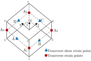
Dvorkin(1985), is used and evaluated at four mid-points of the element edgesA = (-1,0,0), B = (0,-1,0), C = (1,0,0), D = (0,(0,-1,0), Fig. 1.
Figure 1: Transverse shear strain and thickness strain interpolation points.
The transverse shear strains are given by
(
)
(
)
(
)
(
)
(
)
(
13 13)
(
)
(
13 13)
13
23 13 13 13 13
1 1
1
2 1 1
B B D D
c
c A A C C
g G g G
E
E g G g G
h h
x x
é ù
é ù - - + +
-ê ú
ê ú = ê
ú
ê ú - - + +
-ê ú
ê ú
ë û ë û (15)
However, for the thickness strains, 33c
E
, we adopt the ANS method as in Klinkel et al. (1999),Vu-Quoc and Tan (2003) and Hajlaoui et al. (2012, 2015, 2016) and evaluated at four collocation points defined in the reference surface
(
z =0)
: A1=(-1,-1,0), A2=(1,-1,0), A3=(1,1,0), A4=(-1,1,0), Fig. 1. The thickness strains is given byA1
A2 A3
A4
C D
A
B 8
7
6
2 3
4
1 5
ξ η ζ
(
)(
)
(
)
4
33 33 33
1
1 1
4 1 1 2
c L L
L L
L
E xx hh g G
=
=
å
+ + - (16)For the detailed description of the ANS method, refer to Hajlaoui et al. (2012, 2015, 2016). The compatible part is arranged in (6x1) column matrix as follows
11 22 33 2 12 2 13 2 23
T c éEc Ec Ec Ec Ec Ec ù
= êë úû
E (17)
Using Eqs. (15)-(17) and approximations Eqs. (9) and (11), the virtual and incremental compat-ible Green Lagrange strain tensor are then given by
c
n
dE =B Ud , DEc = DB Un (18)
where B is the strain interpolation matrix, associated to node I
(
I =1, 8)
and denoted BI is givenby
(
)(
)
(
)
(
)
(
)
(
)
(
)
(
)
(
)
(
)
1 ,1 2 ,2 4 1 3 ,3 4 12 ,1 1 ,2
1
3 ,1 1 ,3 3 ,1 1 ,3
2 1
3 ,2 2 ,3 3 ,2 2 ,3
2
N N
1 1 N
N N
1 N N 1 N N
1 N N 1 N N
T
T T T T
T T T T
T I T
I
L L
L L I
T
L I
T T
I I
B B B B D D D D
I I I I
A A A A C C C C
I I I I
x x h h
h h x x -= é ù ê ú ê ú ê ú ê ú ê ú
ê + + ú
ê ú
= ê ú
ê + ú
ê ú
ê é - + + + + ùú
ê êë úûú
ê é ùú
ê ê - + + + + úú
êë ë û û
å
g g g B T g gg g g g
g g g g ú
(19)
Matrix T, in Eq. (19), is the transformation of the strain tensor from parametric coordinates to the local Cartesian coordinates, written as
( ) ( ) ( )
( ) ( ) ( )
( ) ( ) ( )
2 2 2
11 21 31 11 21 11 31 21 31
2 2 2
12 22 32 12 22 12 32 22 32
2 2 2
13 23 33 13 23 13 33 23 33
11 12 21 22 31 32 11 22 12 21 11 32 12 31 21 32 22 31
11 13 21 23 31 33 11 23 13 21 11 33 13
2 2 2
2 2 2
2 2 2
t t t t t t t t t
t t t t t t t t t
t t t t t t t t t
t t t t t t t t t t t t t t t t t t
t t t t t t t t t t t t t t
=
+ + +
+ +
T
31 21 33 23 31
12 13 22 23 32 33 12 23 13 22 12 33 13 32 22 33 23 32
t t t t
t t t t t t t t t t t t t t t t t t
é ù ê ú ê ú ê ú ê ú ê ú ê ú ê ú ê ú ê ú
ê + ú
ê ú
ê + + + ú
ê ú
ë û
(20)
where tij =G Ti. j and Tj (j = 1, 2, 3) are a local orthonormal base vectors.
3.4 Enhanced Strains
The enhanced Green-Lagrange strain part is related to the internal strain parameters vector α as:
=
where
E
, dE
and DE
are total, virtual and incremental enhanced Green Lagrange strain tensor respectively. The crucial assumption of the EAS method is the enforcement of the orthogonality conditions for the assumed stress field S and the enhanced strainE
. This orthogonality conditionsimpose the following choice for the interpolation function matrix M to be expressed as follows
0 0 det det T xhz -= J
M T M
J
, 1 1 1
1 1 1 xhzd d dx h z 0
- - - =
ò ò ò
M (22)where the subscript ‘0’ means the evaluation at the center of the element in the natural coordinates and J= êéëG G G1, 2, 3ùúû is the Jacobian matrix. Eq. (22) responds a minimum requirement that the
enhancing strain be orthogonal to the constant stress state. The interpolation matrix Mxhz, in Eq.
(22), is expression in term of the parametric coordinates
(
x h z, ,)
. Three choices of matrix Mxhz can be considered with, 7, 9 and 11 parameters7
2
2
0 0 0 0 0 0
0 0 0 0 0 0
0 0 0 0 0 0
0 0 0 0 0
1
0 0 0 0 0 0
5
1 0 0 0 0 0 0
5 xhz x h z x h z z æ ö÷ ç ÷ ç ÷ ç ÷ ç ÷ ç ÷ ç ÷÷ ç ÷ ç ÷ ç ÷ ç ÷ ç ÷
= çç ÷÷
ç ÷÷
ç ÷
ç - ÷
ç ÷
ç ÷
ç ÷
ç ÷
ç ÷
ç - ÷÷
ç ÷ çè ø M (23.a) 9 2 2
0 0 0 0 0 0 0 0
0 0 0 0 0 0 0 0
0 0 0 0 0 0
0 0 0 0 0 0 0
1
0 0 0 0 0 0 0 0
5
1
0 0 0 0 0 0 0 0
5 xhz
x h
z xz hz
x h z z æ ö÷ ç ÷ ç ÷ ç ÷ ç ÷ ç ÷ ç ÷÷ ç ÷ ç ÷ ç ÷ ç ÷ ç ÷
= çç ÷÷
ç ÷÷
ç ÷
ç - ÷
ç ÷
ç ÷
ç ÷
ç ÷
ç ÷
ç - ÷÷
ç ÷ çè ø M (23.b) 2 2 11
0 0 0 0 0 0 0 0 0
0 0 0 0 0 0 0 0 0
0 0 0 0 0 0 0 0
0 0 0 0 0 0 0 0 0
1
0 0 0 0 0 0 0 0 0 0
5
1
0 0 0 0 0 0 0 0 0 0
5
xhz
x xh
h xh
z xz hz
x h z z = -æ ö÷ ç ÷ ç ÷ ç ÷ ç ÷ ç ÷ ç ÷÷ ç ÷ ç ÷ ç ÷ ç ÷ ç ÷ ç ÷ ç ÷ ç ÷÷ ç ÷ ç ÷ ç ÷ ç ÷ ç ÷ ç ÷ ç ÷ ç ÷÷ ç ÷ çè ø M (23.c)
In all these three matrices, the term 1 2
5 -z ensures the parabolic transverse shear distribution
How-ever, the three matrices are different in the plane and thickness strains enhancement. In a previous work, Hajlaoui et al. (2016), the analysis of stiffness matrix eigenvalue in the incompressible range demonstrate that only the 11 parameters solid shell element, Eq. (23.c), provided the correct eigen-values. As FGM materials are far from incompressible conditions as in rubber or elastoplasticity, and to reduce the computational time, one can choose the nine parameters, C3D8C9 element, which will be the only considered in the numerical results.
3.5 Linearization
With the finite element approximation, Eq. (18) and (21), at hand, the continuum weak form, Eq. (7), became in a discrete form as
(
int)
α .T T
n ext
W =dU f -f +d h (24)
where, fint, fext and h, are given by the following expressions
int
T
V dV
=
ò
f B S , dA
f
T T
ext =
ò
V VdV +ò
¶V Sf N F N F , T
V dV
=
ò
h M S (25)
Equation (24) is a nonlinear equation that will be solved iteratively by the Newton-Raphson method. For this purpose one need the corresponding linearization
(
)
L LH U int. , 0
T
n ext
T T
n n
W DW d d
æ é ùìïD üï é - ùö÷ çê úï ï
é ùç ê ú ÷
+ D D =ëê ûú êçç úíï D ýï+ê ú ÷÷= ÷ çèêë ú ïûî ïþ êë úûø
f f
K
U U
h
(26)
where L, H and K are given by
L T BdV
V
=
ò
M , H T dVV
=
ò
M M , K=KD +KG (27)with = ¶2y ¶ ¶E E
is the
6 6
three dimensional material tangent moduli, or elasticity tensor, andD
K is given by
T D
V dV
=
ò
K B B (28)
where the matrix B is given by Eq. (19) and KG is the geometric stiffness matrix
Δδ
T T T
n G n V dV
dU K DU =
ò
S Ec(29)
Relative to a couple of nodes (I, J) the matrix KG is given by
IJ
G =
ò
Vdiag Géêë IJ GIJ GIJùúûdV(
)(
)
(
)
(
)
(
)
(
)
(
)
(
)
(
)
(
)
,1 ,1 ,2 ,2 4 1 ,3 ,3 4 1,1 ,2 ,2 ,1 1
,1 ,3 ,3 ,1 ,1 ,3 ,3 ,1
2 1
,2 ,3 ,3 ,2 ,2 ,3 ,3 ,2
2
N N N N
1 1 N N
N N N N
1 N N N N 1 N N N N
1 N N N N 1 N N N N
I J I J
L L
L L I J
T T
L IJ
I J I J
B B B B D D D D
I J I J I J I J
A A A A C C C C
I J I J I J I J
G x x h h
h h x x -= é ù ê ê ê ê
ê + +
ê
= ê
ê +
ê
ê é ù
ê êë - + + + + úû
ê
ê é - + + + + ù
ê ê ú
ë ë û
å
S T ú ú ú ú ú ú ú ú ú ú ú ú ú úû (31)The strain parameters D must be eliminated from Eq. (26) at the element level, which leads to following element tangent operator KT and residual vector R
(
L HT 1L)
T D G
-= - +
K K K , L H 1h +
int T
ext
-=
-R f f (32)
4 TRANSIENT ANALYSIS OF THE NON-LINEAR FORMULATION
In order to extend the variational formulation, Eq. (24), to accommodate transient analysis, the body force is replaced by FV ¬FV -ru . Then, with this replacement the variational equation
became
(
int iner)
α .T T
n ext
W =dU f +f -f +d h , e T iner
V r dV =
ò
f N u (33)
The acceleration in Eq. (33) is computed from the isoparametric interpolation as in Eq. (11). Thus, the inertia term and residual vector may be written as
iner = n
f MU , + L H 1h
int T
ext n
-= -
-R f f MU (34)
where M is the consistent mass matrix. The Newmark method is a one-step method, which is used
to advance the solution from time tn to tn+1. Firstly, given the initial displacement and velocity
vectors, the initial acceleration is determined by solving Eq. (34). The Newmark formula to process the solution is given by
* 1
1 1
i i
TD n++ = n+
K U R , *
2 1
T T T
t t
g
b b
= + +
D D
K K C M (35)
with the updating formulas
1 1
1 1 1
i i i
n++ = n+ + D n++
U U U , 1 1
1 1 1
i i i
n n n
t g b
+ +
+ = + + D D +
U U U , 11 1 11
2 1
i i i
n n n
t b
+ +
+ = + + D +
D
U U U (36)
where 1 1
i n
+ + U , 1
1
i n
+ +
U , and 1
1
i n
+ +
U are displacement, velocity and acceleration vectors given in the initial
state by
0 1 n+ = n
U U , 0
1 1 1
2
n n t n
g g
b b
+
æ ö÷ æ ö÷
ç ç
=çç - ÷÷÷ + D çç - ÷÷÷
è ø è ø
U U U , 0 1 1 1 1
2 2
n n n
b b
+
æ ö÷ ç
= - +çç - ÷÷÷
è ø
The Newmark parameters b and gare chosen as b =0.25, g = 0.5.
5 NUMERICAL RESULTS AND DISCUSSION
The finite element formulation of the present higher order shear strain enhanced solid-shell element for nonlinear dynamic analyses of functionally graded material shell structures as presented in the previous sections. In this section, a comprehensive investigation concerning the nonlinear dynamic response of functionally graded material shell structures with various boundary conditions is given to demonstrate the accuracy and reliability of the present higher order solid-shell element.
5.1 Pull-Out of an Open-Ended Isotropic Cylindrical Shell
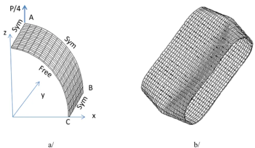
The purpose of this example is to demonstrate the ability of the formulation to capture large dis-placement and illustrate the robustness of the numerical implementation in static analysis. A short cylinder, with two pinching vertical forces at the middle section is modeled using one octant Fig. 2a.
a/ b/
Figure 2: Pull-out of an open-ended cylindrical shell a/ Finite element model, b/ Reel deformed configuration at P=40000.
This popular benchmark problem constitutes a severe test of shell finite element formulations and has been addressed in Sze et al. (2004) and Payette and Reddy (2014) among others. A 16x16 meshing is used for this validation test and applying the appropriate symmetry boundary condi-tions, Fig. 2.a. The length of the cylinder is L=10.35, the radius is R=4.953, and the thickness is h=
0.094. Material properties for this test are E =10.5 10´ 6, n =0.3125. The concentrated load
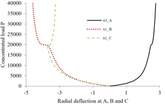
Figure 3: Pull-out force P vs. radial deflections at points A, B and C for the open-ended cylindrical shell.
The results shown in Figs. 3 are visually in unison with radial deflections for points A, B and C provided by Payette and Reddy (2014).
5.2. Shallow Spherical Cap Under a Concentrated Load
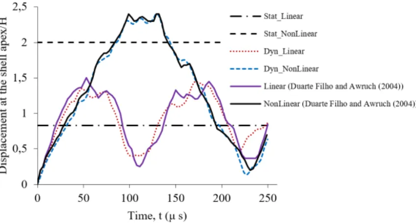
In this sub-section, we present numerical simulations in order to illustrate the good performance of the proposed formulation. The dynamic behavior of a clamped isotropic spherical shell under a con-centrated apex load, F=100, is presented. This test is proposed in Duarte Filho and Awruch (2004). Material and geometric properties for this test are E =107, n=0.3, r=0.000245, q=10.9,
R=4.76, and h = 0.01576. Loading and finite element mesh are shown in Fig.4.
Figure 4: Shallow spherical cap, geometry and finite element modeling.
Figure 5: Dynamic response of the isotropic shallow spherical cap.
5.3 FGM Plate Under Constant Distributed Load
This example consists on a square functionally graded plate subjected to a constant uniformly dis-tributed loading of q = -106N /m2. This numerical test has been addressed in Praveen and Reddy
(1998) among others. The side length or the plate is a=b=0.2m and the thickness h = 0.01m. The plate is made of the constituent materials: aluminum (bottom surface) and zirconia (top surface). Young’s modulus, Poisson’s ratio and density for the aluminum are Em =70GPa,
0.3
n = , r =2707kg/m3, and for zirconia are 151 c
E = GPa, n =0.3, r=3000kg/m3,
respec-tively. The used law distribution of the FGM plate is the classical power-law which can be obtained by the general four-parameter power-law distribution Eq. (3): FGMII
(
1, 0, , pc)
. By noting thesym-metry, only one quadrant of the plate is modeled with 8x8x1 elements. The time increment is
5
10
t -s
D = . The center deflection and time were non-dimensionalized according to the following expressions: center deflection /
( )
2m
w =w E h q a and time t =t Em /
(
a2rm)
.Figure 6: Temporal evolution of center deflection of simply supported FGM square plates under suddenly applied uniform load.
Figure 7: Temporal evolution of center deflection of clamped FGM square plates under suddenly applied uniform load.
5.4 Clamped Circular FGM Plate Under Distributed Transverse Load
This example, investigated in Nguyen and Nguyen-Xuan (2015), consists on clamped circular FGM plates under uniform pressure 106 N/m2. The radius is R=0.5 m and the thickness is h=0.1 m. The circular FGM plate is made of the same constituent materials as the previous example, Aluminum-Zirconia. The used law distribution of the FGM plate is the classical power-law which can be ob-tained by the general four-parameter power-law distribution Eq. (3): FGMII
(
1, 0, , pc)
. Usingsym-metry boundary conditions, one quadrant of the shell is modeled with 192 elements, Fig. 8. A time step of 10-5 s is used in this problem. The center deflection and time were non-dimensionalized ac-cording to the following expressions: center deflection . /
(
2)
m
w =w E h q R and time
(
2)
/
m m
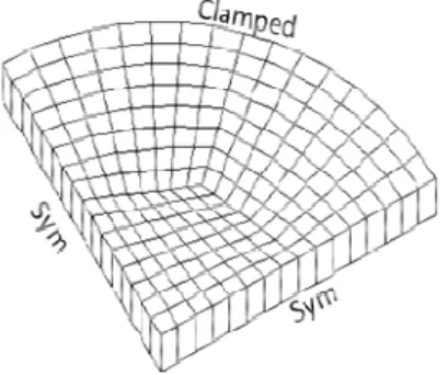
Figure 8: A quadrant of the clamped FGM circular plate modeled by 192 elements, 434 nodes.
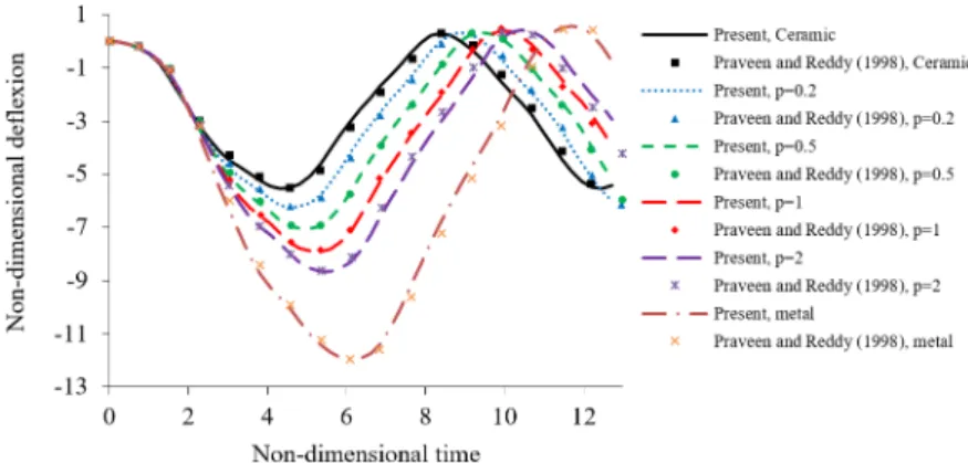
Fig. 9 illustrates the central deflection dynamic response of the clamped FGM circular plate. In this figure, ANSYS solutions, for full metal and full ceramic, using quadratic finite elements and approximately 140436 degrees of freedom, are given in Nguyen and Nguyen-Xuan (2015). The pre-sent solutions, using only 1302 degrees of freedom, match very well with the ones obtained using ANSYS software. In addition, Fig. 9 shows the results obtained using several values of the power low index, 0.2, 0.5, 1 and 2. The present results are in good agreement with the published ones giv-en in Nguygiv-en and Nguygiv-en-Xuan (2015) using 2535 degrees of freedom.
Figure 9: Temporal evolution of center deflection of clamped FGM circular plate under suddenly applied uniform load.
5.5 Simply Supported FGM Plate Under Varying Distributed Load
This numerical example consist on a simply supported square functionally graded plate of side length a=b=1m and thickness h = 0.01 m. The FGM plate is subjected to a uniformly distributed excited transverse load q t( )=Nsin(Wt). The FGM plate is made of the constituent materials:
alu-minum (bottom surface) and alumina (top surface). Young’s modulus, Poisson’s ratio and density for the aluminum are Em =70GPa, nm =0.3 and 2707 / 3
m kg m
380
c
E = GPa, nc =0.3 and 3800 / 3
c kg m
r = , respectively. The used law distribution of the FGM plate is the classical law which can be obtained by the general four-parameter power-law distribution Eq. (3): FGMII
(
1, 0, , pc)
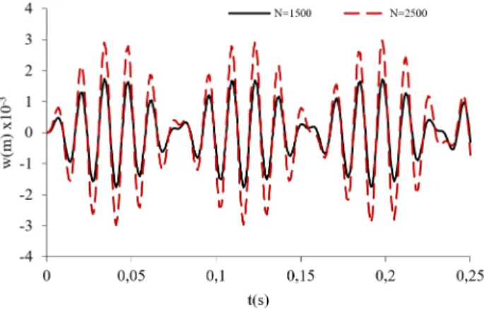
. This numerical problem is investigated in Duc and Cong (2015) with a sigmoid-FGM material. By noting the symmetry, only one quadrant of the plate is modeled with 8 x 8 x 1 elements. A time step of 10-3 s is used in this numerical test.Fig. 10.a shows the nonlinear dynamic response, represented by graph of maximum deflection (p=1, N=1500N/m², Ω= 500). In the same conditions Fig. 10.b shows the relation of maximum deflection and the velocity of maximum deflection.
Figure 10: Nonlinear dynamic response of the square FGM plate (a) maximum deflection versus time (b) velocity versus maximum deflection.
Figure 11: Nonlinear dynamic response of the square FGM plate under different loads.
Fig.11 shows the nonlinear response of the FGM square plate with different intensity of loads:
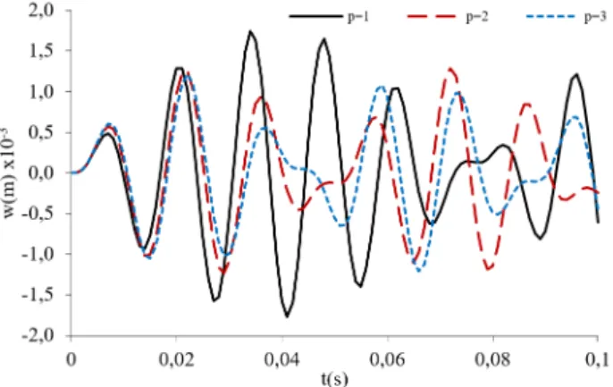
Figure 12 shows the nonlinear response of the FGM square plate with different power-law in-dex: p=1, p=2 and p=3; N=1500N/m², Ω= 500. From obtained results, one can see that ampli-tudes decrease, when increasing the power law index. This is because the plate is stiffened due to increasing the volume fraction index of the ceramic phase. The non-linear transient responses per-form the phenomenon like periodic cycles.
The results shown in Figs. 10, 11 and 12 are visually in unison with those provided by Duc and Cong (2015) using a sigmoid distribution instead of the present power low distribution.
Figure 12: Nonlinear dynamic response of the square FGM plate under different power-law index.
5.6 Non-Linear Dynamic Analyses of FGM Cylindrical Shells
This numerical example, examined in Bich and Nguyen (2012), consist on an FGM cylindrical shell with radius of curvature R, thickness h and length L subjected to an external pressure uniformly distributed on the surface of the shell q t( )=Nsin(Wt). Suppose that the material composition of the shell varies following a simple power law in terms of the volume fractions which can be deduced by the general four-parameter power-law distribution FGMII
(
1, 0, , pc)
. We consider the FGM cylin-drical shells composed of ZrO2 and Ti–6Al–4V with the material properties for ZrO2:154.3211
c
E = GPa, 5700 / 3
c kg m
r = , nc =0.298 and for Ti–6Al–4V: Em =105.6960GPa,
3
4429 /
m kg m
r = , nm =0.2981. Simply supported boundary conditions are considered at x=0
and x=L. By noting the symmetry, only one octant of the cylindrical shell is modeled with 16x16x1 elements.
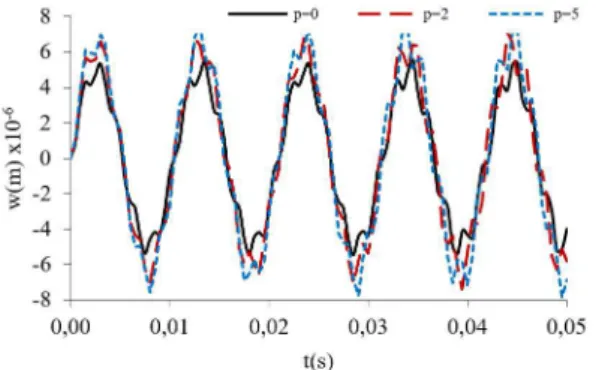
Fig. 13 illustrate the effect of the power law index p on the nonlinear dynamic response of ZrO2/Ti–6Al–4V FGM cylindrical shells with L/R =2, R/h =500 and q t( )=1500 sin(600 )t .
As remarked in previous test, the amplitude of the nonlinear dynamic of the FGM shells increases when increasing the power low index p.
Fig. 14 gives the effect of the thickness ration R/h on the nonlinear response of FGM cylindrical shell with L/R = 2, p =2 and q t( )=1500 sin(600 )t . As had been anticipated, the amplitude of
Figure 13: Effect of power law index p on the responses of FGM cylindrical shell.
Figure 14: Effect of ratio R/h on the responses of FGM cylindrical shell.
6 CONCLUSION
This paper presents a numerical investigation on the nonlinear dynamic response of FGM shell structures. Material properties of the shell structure are assumed to vary continuously through the thickness according to the general four-parameter power-law distribution in terms of the volume fractions of the constituents.
The finite element formulation is based on the higher order shear strain enhanced solid-shell el-ement. To avoid locking in the thin shell cases, the ANS method, for the transverse shear strains and thickness strain, is used instead of the continuum components in the compatible part of strain tensor. In the enhanced strain part, parabolic functions in terms of natural thickness coordinate are considered for the transverse shear strains. This permit to remove shear correction factors and im-proves the accuracy of transverse shear stresses. In addition, the enhancements of membrane part and the transverse strain are considered to avoid the in-plane bending and volumetric locking.
Results of the present formulations are verified by comparing the present results with those available in literatures. The obtained results show the effects of material, boundary conditions, exci-tation and geometrical parameters on the dynamical response of FGM structures. Thus, it is obvi-ous that the dynamic response of the considered FGM structures depends on many factors signifi-cantly: power low index, boundary conditions, excitation and geometrical parameters of the FGM structures.
In addition, the present higher order solid-shell model can be used in complex FGM or compo-site shell’s structures analysis, unlike the analytic formulation that can be employed only for smooth differentiable geometry of shell structures.
References
Alijani, F., Amabili, M., Karagiozis, K., Bakhtiari-Nejad, F., (2011). Nonlinear vibrations of functionally graded doubly curved shallow shells. Journal of Sound and Vibration 330:1432-1454.
Allahverdizadeh, A., Naei, MH., Nikkhah Bahrami, M., (2008). Nonlinear free and forced vibration analysis of thin circular functionally graded plates. Journal of Sound and Vibration 310:966-984.
Ansari, R., Hasrati, E., Shojaei, M. F., Gholami, R., Mohammadi, V., Shahabodini, A., (2016). Size-Dependent Bending, Buckling and Free Vibration Analyses of Microscale Functionally Graded Mindlin Plates Based on the Strain Gradient Elasticity Theory. Latin American Journal of Solids and Structures 13: 632-664
Asemi, K., Salami, S.J., Salehi, M., Sadighi, M., (2014). Dynamic and Static analysis of FGM Skew plates with 3D Elasticity based Graded Finite element Modeling. Latin American journal of Solids and Structures 11:504-533. Bathe, K.J., Dvorkin, E., (1985). A four-node plate bending element based on Mindlin/Reissner plate theory and a mixed interpolation. International Journal for Numerical Methods in Engineering 21:367-383.
Bich, DH., Nguyen, N.X., (2012). Nonlinear vibration of functionally graded circular cylindrical shells based on im-proved Donnell equations. Journal of Sound and Vibration 331:5488-5501.
Dammak, F., Abid, S., Gakwaya, A., Dhatt, G., (2005). A formulation of the non linear discrete Kirchhoff quadrilat-eral shell element with finite rotations and enhanced strains. Revue Européenne des Eléments Finis 14:7-31.
Duarte Filho, L.A., Awruch, A.M., (2004). Geometrically nonlinear static and dynamic analysis of shells and plates using the eight-node hexahedral element with one-point quadrature. Finite Elements in Analysis and Design 40:1297-1315. Duc, N.D., (2013). Nonlinear dynamic response of imperfect eccentrically stiffened FGM double curved shallow shells on elastic foundation. Composite Structures 99:88-96.
Duc, N.D., Cong, P.H., (2015). Nonlinear dynamic response of imperfect symmetric thin sigmoid-functionally graded material plate with metal-ceramic-metal layers on elastic foundation. Journal of Vibration and Control 21:637-646. Duc, N.D., Tuan, N.D., Tuan, P., Dao, N.T., Dat, N.T., (2015). Nonlinear dynamic analysis of sigmoid functionally graded circular cylindrical shells on elastic foundations using the third order shear deformation theory in thermal environments. International Journal of Mechanical Sciences 101-102:338-348.
Frikha, A., Dammak, F., (2017). Geometrically non-linear static analysis of functionally graded material shells with discrete double directors shell element. Computer Methods in Applied Mechanics and Engineering. 315:1-24.
Frikha, A., Wali, M., Hajlaoui, A., Dammak, F., (2016). Dynamic response of functionally graded material shells with a discrete double directors shell element.Composite Structures 154 :385–395.
Gharooni, H., Ghannad, M., (2015). Elastic analysis of pressurized thick FGM cylinders with exponential variation of material properties using TSDT. Latin American Journal of Solids and Structures 12 (6):1024-1041
Hajlaoui, A., Jarraya, A., Kallel-Kammoun, I., Dammak, F., (2012). Buckling analysis of a laminated composite plate with delaminations using the enhanced assumed strain solid shell element. Journal of Mechanical Science and Technology, 26:3213-3221.
Hajlaoui, A., Wali, M., Ben Jdidia, M., Dammak, F., (2016). An improved Enhanced Solid Shell Element for Static and Buckling Analysis of shell structures, Mechanics & Industry, 17:510.
Hao, Y.X., Chen, L.H., Zhang, W., Lei, J.G., (2008). Nonlinear oscillations, bifurcations and chaos of functionally graded materials plate. Journal of Sound and Vibration 312:862-892.
Kadoli, R., Ganesan, N., (2006). Buckling and free vibration analysis of functionally graded cylindrical shells subject-ed to a temperature-specifisubject-ed boundary condition. Journal of Sound and Vibration 289:450-480.
Klinkel, S., Gruttmann, F., Wagner, W., (1999). A continuum based three-dimensional shell element for laminated structures. Computers & Structures 71:43-62.
Liew, K.M., Yang, J., Wu, Y.F., (2006). Nonlinear vibration of a coating-FGM-substrate cylindrical panel subjected to a temperature gradient. Computer Methods in Applied Mechanics and Engineering 195:1007-1026.
Liu, Y.Z., Hao, Y.X., Zhang, W., Chen, J., Li, S.B., (2015). Nonlinear dynamics of initially imperfect functionally graded circular cylindrical shell under complex loads. Journal of Sound and Vibration 348:294-328.
Nguyen, K.D., Nguyen-Xuan, H., (2015). An isogeometric finite element approach for three-dimensional static and dynamic analysis of functionally graded material plate structures. Composite Structures 132:423-439
Payette, G.S., Reddy, J.N., (2014). A seven-parameter spectral/hp finite element formulation for isotropic, laminated composite and functionally graded shell structures. Computer methods in applied mechanics and engineering 278:664-704.
Praveen, G.N., Reddy, J.N., (1998). Nonlinear transient thermoelastic analysis of functionally graded ceramic-metal plates. International Journal of Solids and Structures 35:4457-4476.
Reddy, J.N., (2000). Analysis of functionally graded plates. International Journal for Numerical Methods in Engi-neering 47:663-684.
Su, Z., Jin, G., Shi, S., Ye, T., Jia, X., (2014). A unified solution for vibration analysis of functionally graded cylin-drical, conical shells and annular plates with general boundary conditions. International Journal of Mechanical Sci-ences 80:62-80.
Sze, K.Y., Liu, X.H., Lo, S.H., (2004). Popular benchmark problems for geometric nonlinear analysis of shells. Finite Elements in Analysis and Design 40:1551-1569.
Vel, SS., Batra, RC., (2004). Three dimensional exact solution for the vibration of FGM rectangular plates. Journal of Sound and Vibration 272:703-730.
Vu-Quoc, L., Tan, X.G., (2003). Optimal solid shells for non-linear analyses of multilayer composites. I. Stat-ics. Computer methods in applied mechanics and engineering 192:975-1016.
Wali, M., Hajlaoui, A., Dammak, F., (2014). Discrete double directors shell element for the functionally graded ma-terial shell structures analysis. Computer Methods in Applied Mechanics and Engineering 278:388-403.
Wali, M., Hentati, T., Jarraya, A., Dammak, F., (2015). Free vibration analysis of FGM shell structures with a discrete double directors shell element. Composite Structures 125:295-303.
Woo, J., Meguid, SA., Ong, LS., (2006). Nonlinear free vibration behavior of functionally graded plates. Journal of Sound and Vibration 289:595-611.
Yang, J., Shen, H.S., (2002). Vibration characteristic and transient response of shear-deformable functionally graded plates in thermal environments, Journal of Sound and Vibration, 255:579-602.
Zhang, W., Hao, Y.X., Yang, J., (2012). Nonlinear dynamics of FGM circular cylindrical shell with clamped–clamped edges. Composite Structures 94:1075-1086.