Comparison of Energy Storage Technologies for applications of
Unmanned Electrical Aerial Vehicles
INEGI
André Filipe Rosário de Brito Lhamas
Relatório do Projecto Final / Dissertação do MIEM
Orientador no INEGI: Dr. Nuno Correia; Eng. João Barbosa Orientador na FEUP: Prof. Dr. António Torres Marques
Faculdade de Engenharia da Universidade do Porto Mestrado Integrado em Engenharia Mecânica
Comparação de tecnologias de armazenamento de energia para aplicações de veículos aéreos não tripulados eléctricos (UEAV)
Resumo
O trabalho relatado nesta dissertação visou projectar a redução de massa numa célula de combustível de membrana de permuta iónica (PEM FC) através do uso de materiais compósitos nas placas terminais (end plates), como alternativa ao metal. Uma vez que as placas de terminais, assim como outros componentes de fixação, representam uma fracção significativa da massa global do sistema, esta redução resulta numa maior potência e energia específicas, podendo possivelmente tornar os sistemas PEM FC mais interessantes em aplicações onde o peso se apresenta como um factor crítico. Além da redução de massa, é também discutida a deformação na placa. Foi demonstrado na literatura que grandes deformações nas placas de terminais podem levar a influências negativas no desempenho da célula de combustível. Esta dissertação perspectiva soluções construtivas alternativas que são capazes de reduzir significativamente o peso, assim como alcançar valores de deformação mais baixos do que as placas de fim metálicas, aumentando assim a eficiência global do sistema.
O sistema de célula de combustível foi estudado para o caso de uma aeronave com 210 kg de peso máximo de descolagem (MTOW), possuindo um requisito de cerca de 20 kW de potência máxima. Neste caso, a massa disponível para o sistema propulsivo foi de 70 kg. Através do uso de uma análise por elementos finitos, o conceito com o melhor desempenho entre os conceitos sugeridos foi seleccionado. Posteriormente, foram realizados cálculos com vista à determinação da energia específica do sistema resultante. Dessa forma, tornou-se possível uma comparação com os conceitos de placas de fim actualmente usados. Além disso, foi também efectuada a comparação dos sistemas referidos com um sistema propulsivo convencional, compreendendo um motor de combustão interna (ICE).
O novo conceito de placa de fim permitiu um aumento significativo na energia específica (28,3%), ainda que tenha sido também provado a incapacidade actual de as células de combustível igualarem sistemas ICE convencionais, mesmo que, tal como é demonstrado, ter também provado que existe espaço amplo para melhoria.
Abstract
The work reported by this dissertation aimed to engineer a reduction in mass in a proton exchange membrane fuel cell (PEM FC) by using composite materials as an alternative to metals in the end plate. Since end plates, along with other fixation components, account for a significant fraction of the global system weight, this reduction results in increased specific power and specific energy, possibly making PEM FC systems more interesting in applications where weight is critical. Besides mass reduction, plate deformation is discussed. Large strains in the end plate have been shown to negatively influence fuel cell performance. This dissertation reports insights into alternative construction solutions that are able to significantly reduce weight, as well as achieve lower strain values than metal end plates, increasing overall system efficiency.
The fuel cell system was studied for the case of a 210 kg maximum take-off weight (MTOW) airplane with a maximum power requirement of c. 20kW for take-off. In this case the available mass for the propulsive system was 70 kg.
Through the use of a finite element analysis, the best performing amongst the suggested concepts was selected. Thereafter, calculations for determining specific energy of the resulting system were accomplished, making a comparison with the currently used end plate concepts possible, as well as a comparison with a conventional propulsive system, comprising an internal combustion engine (ICE).
The new endplate concept allowed a significant increase in specific energy (28,3%), albeit also proving that fuel cells are not yet capable of matching conventional ICE systems, even if, as is shown, there is ample room for improvement.
Agradecimentos
Agradeço ao meu Orientador Professor Doutor António Torres Marques toda a disponibilidade, assistência e sugestões ao longo do projecto. Além disso, agradeço a sua promoção de contactos que teve resultados muito positivos para o trabalho.
Agradeço ao meu Orientador Doutor Nuno Correia toda a disponibilidade, amizade e apoio demonstrados no decorrer do trabalho, apesar das exigências da sua profissão. De referir que, muitas das sugestões conceptuais presentes neste trabalho foram sua sugestão, sendo que lhe fico por isso muito grato.
Agradeço ao meu Orientador Engenheiro João Barbosa por toda a disponibilidade, companheirismo, e ânimo dado no decorrer da dissertação, assim como por me ter amavelmente mostrado a componente prática de construção aeronáutica.
Agradeço toda a orientação dada pelo Professor Doutor José Esteves e pela sua total disponibilidade na resolução das mais diversas dúvidas que lhe fui apresentando.
Agradeço ao Doutor António Melro e ao Engenheiro José Cerqueira do INEGI pelo esclarecimento de dúvidas e sugestões dadas.
Agradeço ao Cristiano as largas horas que passou comigo a resolver problemas críticos no software Abaqus, assim como todas as cruciais sugestões que fez. Agradeço-lhe também o seu companheirismo e boa disposição no decorrer do meu estágio no INEGI.
Um enorme obrigado à minha família e amigos, pela motivação ao longo de todo este percurso académico.
Agradeço aos meus colegas da FEUP e do INEGI toda a amizade e bons momentos vividos no decorrer deste semestre.
Um obrigado a todos aqueles que de alguma forma contribuíram para a realização deste estudo.
Table of Contents Resumo...v Abstract...vii Agradecimentos...ix 1. Introduction ... 1 1.1 INEGI ... 1
1.2 The Electric Long Endurance UAV Project and the NATO Unmanned Vehicle Study Group 3 1.3 Report Organization and Dissertation Objectives ... 4
1.3.1 Report Organization ... 4
1.3.2 Dissertation Objectives ... 4
2. Literature review... 7
2.1 Introduction to Conversion Processes ... 8
2.1.1 Heat Conversion ... 8
2.1.2 Direct Conversion ... 11
2.2 Efficiencies of Conversion Processes ... 12
2.2.1 Heat Engines and the Carnot Cycle efficiency limitation ... 12
2.2.2 Conversion efficiency of Direct Conversion systems ... 14
2.3 Fuel Cell ... 17
2.3.1 Types of fuel cells... 17
2.3.2 Overall Comparison ... 18
2.3.3 PEM Fuel Cell ... 20
2.3.4 Ideal Performance and available energy measurement of a fuel cell ... 23
2.3.5 Fuel Cell Performance Variables ... 26
2.3.6 Balance of Plant ... 27
2.3.7 Fuel and Oxygen Storage ... 29
2.4 Internal Combustion Engine ... 33
2.4.1 Hybrid-electric Propulsion System ... 33
2.5 Composite Materials: Usage in Aeronautics and Mechanics ... 36
2.5.1 Advantages brought to the aeronautical industry ... 36
2.5.2 Mechanics of Composite Materials ... 36
2.6 UAV review ... 45
2.6.1 UAV Categorization ... 45
2.7 Goal of this Dissertation ... 48
3. Conceptual Development ... 51
3.1 Selected FC System ... 52
3.2 Geometrical considerations and assumptions... 54
3.2.1 Metal Plate Thickness and Mass, and Graphite Block Length ... 54
3.2.2 Composite Plate Concepts ... 57
3.2.3 Conceptual Plates ... 65
3.3 Clamping pressure assumption ... 67
3.4 Selected ICE system ... 67
4. Numerical Modelling ... 69
4.1 Numerical Modelling Construction ... 70
4.1.1 Geometry Definition ... 71
4.1.2 Material Definition ... 73
4.1.3 Contact definition ... 78
4.1.4 Load and External connections definition ... 79
4.1.5 Discretization ... 81
4.1.6 Results ... 83
5. Results Discussion ... 91
5.1 End Plate Numerical Model results ... 91
5.2 Comparison with other propulsive systems... 93
5.2.1 Contained Energy and Specific Energy determination ... 93
6. Conclusions and Future Work... 99
6.1 Conclusions ... 99
6.2 Future Work ... 101
6.2.1 Filament Winding concept ... 101
7. References ... 111
Annexes ... 115
Annexe A: Toray M40J CFRP ... 116
Annexe B: ... 118
Proton Motor Data Sheet... 118
Annexe C: Horizon Data Sheet ... 120
Annexe D: Launch Point Halbach Array EM ... 122
1. Photovoltaic Cells ... 125
2. Kinetic Energy Systems ... 129
3. Basic Aeronautics ... 132
4. Fuel Cell ... 135
5. Composite materials ... 142
Table of Figures
Figure 1: Chemical-to-electric energy conversion. Heat engine conversion and direct
conversion have fundamentally different ideal limits on thermodynamic efficiency, [8] ... 8
Figure 2: The Carnot cycle shown on a T-s diagram, [9] ... 9
Figure 3: Low-temperature absolute thermoelectric power for copper and lead, [10] ... 10
Figure 4: High-temperature absolute thermoelectric power for copper, platinum, chromel and alumel, [10] ... 10
Figure 5: The four stages of the reversible Carnot cycle, [9] ... 13
Figure 7: Schematic of a PEMFC operation, [14] ... 20
Figure 8: Schematic diagram of a PEMFC stack, [17] ... 21
Figure 9: Relative weight components of a PEMFC using graphite bipolar plate, [3] ... 22
Figure 10: Deflection of End Plates of a Fuel Cell by clamping force, [18] ... 22
Figure 11: Effect of clamping pressure on the fuel cell performance, [2]... 23
Figure 13: Dependence of the Initial Operating Cell Voltage of Typical Fuel Cells on Temperature, [19] ... 27
Figure 15: Comparison of compressed gas vs. metal hydride options, [23] ... 30
Figure 16: Comparative analysis of the performance factor of various tank types, [24] ... 30
Figure 17: Comparison of oxygen storage options (16,7 kg Oxygen), [23] ... 32
Figure 18: Pure and System Specific Energy of storage systems, [26] ... 33
Figure 19: Hybrid Series configuration, [28] ... 34
Figure 20: Hybrid Parallel Configuration, [28] ... 35
Figure 21: Hybrid Power split configuration with Planetary Gear, [28] ... 35
Figure 22: Basic question of micromechanics, [31] ... 37
Figure 23: The basic question of laminate analysis, [31] ... 37
Figure 24: Representative Volume Element Loaded in the 1-Direction, [31]... 38
Figure 25: Representative Volume Element in the 2-direction, [31] ... 39
Figure 26: 123-coordinate system; unidirectional ply with the plane of isotropy 23, [31] ... 40
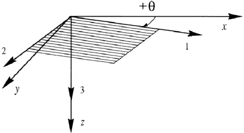
Figure 27: Laminate coordinate system xyz, [33] ... 42
Figure 28: Layer and layer interface numbering convention for laminates, [33] ... 42
Figure 29: Rotation of layer axes notation, [33] ... 43
Figure 30: The Proton Motor 8 kW Fuel Cell stack, [35] ... 53
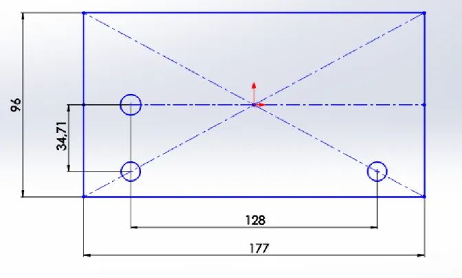
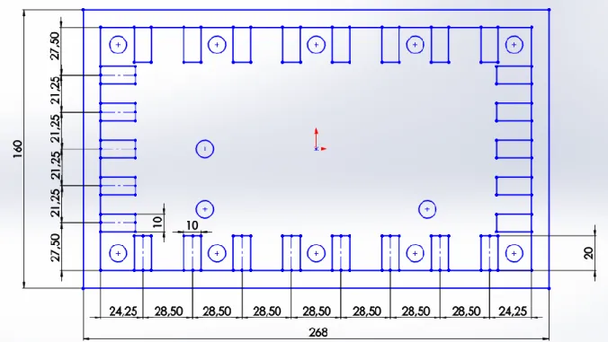
Figure 32: Assumed general dimensions for the graphite block and hole positioning... 56
Figure 33: FC metal EP stack Solid Works rendering ... 57
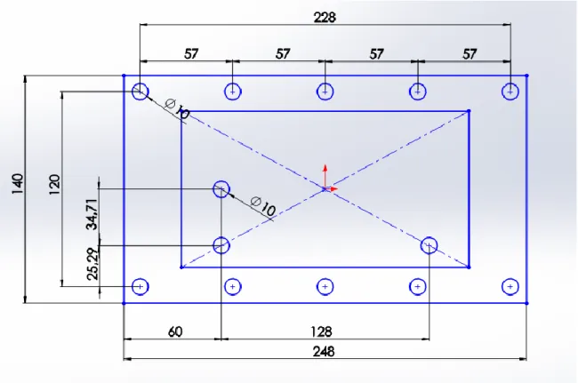
Figure 35: Normal plate dimensions. Positioning of holes and contact surface with graphite
block (inside rectangle) ... 59
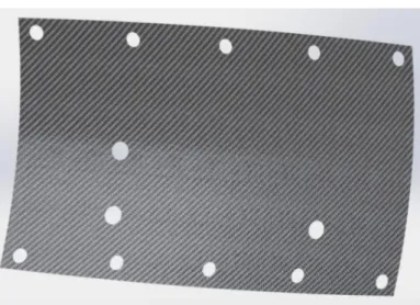
Figure 36: Normal plate with Solid Works rendering... 59
Figure 37: Pre-curvature plate curvature in the y-z plane ... 60
Figure 38: Pre-curvature plate curvature in the x-z plane ... 60
Figure 39: Pre-curvature plate sketched as surface ... 61
Figure 40: Conventional Shoe Box cover ... 61
Figure 41: Shoe Box concept with Solid Works rendering ... 62
Figure 42: Placement of supports in shoe box face ... 62
Figure 43: Dimensions of the support and epoxy adhesive ... 63
Figure 44: General dimensions of the Inertia plate ... 63
Figure 45: Front view of Inertia plate ... 64
Figure 46: Back view of the Inertia plate ... 64
Figure 47: Reinforcement plate general dimensions ... 64
Figure 48: Reinforcement plate Solid Works render ... 64
Figure 49: The UAV Engines Limited AR741 Wankel engine, [36] ... 67
Figure 50: Finite Element Geometry and Mesh of an applied concept ... 70
Figure 51: Representation of the model with applied loads (yellow arrows) and boundary conditions (blue and orange triangles) ... 71
Figure 52: Abaqus Composite Layup Manager ... 77
Figure 53: Example of tested assembly; Plate on the left, reinforcement in the middle, and graphite block to the right ... 79
Figure 54: Double pre-curvature plate; displacements disabled (orange triangles) in centre (U1,U2; x and y) and side (U2; y) ... 80
Figure 55: Loads (yellow arrows) and fixation (orange and blue triangles) seen from above 80 Figure 57: Top edge path on the graphite block ... 83
Figure 58: Bottom edge path on the graphite block ... 83
Figure 59: Displacement distribution in graphite block with pre-curvature end plate ... 84
Figure 60: Von Mises Stress distribution in graphite block with pre-curvature end plate ... 84
Figure 61: Placement of path for the graphite block, considering the pre-curvature plate ... 84
Figure 62: Displacement of each concept of the plate model with respect to the x-direction . 86 Figure 63: Deflection of each concept of the plate model with respect to the x-direction ... 88
Figure 64: Available energy of the considered FC systems with different EP materials, as well as ICE system ... 96
Figure 65: Specific energy of the considered FC systems with different EP materials, as well
as ICE system ... 96
Figure 66: Filament Winding concept assembly Solid Works rendering ... 102
Figure 67: General dimensions of the FW box... 103
Figure 68: FW tube fibre orientation ... 105
Figure 69: FW half stack assembly in Abaqus ... 105
Figure 72: Specific energy of the considered FC systems, as well as the FW concept and the ICE system ... 109
Figure 73: Dependency of the band gap, temperature and efficiency, [40] ... 126
Figure 74: Variation of output with insulation for representative sub-arrays, [39] ... 127
Figure 75: Epitaxial stacks of multi-junction solar cells, [39] ... 128
Figure 76: Force balance for an aircraft in steady level flight... 133
Figure 77: Schematic of an Alkaline fuel cell operation, [14] ... 136
Figure 78: Schematic of PAFC operation, [14] ... 138
Figure 79: Schematic of MCFC operation, [14] ... 139
Figure 80: Schematic of a SOFC operation, [14] ... 141
Figure 82: Schematic of the spray-up process, [30] ... 143
Figure 83: Schematic of the filament-winding process, [30] ... 144
Figure 84: Pultrusion, [30]... 144
Table of Tables
Table 1: Features of low and high temperature fuel, [12] ... 18 Table 3: Fuel Cell Reactions and the Corresponding Nernst Equations, [19] ... 24 Table 4: Ideal Voltage as a function of Cell Temperature, [19] ... 24 Table 5: Summary results of the assessment for Type III (T3) and Type IV (T4) single and dual-tank compressed hydrogen storage systems, [20] ... 31 Table 6: Compliance matrixes of isotropic (left) and transversely isotropic (right) materials. 41 Table 7: Categorization for UAS, UVS International ... 46 Table 9: Proton Motor 8 kW features, [35] ... 53 Table 10: Metal End Plate mass and mass ratio to FC stack total mass for aluminium and steel ... 56 Table 11: Composite ply thickness, stacking sequence and resulting plate thickness ... 57 Table 12: Flexural Stiffness (EI), curvatures (R) of the best performer composite plate tested in [18] ... 60 Table 13: Conceptual plates ... 65 Table 14: Technical specifications of the selected engine - UAV Engine Limited AR741 Wankel engine, [36] ... 67 Table 15: Component Geometrical sketch procedure ... 72 Table 17: Mechanical Properties of the considered isotropic materials, and respective mass density ... 76 Table 18: Toray M40J Fibre Properties ... 76 Table 19: Mechanical Properties of the considered orthotropic material, and mass density ... 77 Table 20: Carbon/epoxy stacking sequence and ply thickness for the considered composite parts ... 77 Table 21: Contact description and representation ... 78 Table 22: Equivalent force per hole for the metal and composite end plates ... 81 Table 26: Stress and displacement distribution in the graphite block's face for every tested concept ... 89 Table 27: PM 8 kW, PM 4 kW and proposed combination masses ... 93 Table 28: Mass ratio of 2 end plates and determination of the mass of the remaining components ... 93 Table 29: Total mass for the steel and CFRP Plate 4 and 8 kW FC stack ... 93 Table 30: Total stack mass for aluminium, steel and CFRP ... 94 Table 32: Contained energy and specific energy for the aluminium, steel and CFRP FC stacks, according to the gravimetric targets of the DOE ... 95
Table 33: Contained energy and specific energy for the aluminium, steel and CFRP FC stacks,
according to the gravimetric targets of the DOE, considering 60% overall efficiency ... 95
Table 36: Contained energy and specific energy of the ICE propulsive system, considering 30% overall system efficiency ... 96
Table 37: Comparison Specific Energy ICE-CFRP FC ... 96
Table 38: Comparison Specific Energy CFRP FC-Al FC ... 96
Table 39: Part description for FW model... 103
Table 40: Material definition for the used parts in the FW model ... 104
Table 41: Carbon/epoxy stacking sequence and ply thickness ... 105
Table 42: Mass of the parts used in the FW model ... 106
Table 43: Determination of remaining mass for the FW 8 kW stack mass ... 107
Table 44: Determination of remaining mass for the fw 4 kW stack mass ... 107
Table 45: Equivalent mass for 2 EP and FC stack mass for the 8 kW and 4 kW considering the FW model ... 107
Table 47: Calculus of the available mass for fuel (H2) for the FC propulsive system in the FW model ... 108
Table 48: Contained energy and specific energy for the aluminium, steel and CFRP FC stacks, according to the gravimetric targets of the DOE for the FW model ... 108
Table 49: Contained energy and specific energy for the aluminium, steel and CFRP FC stacks, according to the gravimetric targets of the DOE, considering 60% overall efficiency for the FW model ... 108
Table 50: Efficiency of the different types of PV ... 129
Table 51: Specific strength of rotor materials, [29] ... 130
Table 52: SFC DMFC Development ... 137
Table 53: AMI Portable SOFC Development ... 140
Table 54: Manufacturing Process selection criteria, [30] ... 142
List of Acronyms
AFC Alkaline Fuel Cell
AUV Autonomous Underwater Vehicle
BoP Balance of Plant
CFRP Carbon Fibre Reinforced Polymer
CHP Combined Heat and Power
CVT Continuously Variable Transmission
DMFC Direct Methanol Fuel Cell
DOE Department of Energy
EM Electric Motor
EP End Plate
FC Fuel Cell
FW Filament Winding
GDL Gas Diffusion Layer
GFRP Glass Fibre Reinforced Polymer
ICE Internal Combustion Engine
IST Instituto Superior Técnico
LAETA Laboratório Associado para Energia, Transportes e Aeronáutica
MCFC Molten Carbonate Fuel Cell
MEA Membrane Electrode Assembly
MTOW Maximum Take-off Weight
NATO North Atlantic Treaty Organization
PAFC Phosphoric Acid Fuel Cell
PEM Proton Exchange Membrane
PM Proton Motor
PV Photovoltaic
RTM Resin Transfer Moulding
SOFC Solid Oxide Fuel Cell
UAV Unmanned Aerial Vehicle
UAS Unmanned Aerial System
UBI Universidade da Beira Interior
1. Introduction
1.1 INEGI
INEGI was originally formed by the Department of Mechanical Engineering of the Faculty of Engineering of the University of Porto (FEUP) in 1986 and it still holds that connection to the departments of Mechanical Engineering and of Industrial Engineering and Management that constitute its strongest links to scientific and technical knowledge and training and expertise. In its 26 year existence INEGI developed and consolidated a strong partnership with the Industry in Research, Development and Innovation (R&D+I) projects. Today INEGI’s R&D+I projects under contract with the Industry account for more than 60% of its turnover. As a private non-profit association and a public service entity (Entidade de Utilidade Pública) INEGI is positioned as an agent with responsibilities for the development of the Economy and Society contributing towards the development and consolidation of a competitive model based on knowledge and technological density in-and-of products, processes and technological based innovation. Currently the Institute has 62 Associated Institutions that represent all spheres of activity from the University of Porto to Industrial Associations in relevant fields of INEGI’s activity as well as Private Companies and Public Institutions. INEGI is governed by a board which is formed by three representatives from private industrial associates and two representatives from the University of Porto thereby ensuring its positioning as an institution oriented towards the economic and social valorisation of R&D results, knowledge and technology. The Board reports to the General Assembly of the Private and Public Associates.
INEGI’s organizational structure relies on around three pillars of activity in different technology readiness levels, maintaining a strong competence matrix element:
Research
Innovation and Technology Transfer (ITT) Consulting and Services
At its base, INEGI’s structure is formed by different scientifically and technologically specialized Units which support research activity, ITT and consulting. Most significantly ITT and Consulting are especially directed towards the development of solutions for private companies. This organizational structure is specialized in the development and innovation projects of high technological complexity that require the integration of multidisciplinary knowledge and competences.
INEGI is part of a Research Unit of the Associated Laboratory for Energy, Transportation and Aeronautics (LAETA), which also counts as members the Mechanical Engineering Institute – IST, the Mechanical Engineering Institute - FEUP, the Centre for Aerospace Sciences – IST,
the Industrial Aerodynamics Institute at the University of Coimbra and the Aeronautics and Astronautics Research Center of the University of Beira Interior.
INEGI owns a diverse set of facilities and equipment in order to support its activity, namely laboratories (some of which are accredited laboratories), experimental and development laboratories (capable of producing components and pre-series) and an extensive engineering software catalogue. Software available at INEGI ranges from CAD (including CATIA), FEM (including ABAQUS), CAM, casting simulation, sheet metal forming, as well as other tools that support INEGI’s work on Wind Energy consulting, such as WAsP and WindFarmer for atmospheric studies and GIS (ArcGis).
INEGI’s staff is composed of 170 people, 80% of whom are graduates or post-graduates. This number is complemented with c. 50 academic researchers from the Faculty of Engineering of the University of Porto.
1.2 The Electric Long Endurance UAV Project and the NATO
Unmanned Vehicle Study Group
This dissertation was carried out in the context of an internship that took place at INEGI, within the scope of the “Electric Long Endurance Unmanned Aerial Vehicle (ELE-UAV)” project jointly proposed by IST, UBI and INEGI teams of Laboratório Associado para a Energia, Transportes e Aeronáutica (LAETA) for the development of a small sized aircraft intended for civilian applications.
The multidisciplinary project aims to put together the special skills of each participating member in a broad range of fields of study concerning subjects such as Aerodynamics, Propulsion, Mechanical Project, Structures & Materials, Non-Destructive Inspection, Aerodynamic Project, Optimization, Avionics, Aerial Control and Transportation, among others. Those areas are expected to experience sustained development, so that a sharing network of research, skills, and knowledge can be created within the LAETA.
The sharing of knowledge and technical expertise is expected to enable scientific research, within its own specific time and budget limitations, as well as solving of actual practical problems that come up during its implementation.
Furthermore, INEGI is currently participating in a NATO study group for the implementation of fuel cell systems in Unmanned Vehicles (UVs), being that INEGI is solely focused on the Unmanned Aerial Vehicles (UAV) part. This dissertation also contributed to solving problems in the on-going work of that study group.
The initial objectives of this project were to provide with a State-of-the-Art gathering of electrical propulsive technologies for high endurance, followed by a proper analysis and comparison of each, as well as a practical assignment of physically collaboration in the multidisciplinary construction of the aforementioned aircraft.
1.3 Report Organization and Dissertation Objectives
1.3.1 Report Organization
Chapter 1 provides with an introduction to the work, along with the initial general objectives for the dissertation.
Chapter 2 states and compares possible propulsive systems that can be implemented in a UAV, starting with a modelling/comparison of the efficiencies of different Conversion Processes, with a special focus on fuel cell systems.
Chapter 3 provides a description of the path taken to conceptual development, explaining the motivation behind every concept that came up, along with the necessary assumptions made. Chapter 4 contains all of the necessary information regarding the construction of the numerical modelling, and the achieved results.
Chapter 5 includes a discussion of the numerical model results, and provides with the necessary calculations to specific energy of each system, so as to provide a comparison between them.
Lastly, an analysis and comment of the preceding chapters, along with the conclusions to the project are made in chapter 6. Furthermore, a suggestion of possible future studies and work, that are required if de facto implementation of the suggested concepts is eventually intended. Furthermore, a suggestion of an alternative approach to stack fixations is also included.
The final annexes of this report include the references of the consulted and cited sources, as well as attachments.
1.3.2 Dissertation Objectives
Unmanned aerial vehicles/systems are aircrafts without the presence of a human pilot. The aircraft is controlled either remotely by a pilot on the ground or autonomously through a computerized system. The absence of human presence, with its inherent flexibility (physiological limitations), allows this type of aircraft systems to perform missions ranging from dull to life threatening scenarios, in fact, they are commonly categorized as "dull, dirty and dangerous", [1]. Furthermore, the inexistence of life-support systems and the possibility of being built on a smaller scale lead to decreased construction and operational cost, as well as lower fuel consumption.
The working principle of a fuel cell was discovered back in the 19th Century; however they have only recently been the target of significant research and development, and interest of energy consuming devices manufacturers. Its working principle, although extremely complex, can be very basically explained as the inverse principle of the water electrolysis. Being a non-pollutant (depending on FC type and manner to which fuel is obtained), and noiseless power source makes them particularly attractive in some applications, and such is the case of unmanned aerial vehicles. This report will focus on polymer electrolyte membrane (PEM), also known as proton exchange membrane fuel cells. PEM FC have gathered significant attention due to advantages such as low-temperature operation, rapid start-up and high power density, which makes them particularly applicable to transportation systems, [2].
Composite fibre reinforced materials are nowadays widely used in a broad range of applications, in particular in the aeronautical and defence industries. Their high specific
strength and stiffness, along with the possibility of providing the required mechanical properties in the necessary directions, taking into account the predicted loads beforehand, poses as an edge over other more conventional materials, and has led to increased usage in the past years. Another important characteristic is their ability of improving chemical resistance according to the working environment, leading to high chemical attack strength.
This dissertation was first set out to be an analysis of the possible propulsive systems of an UAV. A state of the art gathering of the possible propulsion systems for an unmanned aerial vehicle was accomplished, with a special focus to fuel cell systems. Yet, the objective of the dissertation changed and focused itself on an important matter regarding fuel cell viability in UAVs.
This paper intends to demonstrate a way to introduce a fuel cell system in a UAV as a feasible and viable propulsion system. Not considering cost, the greatest limitation that a FC system faces in its introduction in aerial vehicles is perhaps its Specific Energy (Wh/kg). If significant and sufficient mass reduction were to be achieved, then its specific power and energy would be increased, along with an edge over other propulsive systems.
The End Plates, along with the necessary fixation components (screws, bolts, etc.), account for a considerable part (36%, according to [3]) in the total system weight. Commonly used materials for end plates are steel and aluminium . This paper proposes an overall system weight reduction through the replacement with Composite Materials, in particular Carbon Fibre Reinforced Polymer (CFRP) .
Another challenge that is intended to be resolved through this suggested material replacement is End Plate deformation. A High Modulus CFRP with high stiffness properties is expected to have smaller deflection in the End Plate, and consequently smaller deflection in the Bipolar Plate, even leading to possible lesser mass requirement in the Bipolar Plate and subsequent potential increase in fuel cell reliability. It has been shown that Plate deformation, and a consequent non-uniform pressure over the Bipolar Plates, leads to decreased system performance, [2],[4]. It is therefore possible to say that higher specific power and energy can be directly or indirectly achieved if the End Plate can provide lesser deflection. Several articles [5], [6], [7] suggest the introduction of lighter materials in the bipolar plates is bound to occur. If that turns out to be true in the future, than the End Plates, along with the required fixation components will also be expected to have a bigger part in the total system weight, making a mass reduction in the End Plate increasingly more interesting.
From the outcome combination of the stress-strain uniform state, along with decrease in overall system mass, the determination of the specific energy of the FC system prior and after the implemented changes will be performed. As means of comparison, the difference between the two will be the achieved gain in specific energy and contained available energy. Furthermore, that gain in specific energy will also be compared with a conventional internal combustion engine (ICE) system, in order to ascertain the viability of the fuel cell when compared with currently used systems.
2. Literature review
This section is an extended summary containing all the gathered information from several reliable sources throughout the work period, as well as the required skills and tools to the accomplishment of the proposed goal. It poses as an essential part to the dissertation, for not only it would not have been possible to have accomplished the proposed work, but also because it stands as a state-of-the-art gathering of several important matters regarding UAV propulsion, which can hopefully prove its usefulness in the future.
As stated before, the objectives for this dissertation have changed considerably throughout the work period. Study over very interesting and relevant fields of study to the UAV propulsive system, such as Photovoltaic Cells, Kinetic Energy Systems and Basic Aeronautics, was carried out, however they were not found suitable regarding this dissertation's ultimate objective. For that matter, they are not present in this section. However, they can be found as annexes in the hindmost pages of this report (see Annexe E).
2.1 Introduction to Conversion Processes
According to John H. Scott [8], there are fundamentally two means of modelling the conversion of chemical bond energy into electricity: the Carnot theory (based on heat engine conversion analogies) and electrochemistry (related to direct chemical-electrical conversion) see Figure 1.
Figure 1: Chemical-to-electric energy conversion. Heat engine conversion and direct conversion have fundamentally different ideal limits on thermodynamic efficiency, [8]
2.1.1 Heat Conversion
Heat conversion engines based on fluid cycles are currently the most commonly used [8]. Their working principle comprises four stages in which the working: is compressed, heated through chemical reaction, and expanded (whereby one obtains mechanical work), and finally cooled.
The formalization of a model for this idealized heat engine was proposed by Carnot in the Carnot cycle, see Figure 2. This model allows the understanding of how the laws of thermodynamics limit the idealized maximum efficiency of a heat engine through a relation between the temperature at which heat is added to the system, the "topping" temperature, , and the temperature at which waste heat is rejected from the system, the "bottoming" temperature, .
Figure 2: The Carnot cycle shown on a T-s diagram, [9]
The actual efficiencies with practical heat engines are, however, much lower than that of an ideal Carnot cycle operating between the same and . This is due to the fact that the construction of engines with isothermal processes at the topping and bottoming temperatures is impractical because it is impossible to build a thermodynamically reversible engine, i.e., a system without the production of entropy (dissipation of energy).
In order to overcome these difficulties, the following fluid cycle heat engines are commonly in use, with examples of operation in brackets:
The Diesel/Otto cycle (e.g., the automotive internal combustion); The Brayton cycle (e.g., jet engines and gas turbines);
The Rankine cycle (e.g., reciprocating steam engines and steam turbines); The Stirling cycle (e.g., currently used in small high-efficiency refrigerators).
The thermoelectrical and photovoltaic energy conversion systems, characterized by their relatively low efficiencies, can also see their efficiency modelled through the Carnot theory. The thermoelectric conversion based on the Seebeck effect, comprises the direct conversion of differences in temperature to electric voltage and vice-versa and without the presence of any moving parts. The Electromotive Force (EMF) of a thermocouple is defined by the theory of thermoelectricity as the difference in the absolute thermoelectric power, , between two metals or alloys that constitute the thermocouple. The temperature gradient throughout the two arms, consisting of two metals, A and B, of the thermocouple results in the generation of voltage, , and is calculated through the integration limits of temperature at junction 1, , and at junction 2, , as in Equation 2.1.
Equation 2.1
Where and are the thermoelectric power of metals A and B, respectively.
There is no general equation for absolute thermoelectric power of a metal. Since copper and lead have plenty and accurate experimental data, these two metals are reference materials in thermoelectricity. As seen in Figure 3, the thermoelectric power for both metals is negative at low temperatures, beneath . That of lead, however, remains negative over the whole temperature range.
Figure 3: Low-temperature absolute thermoelectric power for copper and lead, [10]
For practical industrial applications, however, alloys are used as thermocouples rather than pure metals. Figure 4 shows the absolute thermoelectric power for some alloys (chromel and alumel) and pure metals (platinum and copper) that are commonly used in thermocouples in different combinations and with other metals and alloys, being platinum the third reference material in thermoelectricity. Also, since thermoelectric power for platinum and alumel is negative, their curves are shown as .
Figure 4: High-temperature absolute thermoelectric power for copper, platinum, chromel and alumel, [10]
As for the photovoltaic conversion, it is a technology that has experienced a fast development and growing usage over the past few years and has proven to be a practical and viable method for conversion of the solar electromagnetic energy to electricity. Even though this type of conversion cannot be strictly considered a heat engine, its efficiency can be modelled using
the Carnot theory, which will not be addressed in this report. Further discussion over this technology is available in the annexes (see Annexe E).
2.1.2 Direct Conversion
Direct conversion systems are based on the direct conversion of chemical energy to electrical energy. These energy conversion systems cannot see their efficiency modelled through the Carnot theory, since they do not comprise the step of heat release previously seen for Heat conversion engines.
As seen from Figure 1, these systems are categorized into batteries and fuel cells. The principle of operation of batteries, the most common and widely used direct conversion system, is based upon the oxidation/reduction reactions that take place within the device which leads to the degradation of the electrodes. They can be further divided into primary and secondary. In the first, the electrodes are consumed irreversibly, making them discarded after use. In the latter, however, the electrode materials are regenerated during recharging. It is possible to make infinite combinations of fuel and oxidants as electrode material for battery. The total available energy for both kinds of batteries is, therefore, proportional to the amount of electrode material contained in the device.
The electrodes in Fuel cell systems are, however, not consumed. Instead they provide the site in which the chemical reactions between fuel, oxidant and transported ions, driven by catalysers, will take place as long as the reacting chemicals, i.e., fuels and oxidants, are fed. The total energy available in a fuel cell system is related to the amount of reactant stored in such a system, a feature than can be compared to an Internal Combustion Engine (ICE).
2.2 Efficiencies of Conversion Processes
2.2.1 Heat Engines and the Carnot Cycle efficiency limitation
As previously mentioned, a heat engine is defined by the four requirements below. It should be noted that, although it is possible to model the efficiency of the Photovoltaic and Seebeck effects through the Carnot Theory, they are not considered heat engines.
1. Receives heat from a high-temperature source (e.g., coal furnace, nuclear reactor); 2. Converts part of this heat to work (e.g., by a turbine);
3. Rejects the remaining waste heat to a low-temperature sink (e.g., atmosphere, river); 4. Operates on a thermodynamic cycle.
Some heat engines do not follow the requirement of operating on a thermodynamic cycle. Such is the example of internal combustion engines and gas turbines, for instance, since the employed working fluid is continuously replaced, the resulting combustion gases are exhausted and the input of new volume of air takes place to prepare the following cycle. The steam power plant however follows perfectly the mentioned requirements, since it receives heat from an external combustion chamber, extracts work through a turbine and rejects the heat to a condenser.
Since for a cyclic process, the initial and final states are identical, the First Law relation involves only the heat input and work output terms, as in Equation 2.2.
Equation 2.2
Thusly, one can conclude that the net work performed by the system equals the net heat flow that enters it, see Equation 2.3.
Equation 2.3
Since at least two thermal reservoirs are involved in the cycle of a heat engine, with heat entering the system from the high-temperature reservoir and heat exiting the system to the low-temperature reservoir, one can define that the net work, , in Equation 2.4 is the difference between the heat input, , and heat output, , of the system.
Equation 2.4
The thermal efficiency, , of a heat engine is determined by the amount of work converted from the amount of energy input into the system, as in Equation 2.5.
Equation 2.5
Combining Equation 2.4 and Equation 2.5, one can reach the following conclusion regarding thermal efficiency, as in Equation 2.6.
Equation 2.6
The conclusion drawn from the previous equation is that the smaller the ratio between the heat output and the heat input, the higher the efficiency.
The Carnot cycle involves four reversible processes, as depicted in Figure 5 with a piston in a cylinder. The idealized cycle of Carnot deemed all the processes to be conducted in a
reversible manner, since that would be the way to achieve the maximum possible work in a heat engine.
The four stages of the reversible Carnot cycle: (1-2): isothermal expansion
(2-3): adiabatic expansion (3-4): isothermal compression (4-1): adiabatic compression
Figure 5: The four stages of the reversible Carnot cycle, [9]
Since heat addition and heat rejection are performed reversibly and isothermally, and considering Equation 2.7, Equation 2.8 can be used to determine the efficiency of the cycle.
Equation 2.7
Equation 2.8
Equation 2.9 is the heat addition step (1-2), and Equation 2.10 is the heat rejection step (3-4).
Equation 2.9
Equation 2.10
One observes from Figure 2 that during the reversible adiabatic processes, steps (2-3) and (4-1), the entropy remains the same. The shaded area in the figure representing the net work, , is shown to be the difference between the heat input, , and the heat output,
.
Since the entropy terms in Equation 2.9 and Equation 2.10 are identical, i.e.:
Equation 2.11
Equation 2.12 is the result of the substitution of Equation 2.11 into Equation 2.6, the thermal efficiency of the Carnot cycle and the maximum possible conversion efficiency for any heat engine, since all of the processes are reversible.
Equation 2.12
It is then determined that the maximum thermal efficiency of a thermodynamically reversible heat engine depends upon the ratio of low and high temperatures in the thermodynamic cycle. Since the low temperature is usually fixed (ambient temperature), the efficiency is determined by the highest temperature in the cycle: the higher the temperature, the higher the efficiency.
2.2.2 Conversion efficiency of Direct Conversion systems
The efficiency of a Fuel cell can be determined according to two definitions. The first, based on the First Law of Thermodynamics, can be used as ground of comparison with thermal heat engines. Like in the previously demonstrated Carnot efficiency, it compares the work produced by the cell with the fuel's heating value.
The second, based on the Second Law of Thermodynamics, compares the cell's actual performance with the maximum work it could develop. To make an analogy with Heat engines, it would be as comparing the actual work of the engine with its Carnot efficiency. First Law Efficiency
In an electrochemical cell, the system operates at constant temperature (isothermal process), i.e., the products of the reaction leave at the same temperature as the reactants, assuring that more of the chemical energy of the reactants is converted to electrical energy, instead of being consumed to raise the temperature of the products. Since the process is isothermal, the Carnot efficiency cannot be applied. Instead, the maximum work for an electrochemical cell, , is equal to the change in the Gibbs function (or Gibbs energy), , between products and reactants (see Equation 2.13).
Equation 2.13
In this case, the work is performed by the movement of electrons through a difference in electrical potential, , and is related to the charge, , of the electrons moving through a potential difference, , resulting in Equation 2.14.
Equation 2.14
In the previous equation, is the number of electrons transferred per mole of fuel and F is the charge carried by a mole of electrons, which is Faraday's number ( ). The First Law efficiency, i.e., the maximum thermal efficiency of an electrochemical cell is, as in heat engines, a ratio relating the net work of the system, yet the heat input, , is substituted for the higher heating value (HHV), resulting in Equation 2.15.
Equation 2.15
It is in the equilibrium condition in which no current is being drawn from the cell, the open circuit voltage, , that the maximum thermal efficiency of an electrochemical cell is obtained. For a hydrogen-oxygen fuel cell, the value of the open-circuit voltage, at and , equals (this value can be determined by relating Equation 2.13 and Equation 2.14 and by using the tabulated Gibbs energy data). Substituting the value of results in the maximum thermal efficiency for the previously mentioned conditions (see Equation 2.16).
Equation 2.16
Taking into account an ambient temperature of , the value of the high temperature in the Carnot cycle would have to be to match the 83% efficiency of Equation 2.16, as demonstrated in Equation 2.17:
Equation 2.17
The reversible work for an electrochemical cell that uses hydrogen and oxygen is compared to the reversible work of a heat engine in Figure 6. The change in the Gibbs energy of the reaction decreases with the rise of temperature. Analysing Equation 2.13, one is able to see that that situation will result in a decrease in the maximum work output of the fuel cell with the rise of temperature.
Figure 6: The reversible work produced by a H2/O2 fuel cell is greater than that of a Carnot engine at temperatures below 950 K. At higher temperatures, the Carnot engine is able to convert more of the
HHV of H2 (285,840 kJ/mol) into work, [9]
The Gibbs energy of the formation of water vapour is at the previously mentioned conditions and and decreases to at . As seen from Figure 6, the reversible work of the heat engine, using the HHV of hydrogen as the source of heat, increases with temperature. That is due to the fact that the Carnot cycle efficiency increases as well. The minimum temperature for which more reversible work is drawn from the combustion of hydrogen in a heat engine, rather than by direct conversion via fuel cell is, as seen in Figure 6, ).
Thermal efficiency of car engines is usually calculated in terms of power, meaning the heat input written as a rate according to the flow rate of fuel. An attempt to do the same in the calculation of the efficiency of a fuel cell, leads to the appearance in the equation of a factor related to the completeness of the combustion of fuel consumed to produce an electrical current. The analogous concept to completeness of combustion in direct conversion systems is fuel utilization, a measure of the fuel consumed to produce an electrical current, leading to the equation of the electrical efficiency, detailed in Equation 2.18.
Equation 2.18
In Equation 2.18, is the current in Amperes and is the flow rate of fuel in mol/sec. As seen from the previously mentioned equation, the inverse of the electrical efficiency is the
fuel stoichiometry. The fuel stoichiometry is in fact the relation between the amount of fuel fed and the amount required by the cell to provide the demanded electrons.
If hydrogen is in fact used as fuel, resulting in a current efficiency of 83% and considering that one mole of hydrogen contains two moles of electrons , that means that 83% of the hydrogen is converted to electricity, while the remaining 17% either leave the cell without reacting or having reacted non-electrochemically, i.e., not contributing its electrons to the cell current).
Second Law Efficiency
"The Second Law efficiency, , of an energy conversion device indicates its degree of reversibility, comparing the actual work against the maximum work potential", [9] (see Equation 2.19). The performance of an actual heat engine, for instance, would be the actual work performed by the engine divided by the work produced by a Carnot cycle engine. In a way, it is like comparing the actual work of an engine with the maximum it could provide.
Equation 2.19
Considering that, in a fuel cell, the thermal efficiency becomes voltage efficiency, as in Equation 2.20. Equation 2.20
The latter equation shows voltage efficiency to be a comparison between the actual voltage, , with the maximum possible voltage, . The actual meaning of this inefficiency applied to a Fuel cell represent is its losses (polarization) due to irreversibility. These phenomena will be further discussed in Section 2.3.4.
2.3 Fuel Cell
The basic principle of operation of a fuel cell consists in reversing water electrolysis to generate energy (electricity and heat) and water from hydrogen and oxygen. It was first discovered in 1839 by William Grove and remains unchanged until today.
"A fuel cell is an electrochemical "device" that continuously converts chemical energy into electric energy (and some heat) for as long as fuel and oxidant are supplied.", [9]
Like mentioned previously, fuel cells, unlike batteries, continuously generate electricity, as long as fuel is supplied. The fuel, like previously demonstrated, does not go through any type of combustion, resulting in a quiet process, pollution free (again, depending on FC type and manner to which fuel is obtained) and increased efficiency when compared with combustion processes.
The theoretical specific energy of hydrogen and oxygen combined in an electrochemical reaction is [11]. However, when the mass of fuel and oxidant storage tanks, as well as the mass of the fuel cell itself is taken into account, the overall specific energy density is reduced to values no greater than - still several times higher than that of a battery.
According to the Manwearable Study Group Report [12], there are three main markets for fuel cell technology: stationary power, transportation power and portable power.
2.3.1 Types of fuel cells
The primary classification of a fuel cell is related to the kind of electrolyte used. That classification leads to the knowledge of the kind of chemical reactions that take place in the cell and other factors, such as, [13]:
the kind of catalysts required;
the temperature range in which the cell operates; the fuel required;
other.
2.3.1.1 Reactant type
Fuel
As the reducing agent, fuel cells are able to use hydrogen, methanol, methane, carbon monoxide , and other organic substances, as well as some inorganic reducing agents (e.g., hydrogen sulphide, hydrazine)
Oxidizing agent
As the oxidizing agent, fuel cells can use pure oxygen, air oxygen, hydrogen peroxide and chlorine. Versions with other exotic reactants have also been proposed, [12].
2.3.1.2 Electrolyte type
Fuel cells can use liquid electrolytes and solid electrolytes. Within the liquid electrolytes one can distinguish aqueous solutions of acids, alkalis and salts, and molten salts. The most common solid electrolytes are ionically conducting organic polymers, and inorganic oxide compounds.
Besides serving as separators, i.e., keeping reactants from reaching the wrong electrode space, solid electrolytes also have the advantage of reducing the danger of leakage of liquids from the cell. A liquid leakage in a fuel cell device may be a serious problem, since it may lead to corrosive interaction with the construction materials.
2.3.1.3 Working temperature
One distinguishes low-temperature fuel cells, those having a working temperature of no more than ; and high-temperature fuel cells, over . Low-temperature fuel cells include membrane-type fuel cells, alkaline fuel cells and phosphoric acid electrolyte. High-temperature fuel cells include fuel cells with molten carbonate (working High-temperature to ) and solid-oxide fuel cells (working temperature above ). In recent years, interim-temperature fuel cells with a working temperature in the range to have been introduced. These include certain varieties of solid-oxide fuel cells developed more recently. The temperature ranges are stated conditionally.
The following table compares the different features between low temperature and high temperature fuel cells:
Table 1: Features of low and high temperature fuel, [12]
Low temperature FC High temperature FC
Generally incorporate precious metal
electrocatalysis to improve performance
Increased operating temperature reduces the need for expensive electrocatalysts
Require a relatively pure supply of hydrogen as a fuel (e.g. PEM catalysts are poisoned by carbon monoxide; AFCs damaged by carbon dioxide). This usually means that a fuel processor is required to convert primary fuels such as natural gas
Fuel flexibility: can be operated on a range of
hydrocarbon fuels;
Benefits in Combined Heat and Power (CHP) generation
Exhibit fast dynamic response and short start-up times
Exhibit long start-up times and are sensitive to thermal transients
Available commercially May require expensive and exotic construction
materials to withstand the operating temperature, particularly in the balance of plant (piping, heat exchangers, etc.)
Reliability and durability may be a concern
2.3.2 Overall Comparison
Below is compiled a table resuming the main features of the different types of fuel cells previously discussed.
Table 2: Fuel cell Type Comparison, [14] Fuel cell Type Common
Electrolyte Operating Temperature Typical Stack Size
Efficiency Applications Advantages Disadvantages
Alkaline (AFC) Aqueous solution of potassium hydroxide soaked in a matrix 10-100 kW 60% Military Space Cathode reaction faster in alkaline electrolyte, leads to high performance Low cost components Sensitive to CO2 in fuel and air Electrolyte management Polymer Electrolyte Membrane (PEM) Perfluoro sulfonic acid , Typically < 1 kW-100 kW 60% transportation Backup power Portable power Distributed generation Transportation Specialty vehicles Solid electrolyte reduces corrosion & electrolyte management problems Low temperature Quick Start-up Expensive catalysts Sensitive to fuel impurities Low temperature waste heat Phosphoric Acid (PAFC) Phosphoric acid soaked in a matrix 400kW 100 kW module 40% Distributed generation Higher temperature enables CHP Increased tolerance to fuel impurities Pt catalyst Long start up time Low current and power Molten Carbonate (MCFC) Solution of lithium, sodium, and/or potassium carbonates, soaked in a matrix 45-50% Electric utility Distributed generation High efficiency Fuel flexibility Can use a variety of catalysts Suitable for CHP High temperature corrosion and breakdown of cell components Long start up time Low power density Solid Oxide (SOFC) Ytrria stabilized zirconia 1kW-2MW 60% Auxiliary power Electric utility Distributed generation High efficiency Fuel flexibility Can use a variety of catalysts Solid electrolyte Suitable for CHP & CHHP Hybrid/GR cycle High temperature corrosion and breakdown of cell components High temperature operation requires long start up time and limits
Direct Methanol (DMFC)
Nafion <40% Portable electronic systems of low power, running for long times Technical maturity High energy density Fast start-up Commercially available Easy to carry and handle Simple to use
Toxic fuel Higher MEA cost (may limit cost reduction facing other technologies) Limited power density Exhaust moisture
2.3.3 PEM Fuel Cell
This work performed in this dissertation focused solely on PEM type FC, for that matter, there will be a detailed description of this particular FC system, while leaving the remaining studied types available as annexes (see Annexe E).
Firstly developed by General Electric in the 1960s for use in space exploration by NASA, the PEMFC, also called solid polymer fuel cell (SPFC), has known commercialization over the past few years and is currently the focus of several engineering studies, especially for applications in the automobile industry.
The low working temperature of the polymer electrolyte makes it easy for the PEMFC to start quickly. The fact that the system does not contain any corrosive fluid combined with the ability of working in any orientation makes it particularly suitable for portable applications, such as vehicles.
A disadvantage shared with the Alkaline FC (see Annexe E) is that liquid water also forms at the cathode at the operating temperatures. Again, the humidity of the reactant gases must be controlled in order to avoid dry-out or flooding of the cell. While neither of which leads to cell destruction, either of which may lead to efficiency decrease and shortened operating life. Below are some advantages and disadvantages regarding PEM FC systems.
Advantages:
Highest power density within the range of fuel cells;
Simplest fuel cell in the range;
Has the potential to be used for vehicle applications;
Low temperature signature is
dependent upon the ability to manage the heat output;
Can work in reversible mode.
Disadvantages:
Pure Hydrogen as fuel;
Cost of fuel cell;
Water management difficult;
Need for expensive catalysts.
Reactions
Figure 7: Schematic of a PEMFC operation, [14]
Anode:
PEM Fuel Cell System Description
This sub-section provides a brief insight on the composition of a PEM FC system. As seen in Figure 8, a PEMFC comprises the following components:
Bipolar plates: conventionally graphite plates with machined gas flow-field channels. They provide a separation between the individual fuel cells and conduct current from cell to cell. The selected bulk material should have low electrical resistance, as well as low interfacial contact resistance between the GDL's and the bipolar plates, in order to improve fuel cell performance.
End Plates: The two outermost components placed on the extremities of the fuel cell stack. They are usually made of stainless steel or aluminium and are a part of the clamping system. Its major role is to provide a uniform pressure distribution between various components of the fuel cell stack and consequently reducing contact resistance between them, thus unitizing them.
Membrane electrode assemblies (MEAs): comprises the ion conducting electrode, a cathode and an anode, the primary components of the Fuel Cell, often referred to as the MEA, or simply a single-cell fuel cell. The most commonly used electrolyte in PEMFC is Nafion, [15]
Gas diffusion layers (GDLs): transports gases and ions to and from the rest of the MEA.
Gaskets: have a critical function, within the operation of a fuel cell, guaranteeing the sealing of the stack, while subjected to acidic liquid solution, humid air and hydrogen, as well as considerable mechanical stress. The durability of a fuel cell system is therefore greatly dependent on the durability and stability of gasket material, [16]
Figure 8: Schematic diagram of a PEMFC stack, [17]
The overall efficiency of the fuel cell depends on the performance of the bipolar/end plates in the fuel cell stack.
Figure 9: Relative weight components of a PEMFC using graphite bipolar plate, [3]
End Plates
As previously mentioned, the End Plates' main goal is to provide a compressive clamping force to the remaining stack components, in order to ensure good electrical contact (low Ohmic resistance) between the multiple layers within the stack. Adequate pressure is fundamental, for there are risks associated with too low and too high pressure. Low pressure will result in voltage drop, due to high contact resistance between gas diffusion backing and the bipolar plates, as well as possible leakage, both resulting in diminished system performance. Excessive or uneven pressure, however, will result in non-uniform current density and heat generation distribution which may cause hot spot formation in the MEA and finally its failure, as well as a change in the porosity ratio of the GDL, damaging it, and possible fracture of the bipolar plates, [2]
Figure 10 depicts the deflection of the end plates caused by the clamping force.
Figure 10: Deflection of End Plates of a Fuel Cell by clamping force, [18]
55%
19%
3,60%
2,60%
3,50%
17%
Bipolar Plates End Plates Current Collectors MEA & Gasket O-ring plate & connectors Bolts, nuts and washersTo clarify, main implications related with current End Plate use are, [4]:
Deformation of end plates has an influence on fuel cell performance and is difficult to control;
End Plates are typically bulky and heavy, as compared to the fuel cell stacks;
Tie rods tend to loosen up during service. This may cause leakage, bad electrical contacts and deteriorated performance of the fuel cell stacks;
Repeatability in pressure distribution can hardly be realized among the fuel cell stacks. "The optimum pressure value is achieved throughout the fuel cell active area, but in reality it can only be achieved in a very small portion of the area because of the structure in the conventional end plates. Therefore, the most relevant shortcoming of the existing end plate design is the difficulty of achieving a uniform pressure distribution over the fuel cell active area.", [4]
There has been much research on how to improve fuel cell performance, however very little of it has been focused on the end plates, and the pressure distribution between the fuel cell stacks, [18]
Figure 11: Effect of clamping pressure on the fuel cell performance, [2]
2.3.4 Ideal Performance and available energy measurement of a fuel cell
An important issue when dealing with this kind of energy storage technology is the need to have a general understanding of the effect of the stored reactant's conditions (pressure and temperature) on the electrical energy production. Such a relation is made through the Nernst equation.
The Nernst equation relates the ideal standard potential, , at for the cell reaction with the ideal equilibrium potential, , at other temperatures and partial pressures of reactants and products. In fact, the value of represents the theoretical limit of cell voltage and thus the highest efficiency that laws of thermodynamics will allow for a fuel cell with a given reactant pressure and temperature.
Table 3: Fuel Cell Reactions and the Corresponding Nernst Equations, [19]
Fuel Cell Cell Reactions Nernst Equation
Proton Exchange Membrane and Phosphoric Acid Alkaline Molten Carbonate Solid Oxide
(a) - anode P - gas pressure
(c) - cathode R - universal gas constant
E - equilibrium potential F - Faraday's constant
T - temperature (absolute)
As seen from Table 3, the higher the pressure of the fuel, the higher will the cell potential at a given temperature be.
The impact of temperature on the ideal voltage, E, for the oxidation of hydrogen is shown in Table 4.
Table 4: Ideal Voltage as a function of Cell Temperature, [19]
Temperature
Cell Type PEMFC AFC PAFC MCFC ITSOFC SOFC
Ideal Voltage (V)
1,17 1,14 1,03 0,91
There are however irreversible losses that decrease the ideal cell voltage and must be accounted for. The losses, which are often called polarization, overpotential, or overvoltage, originate primarily from three sources:
1. activation polarization 2. ohmic polarization
The actual voltage of the cell, , is then the ideal potential subtracted by the mentioned losses, as in Equation 2.21.
Equation 2.21
Figure 12: Ideal and Actual Fuel Cell Voltage/Current characteristic, [19]
As seen in Figure 12, the activation polarization occurs at low current density. Its physical significance is similar to that of the static friction and represents the limiting effects of the oxidation/reduction kinetics. In a way, they are the electronic barriers that have to be overcome prior to current and ion flow takes place.
Ohmic polarization increases linearly with the increase in current, since cell resistance is essentially constant.
Concentration losses come as the result of starvation at certain reaction sites, as a consequence of fluid flow resistance. This type of losses takes place over the entire range of current density, however it becomes more prominent at high limiting currents when there is a inability of the surrounding material to maintain the initial condition of the bulk fluid.
1. activation polarization
Equation 2.22
Where is the electron transfer coefficient of the reaction at the electrode being addressed, and is the exchange current density.
2. ohmic polarization
Equation 2.23
Where is the current flowing through the cell, and is the total cell resistance, which includes electronic, ionic, and contact resistance.
![Figure 1: Chemical-to-electric energy conversion. Heat engine conversion and direct conversion have fundamentally different ideal limits on thermodynamic efficiency, [8]](https://thumb-eu.123doks.com/thumbv2/123dok_br/15213106.1019591/30.892.150.695.277.621/chemical-conversion-conversion-conversion-fundamentally-different-thermodynamic-efficiency.webp)
![Figure 3: Low-temperature absolute thermoelectric power for copper and lead, [10]](https://thumb-eu.123doks.com/thumbv2/123dok_br/15213106.1019591/32.892.225.634.119.528/figure-low-temperature-absolute-thermoelectric-power-copper-lead.webp)
![Figure 9: Relative weight components of a PEMFC using graphite bipolar plate, [3]](https://thumb-eu.123doks.com/thumbv2/123dok_br/15213106.1019591/44.892.188.660.112.390/figure-relative-weight-components-pemfc-using-graphite-bipolar.webp)
![Figure 11: Effect of clamping pressure on the fuel cell performance, [2]](https://thumb-eu.123doks.com/thumbv2/123dok_br/15213106.1019591/45.892.242.696.490.740/figure-effect-clamping-pressure-fuel-cell-performance.webp)
![Figure 16: Comparative analysis of the performance factor of various tank types, [24]](https://thumb-eu.123doks.com/thumbv2/123dok_br/15213106.1019591/52.892.138.720.799.1109/figure-comparative-analysis-performance-factor-various-tank-types.webp)