Stowage Planning of Large Containership with
Tradeoff between Crane Workload Balance and
Ship Stability
Liu Fan, Malcolm Yoke Hean Low, Huang Shell Ying, Hsu Wen Jing, Zeng Min, Win Cho Aye
Abstract— This paper describes an effective algorithm for generating basic stowage plans of large containership calling at a given number of ports. The algorithm applies an efficient block-based container allocation heuristic method of our previous work and taking into considerations more constraints in the real-world operations of commercial shipping line. The algorithm divides the cargo-space of a large containership into blocks, and assigns groups of containers to different partitions of the ship according to a set of heuristic rules. We present a practical test case and analyze the stowage plan generated by our system based on critical measurements such as the number of re-handles, crane intensity and ship stability.
Keywords— automation, container stowage, heuristics, tradeoff
I. INTRODUCTION
The stowage planning of a containership is one of the complex problems faced daily by all shipping lines. The problem is also known as the Master Bay Plan Problem (MBPP, Ambrosino and Sciomachen, 2004) [2]. It is a difficult problem because of its combinatorial nature and the various operating constraints related to both the ship structure and container properties. Existing stowage planning process is mainly carried out by human planners. These planners have not only years’ of training onboard containerships but are also familiar with the stowage instructions of container terminals.
A good plan can maximize the utilization of stowage space on a containership. This allows the containership to carry more commodities on board with fewer redundant moves of containers. It will also maximize the utilization of the quay cranes by making the stowage configuration possible for all cranes to operate simultaneously, ensuring a shorter berthing time for containership. However, a good stowage plan is not easy to generate, because it depends very much on the human planner’s experience and intuition about the shipping demands and characteristics of subsequent ports in the voyage. Thus the efficiency of ports and the utilization of ship space, and hence the operating cost of a shipping line, are highly dependent on the human planners’ performance.
Nowadays, millions of containers are transported by large
Manuscript received January 12, 2010. This work was supported by the Maritime and Port Authority of Singapore and APL.
deep-sea containerships all over the world daily. In order to satisfy the growing shipping demands and also achieve higher operation profits, the size of containerships has increased dramatically. The size of containerships has grown from relatively small 350 TEUs (Twenty-foot Equivalent Unit) to ten thousand TEUs. Shipping companies are facing increasing challenge in generating feasible and economic stowage plans for their containerships.
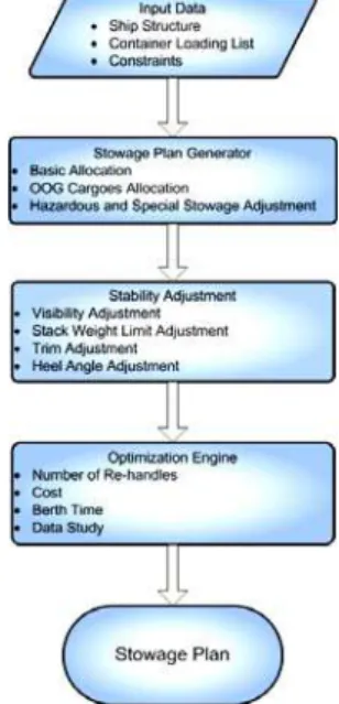
In order to cope with the challenge of maritime industry, the subject of our research is to develop a fully automatic stowage plan generation system for large deep-sea containerships. Figure 1 shows the architecture of the system.
Figure 1. System of automated stowage planning
The input data of the system consists of a ship profile that describes the structure of the containership and the operational constraints required by the maritime company, a list of containers which will be loaded at each subsequent port on a multi-port voyage and the stowage configuration of the containership at the first port of the voyage when the ship starts its journey.
First, the Stowage Plan Generator module generates a feasible stowage plan that satisfies a set of constraints. Note that as the stability of the ship is not considered in this module, certain constraints related to ship stability issue may be violated in the stowage plan generated by this module. However, the Stowage Plan Generator will still consider the weight distribution of containers. It applies different strategies to distribute the weight of containers Liu Fan, Malcolm Yoke Hean Low, Huang Shell Ying, Hsu Wen Jing,
throughout the ship.
Next, the stability adjustment module examines the ship stability indicators such as the line of visibility, stack weight limit, trim and heel angle of the feasible stowage plan and adjusts them to satisfy the stability requirements.
Finally, the optimization engine takes the feasible stowage plan, adjusted by the stability adjustment module, and optimizes it based on specific objectives such as minimizing the number of re-handles, maximizing the utilization of cranes, minimizing the berthing time or minimizing the operation cost.
In this paper, we focus on the work carried out in the stowage plan generator module. The work with reference to the other parts of the system is still in progress and will be discussed in our future papers.
The remainder of the paper is organized as follows. Section 2 reviews some related literatures in the domain of stowage planning. In section 3, we present some definitions and constraints of stowage planning problem. Our proposed heuristic method for stowage planning is described in Section 4. In Section 5, we present a case study and show some experimental results. Finally, Section 6 concludes the paper and outlines some future work.
II. LITERATUREREVIEW
Since the 1970s, the problem related to container stowage planning has been studied by shipping lines and researchers. The stowage planning problem is mainly referred to as the container loading problem, which is to decide the stowage configuration of a containership.
Initially the researchers mainly focused on establishing a set of 0-1 linear programming formulations which can express the stowage planning problem including all the constraints in a mathematical model. Theoretically if the linear programming formations are well defined, an optimal solution can be obtained. However, the search space of the established mathematical model depends on the ship capacity, the number of containers being considered and the operational constraints imposed by the shipping company and container terminal at each port. Even for a medium size containership, e.g. a 2000 TEUs vessel, the problem becomes a non-trivial one due to the large number of variables and inequalities needed for the formulations.
The stowage planning problem has been proven to be NP-complete and is related to the circle graphs coloring problem (Avriel et al., 1998, 2000) [7] [8]. It is very hard or even impossible to guarantee an optimal solution in a reasonable processing time for a real commercial sized containership. Thus, researchers have been trying to develop heuristic algorithms to provide workable solutions. A brief review of recent research follows.
The early study about the container loading problem can be traced back to the work by Aslidis in 1989[4] and 1990[5]. The author mainly focused on the problem related to the stacks. He developed an algorithm to calculate re-handles and a set of heuristic algorithms to minimizing them. However, his work only considered some special and small size case, and also ignored the stability problem which is a very critical issue in the stowage planning problem.
Avriel and Penn (1993) [6] developed a set of 0-1 binary linear programming formulations to model the stowage
planning problem. Through this model an optimal solution can be obtained. However, they found that this general algorithm is too slow even after they did some pre-processing of the data to reduce the number of variables and inequalities used in the formulations. Consequently, they tried to develop a Suspensory heuristic procedure to solve this problem with the aim of reducing the number of re-handles. This heuristic procedure provided very impressive performance in term of computation time. However, the algorithm did not take stability issue into account. All the containers considered are of the same size, and no special containers (e.g. reefers, high cubes) are considered. These assumptions make the Suspensory heuristic algorithm not flexible and thus cannot be used to solve the real-world stowage planning problem.
The first reported attempt to derive some rules for determining good container stowage plans is made by Ambrosino and Sciomachen (1998) [1], where a constraint satisfaction approach is used to define and characterize the searching space of feasible solutions.
In their follow-up work (Ambrosino and Sciomachen, 2004) [2], they described a 0-1 linear programming model for MBPP. They presented a heuristic approach before performing a 0-1 linear programming, which consists of a set of heuristic preprocessing and pre-stowing procedures that allow the relaxation of some constraints of the exact model to reduce the searching space of the model. Based on the pervious works they proposed a three phase algorithm for MBPP, which splits the ship into different portions and associate grouped containers with different subsets of bays without specifying their actual positions. Subsequently, they assign the actual position to each container by solving a 0-1 linear programming model. In the last phase, some local search exchanges are performed to check and remove possible infeasible solutions due to the cross and horizontal stability issues. However they assumed that the ship starts its journey empty at a port and visits a given number of other ports where only unloading operations are allowed. This means that the loading problem is only considered at the first port. This assumption is also un-realistic. Also, as a 0-1 linear programming approach is used in this algorithm, the computation time is still high, about 20 minutes for one plan, for large containerships.
homogenous weight. Because of this simplification, it is easy to make a balanced weight distribution. Also, the longitudinal balance issue was neglected in their study, and the algorithm requires 30 minutes to obtain a feasible stowage plan.
Xiao et. al. (2009) [15] proposed an effective algorithm to solve MBPP by introducing the concept of tolerance in the imbalance in workload from the perspective of quay cranes. By setting the tolerance to a suitable value, the algorithm can generate a stowage plan with less number of re-handle and efficient utilization of cranes, which are two important objectives of MBPP. They demonstrated their approach on a medium size containership and generated the stowage plan quickly within minute. While their experiments also did not consider issues on ship stability, their proposed framework did include a module on ship stability which is under development.
A recent research was carried out by Delgado and Jensen (2009) [9]. In this work, they applied Constraints Programming (CP) to stowage planning problem. They reported that the CP approach outperformed an integer programming and column generation approach in a preliminary study. However, they only tested their approach in a single under deck bay of a ship. This simplistic test lost the generality of the stowage planning, so cannot be applied to normal scenarios.
Since all the research mentioned above was carried out under simplistic assumption (except the work by Xiao et. al. (2009) [15], which is a work in progress), they can hardly be applied by companies operating shipping lines in real life, especially for large containerships. In this paper, we describe an effective stowage planning algorithm that is able to consider all the existing containership features and constraints to rapidly generate a set of feasible plans for a containership on a multi-port voyage.
III. PROBLEMDEFINITION
A. The Containership Structure
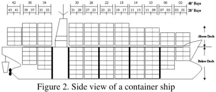
From the side view of the containership (see Figure 2), a containership contains a number of bays with bay number increasing from bow to stern. There are two kinds of bays, 40 foot (40’) and 20 foot (20’) bays, respectively. In particular, each 40’ bay is numbered with an even number, i.e. bay 02, 06, 10, etc. and each 20’ bay is numbered with an odd number. A 40’ bay is associated with two contiguous 20’ bays, e.g. bay 06 = bay 05 + bay 07.
Each bay consists of several rows, rows with an even number if they are located on the seaside, while an odd number if they are located on the quay side. Slots counted from bottom to top of a row form a stack.
Usually a bay is divided vertically by hatches into two sections, below deck and on deck. A bulkhead is an upright wall within the hull of a ship, which divides the under deck part of the ship physically into several cargo holds (the black thick lines in Figure 2 shows where bulkheads lie). Usually there are two bays between two bulkheads.
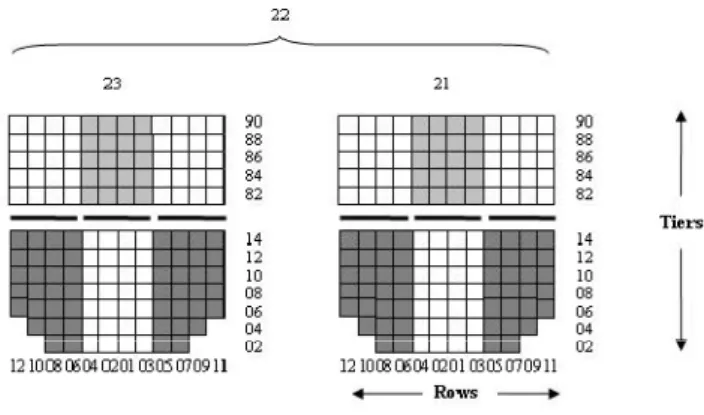
From the cross section view of a bay (see Figure 3), every bay contains a set of slots. Each slot is uniquely identified by three indices:
•bay, that gives the bay it is located in;
•row, that gives its position relative to the vertical section
of the corresponding bay (counted from the center to outside);
•tier, that gives its position relative to the horizontal section of the corresponding bay (counted from the bottom to the top).
Figure 2. Side view of a container ship
For example, a slot with id 040604 indicates that the slot is in bay 4, row 6 and tier 4. Our previous works (2009) presented a detailed explanation of how to use these three indices to identify a slot in the containership.
B. Types of Containers and the Related Constraints
In stowage planning, a container has many properties, such as its port of loading (POL), port of destination (POD), type, weight, etc. Together with the containership profile, the stowage plan generated which is subject to many constraints related to the ship structure, container characteristics and operational instructions. We list the main constraints of stowage planning in the following:
Standard containers. The dimension of a 40’ container is
equivalent to two 20’ containers. When a 40’ container is stowed into a 40’ slot (for instance, slot 180406), the corresponding two 20’ slots (slot 170406 and slot 190406) are also occupied and are not available for stowing 20’ containers.
High cube containers. A 40’ high cube container is
almost identical to a standard 40’ container, except that it is one foot taller. So if one or more 40’ high cube containers are stowed into a row below deck, the topmost slot in that row must be left empty. To minimize killing of slots, for below deck, the high cube containers should be stowed in the deep rows (with more tiers).
Reefer containers. A refrigerated container or reefer is a
container used for the transportation of temperature sensitive cargoes. Since a reefer relies on external power to maintain the required temperature, it must be stowed into a slot with electrical plug. These slots are in some fixed and limited locations of the ship. So it is necessary to minimize usage of these slots by normal containers.
Hazardous containers. Hazardous containers should be
subjected to segregation constraints which are provided by the shipping company. Hazardous containers should also be stowed away from the accommodation area and heat source (e.g., engine and fuel tank).
Operational constraints. No container can be suspended
in the air. In other words, a slot below a container cannot be left empty. Only below deck cargo holds allow mixing 20’ and 40’ containers in one stack and only 40’ on top of 20’ containers. 20’ containers can only be stacked to a certain tier height in the cargo hold below deck.
Stack weight limit. The total weight of all containers in
is specified based on the ship structure and is different for stacks in different bays and rows.
Stability. A well balanced distribution of the weight of
containers across the ship is important to avoid heeling (an inclination from the vertical towards port or starboard) and ensure close to zero or a desired (based on shipping line requirement) trim (which reflects the angle of the vessel fore to aft). Bending moment (forces acting from bow to stern) and torsion (forces acting from port to starboard) produced by unevenly distributed cargo weight can weaken the physical structure of the ship.
C. Re-handles
Due to the structure of the containership, containers are stowed in vertical stacks. When a container is unloaded, the containers above it in the same row must be unloaded first. Moreover, if the container is stowed below a hatch, all containers above this hatch must also be unloaded in order to open the hatch.
In stowage planning, a common situation is that, at port i, the container with POD j (after port i) must be unloaded and reloaded at port i in order to access the container below them with POD i. This stowage configuration is called “over-stow”. The additional movement of containers temporarily out of the ship and loaded back subsequently due to over-stow is called “forced re-handle”.
Another situation is that, although a container with POD j
does not block any container with POD i. However, to prevent costlier over-stow in future ports or other reasons, the ship planner still decide to unload it and reload it at port
i. This is referred to as “voluntary re-handle”. Both “forced re-handle” and “voluntary re-handle” are considered as additional handles as they incur additional crane movement cost (both time and money) and may lead to an increase in the ship berthing time.
D. Crane Intensity
At each port, the containership will be served by a given number of (usually 3-5) quay cranes to unload and load containers. Each crane will be assigned to work in several bays. Because of the physical size of quay cranes, for operating safety, there should be a safety distance between two adjacent operating cranes. The safety distance is determined by the maritime terminal in accordance to the size of their quay cranes.
In our experiments the safety distance is defined as follows: if a crane is working in bay i, a neighboring crane may only work in bay i±8 or further. Therefore, if the operating areas of two adjacent cranes are too close, the situation of crane conflict arises and one crane has to wait until the other crane finishes its work and moves to the other bay further enough. The waiting time of a crane is called “idle time”. Too much “idle time” will result in a low utilization of cranes which may lengthen the vessel’s berthing time. A perfect crane workload allocation (or crane split) is the case where all cranes finish their work at the same time with minimum idle time.
The uality of a crane split is measured by the crane intensity (C.I.).
q
Let – denote the total time crane i spent on loading or unloading containers.
Let – denote the total time crane i spent on waiting due to crane conflict.
Let – denote the total time crane i spent on moving from one bay to another. As cranes do not serve only one bay, they have to move to another bay after finishing loading or unloading containers in one bay.
Let – denote the time crane i used to complete the loa ng and unloading of all the containers assigned to it.
Thus, .
di
Let – denote the completion time of the longest
crane. Thus, max , … across
the n cranes allocated to the ship in the port. The crane intensity, C.I., is t us defined as, h
. . ∑
The duration a ship berthed in a port depends on the completion time of the longest crane and is mainly decided by the crane split. A good C.I. (close to the number of cranes allocated) indicates that the workloads of the cranes are evenly distributed with minimum idle and movement time.
E. The Objective of Stowage Planning
The input data required for generating the stowage plan includes the containership profile which has the list of slots and hatches, a list of containers to be loaded at every port in the voyage, and the stowage configuration of the containership at the first port of the voyage. The evaluation of a stowage plan can be based on many considerations such as ship stability, the number of re-handles, safety requirements and crane intensity, etc.
In this paper, the objective is to generate a computerized feasible stowage plan that minimizes the number of re-handles, with reasonable crane intensity and relatively good weight distribution as well. A good cargo weight distribution will create more opportunity for the stability adjustment module of the system to adjust the stability of the ship.
IV. STOWAGE PLANNING PROCEDURE
This section describes different block assignment strategies of the “Block Stowage” approach for the stowage planning problem. The main idea of “Block Stowage” is propose by Xiao et. al. (2009) [15]. We introduce this approach below briefly:
Step1. Base on the locations of the hatches in 40’ bays, partition all the locations of a containership into a number of blocks (see Figure 3).
In Figure 3, we showed a section view of a 40’ bay, bay 22, which consists of two 20’ bay, bay 21 and bay 23. It has 3 hatch covers. Thus the bay is divided into 4 blocks. Block 1 consists of the 4 rows over the center hatch cover. Block 2 consists of the 4 rows under the center hatch cover. Block 3 consists of the 8 rows over hatch covers on both left and right sides. Block 4 consists of the 8 rows under hatch covers on both left and right sides
Step3. Select a group of containers in the order of their POD (starting from the furthest port) and a block according to a set of heuristic rules. Assign each container of the group to a slot in the block based on a set of heuristic rules.
Step4. Terminate if all groups have been stowed, else go to Step3.
This block allocation approach is much more efficient compared to a container-by-container allocation approach especially for large containerships.
Figure 3. Block Definition
In step 3, the heuristics proposed by Xiao et. al. (2009) only considered the issues of reducing re-handles and improving crane intensity. The issue of ship stability was ignored. However in most cases, the stability issue is even more important than re-handles and crane intensity. This is because re-handles and crane intensity are just measurements relating to operation efficiency, but stability is related to operation safety. Stowage plan with significant stability problem cannot be considered as feasible.
Thus, in this paper an improved block selection heuristic is proposed, which takes containers weight distribution into consideration. We try to find a tradeoff between stability and crane intensity, while minimizing the number of re-handles.
In the algorithm, we also select the block with the same POD to stow containers in order to minimize the number of re-handles. However, it is possible that there are two or more blocks with the same POD. The selection between these blocks with the same POD becomes a problem.
We proposed a two stages heuristic Block Selection
algorithm to decide which block to use first when there are two or more candidate blocks with the same POD.
Before explain the Block Selection algorithm, we have to explain a terminology “move”, it means one container handling operation, either loading or unloading. For instance, the loading of a container to the ship is counted as one “move”, and the unloading of a container from the ship is also considered as one “move”.
Stage 1. Block Ranking
We rank the blocks with the same POD according one of the two approaches described below.
Approach 1. The Block in bays with lower number of moves is selected first. We refer to it as the Workload-Based
Approach.
Let denote the number of moves for .
Let denote the priority of , .
If , then .
In order to spread the workload evenly across the ship, intuitively we should stow more containers to the block that has lower number of moves.
Approach 2. The block nearer to the longitudinal center of the shi cted first. We refer to it as th
istance-Based .
p is sele e D
Approach
L the
long ontai
et denote the distance between to itudinal center of the c nership;
If , then
In order to avoid significant weight difference across the ship which may result in bending moment problem, containers (especially heavy ones) are allocated to the longitudinal center of ship to provide better stability.
The two approaches are mutually exclusive. We can only apply one of them in a single stowage plan generating process. In the next section, we will show the effect of these block selection approaches on stowage planning.
Stage 2. Block Allocation
In order to obtain a relatively good crane spit, we want to distribute the moves evenly across the bays on ship. Thus, we applied two heuristic rules first proposed by Xiao et. al.(2009) [15] to limit the number of moves in each bay. • Rule 1. The total number of moves of two adjacent 40’
bays should not exceed the average number of moves per crane across all bays.
• Rule 2. The number of containers with the same POD in two adjacent 40’ bays should not exceed the average unloading moves per crane at POD.
When allocat containers to we apply the above heuristi in the follow
ing the block,
c rules ing way:
1. Pick the with largest in the candidates pool
2. Examine with rule 1 and rule 2, if both rules are satisfied, hosen and the process ter se go to step 3.
is c minates, el
3. Pick the with the second largest in the candidates pool, if go to step 2, else go to step 4
4. If this is the first time in this step, Rule 2 will be relaxed, then go back to step 1. If it is the second time in this step, both Rule 1 and Rule 2 will be relaxed, and then go back to step1.
This approach tries to achieve good crane intensity and is independent of the block selection strategy used.
Therefore, in order to prevent significant stability problem, we may choose to use one block rather than another, even if the one chosen will end up with a stowage plan with a lower C.I. Although a stowage plan with a lower C.I. will cause longer berthing time and increase the operational cost, it is at least a feasible stowage plan. There is always a tradeoff between containership’s stability and the crane intensity.
To allow the study of the tradeoff between C.I. and stability, we made some revision in the 2 rules. We employ an imbalance tolerance factor k to relax the above rules. In other words, in order to select certain blocks we are trying to sacrifice some performance in the C.I. The factor k is the extent to which the drop in CI can be tolerated. For example, in rule 1, “the total moves of two adjacent 40’ bays should not exceed n” will be relaxed to “the total moves of two adjacent 40’ bays should not exceed ”.
In the next section, we will show the effect of the different block selection approaches and the tolerance factors on stowage plans.
V. CASESTUDY
A containership with a capacity of 5000 TEUs is used in our testing. The ship sails from port A to port B. There are 5 quay cranes to serve the containership at port B. The stowage plan upon departure at port A is generated by human planner.
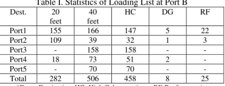
At port B, the ship will discharge some containers and load some other containers. The statistics of the loading list at port B is given in Table 1. After discharging at port B, the ship already has serious stability problem. The stowage plan generation system is used to generate some stowage plans at Port B with better stability before ballast adjustment.
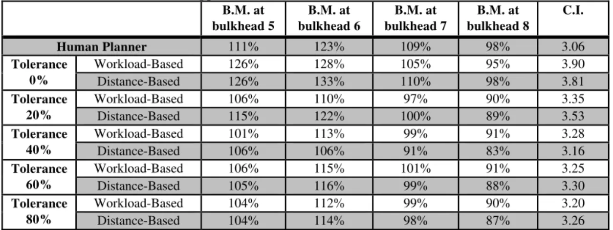
In order to see the effect of different block selection approaches and the tradeoff between C.I. and stability, we generated stowage plan using the two block selection approaches at different tolerance levels. The stowage plan generated by human planner is also provided for comparison. Table 2 shows the statistics of human planner’s stowage plan and plans generated by the system applying different block selection approaches at different tolerance levels. The bulkhead columns show the statistics of bending moment (B.M.) at different sections of the containership. The value indicated the current bending moment (B.M.) at the specific bulkhead as a percentage of the sea-going limit. The objective is to keep these value below 100%, or as low as possible for safe sailing condition. C.I. is shown in the last column.
Each stowage plan applies different block selection approach at a different tolerance level and is generated within 30 seconds on an Intel Core2 PC with 2.66 GHz CPU and 2GB RAM.
Re-handles are not shown in the table as none of the plans generated incurs any re-handle. As can be seen from the
table, the C.I. decreases along with the increase of tolerance level, but stability statistics improve. When the tolerance level go beyond 20%, both block selection approaches result in better C.I. and stability performance than human planner.
Table I. Statistics of Loading List at Port B
Dest. 20 feet
40 feet
HC DG RF
Port1 155 166 147 5 22
Port2 109 39 32 1 3
Port3 - 158 158 - -
Port4 18 73 51 2 -
Port5 - 70 70 - -
Total 282 506 458 8 25
*Dest.- Destination, HC- High Cube containers, RF-Reefer containers, DG-Hazardous Containers, OOG-Out of Gauge cargoes
The stability performance will not always improve when the tolerance level is increased. It is evident from the table that applying the workload-based approach gives better CI than the distance-based approach. However, it is difficult to say which approaches gives better stability performance. It is also affected by the stowage configuration from the previous port. For an extreme example, if the containership is already very heavy at the central part, trying to apply Distance-Based block selection approach will make the ship stability even worse.
Since generating one plan only require less than 30 seconds, we can try different block selection approaches at different tolerance levels to obtain a better stowage plan. This would be very useful to shipping lines in the real commercial world.
VI. CONCLUSION
In this paper, we apply a “Block Selection” heuristics to a stowage plan generation system base on a “block stowage” approach. We proposed two heuristics to take into consideration not only re-handles but also crane intensity and stability when generating stowage plans automatically. This stowage plan generation system exhibits very good performance in terms of plan quality and computational efficiency.
Moreover, we show the tradeoff between crane intensity and ship stability, and the effect of different block selection approaches as well. All of the above are quite useful to improve the quality of stowage planning. In our future work we will refine the system with some container swapping algorithm applying local search method to improve the ship stability further.
ACKNOWLEDGMENT
The study is supported by grants from the Maritime and Port Authority of Singapore and APL.
Table II. Comparison of Human planner’s Stowage plan with Plans Generated by Applying Different Block Selection Approaches at Different Tolerance Levels
B.M. at
bulkhead 5
B.M. at bulkhead 6
B.M. at bulkhead 7
B.M. at bulkhead 8
C.I.
Human Planner 111% 123% 109% 98% 3.06
Tolerance 0%
Workload-Based 126% 128% 105% 95% 3.90
Distance-Based 126% 133% 110% 98% 3.81
Tolerance 20%
Workload-Based 106% 110% 97% 90% 3.35
Distance-Based 115% 122% 100% 89% 3.53
Tolerance 40%
Workload-Based 101% 113% 99% 91% 3.28
Distance-Based 106% 106% 91% 83% 3.16
Tolerance 60%
Workload-Based 106% 115% 101% 91% 3.25
Distance-Based 105% 116% 99% 88% 3.30
Tolerance 80%
Workload-Based 104% 112% 99% 90% 3.20
Distance-Based 104% 114% 98% 87% 3.26
REFERENCES
[1] Ambrosino, D. and Sciomachen, A., 1998. A constraints satisfaction approach for master bay plans, In: Sciutto, G., Brebbia, C.A. (Eds.), Maritime Engineering and Ports. WIT Press, Boston, pp. 155-164. [2] Ambrosino, D., Sciomachen, A. and Tanfani, E., 2004. Stowing a
containership: the master bay plan problem, Transportation Research, 38, pp. 81-99.
[3] Ambrosino, D., Sciomachen, A. and Tanfani, E., 2006. A decomposition heuristics for the container ship stowage problem, Journal of Heuristics, 12,pp. 211- 233.
[4] Aslidis, T., 1989. Combinatorial algorithms for stacking problems, Ph.D. Thesis, MIT.
[5] Aslidis, T., 1990. Minimizing of overstowage in containership operations, Operational Research, 90, pp. 457-471.
[6] Avriel, M., Penn, M., 1993. Exact and approximate solutions of the container ship stowage problem, Computers and Industrial Engineering, 25, pp. 271-274.
[7] Avriel, M., Penn, M., Shpirer, N. and Witteboon, S., 1998. Stowage planning for container ships to reduce the number of shifts, Annals of Operation Research, 76, pp 55-71.
[8] Avriel, M., Penn, M., Shpirer, N., 2000. Containership stowage problem: complexity and connection capabilities, Discrete Applied Mathematics, 103, pp. 271-279.
[9] Delgado A., Jensen Schulte C., 2009. Generating Optimal Stowage Plans for Container Vessel Bays, Principles and Practice of Constraint Programming - CP pp. 6- 20.
[10] Dubrovsky, O., Levitin, G. and Penn, M., 2002. A genetic algorithm with compact solution encoding for the container ship stowage problem, Journal of Heuristics, 8, pp. 585-599.
[11] Imai, A., Miki, T., 1989. A heuristic algorithm with expected utility for an optimal sequence of loading containers into a containerized ship. Journal of Japan Institute of Navigation, 80, pp. 117-124. [12] Wilson, I.D. and Roach, P.A., 1999. Principles of combinatorial
optimization applied to container-ship stowage planning, Journal of Heuristics, 5, pp. 403- 418.
[13] Wilson, I.D. and Roach, P.A., 2000. Container stowage planning: a methodology for generating computerized solutions, Journal of Operational Research Society, 51, pp. 1248-1255.
[14] Wilson, I.D., Roach, P.A. and Ware, J.A., 2001. Container stowage pre-planning: using search to generate solutions, a case study, Knowledge-Based Systems, 14, 3-4, pp. 137-145.