Purpose: We have developed an instrument for computerized surgical videokeratography. A corneal central region of approximately 7.00 mm in diameter may be analyzed, providing the surgeon with information of the power and the astigmatism. Methods: The system is based on a fiber optic Placido disc projecting cone, which is attached to the objective lens of a Zeiss compatible surgical microscope. At the beam splitter we installed a monochromatic high resolution camera. A frame grabber is installed on a PC and images are digitized at a 480x640 resolution. Image processing is used for edge detection of rings. Results: Calibrating curves based on 4 spherical surfaces were generated and approximately 3600 points are calculated for each examination. Preliminary measurements on 10 healthy corneas were compared with those of an EyeSys System 2000 Corneal Topographer. Mean deviation was 0.05 for radius of curvature, 0.24 D for the power and 5.0 degrees for the cylinder. Conclusions: This surgical VKS, with some hardware and software improvements, may be used to reduce residual astigmatisms in conventional cataract and keratoplasty. It could also be used to gather preoperative data in corneal topography assisted LASIK.
Videoceratógrafo para monitoramento da curvatura da córnea durante a cirurgia
* Mantém vínculo com a EyeTec Equipamentos Oftálmi-cos Ltda.(www.eyetec.com.br), empresa que fabrica a versão comercial do instrumento apresentado. 1Pesquisador junto ao IFSC (Instituto de Física de São
Carlos)-USP, Diretor de Pesquisa da Eyetec Equipa-mentos Oftálmicos Ltda.
2Diretores do Departamento de Projetos Mecânico e Eletrônico da Eyetec Equipamentos Oftálmicos. 3Pesquisadora junto ao IFSC (Instituto de Física de São
Carlos)-Universidade de São Paulo e Projetista da Opto Eletrônica S/A.
4Professor do Instituto de Físisca de São Carlos-Univer-sidade de São Paulo.
5Doutor no Setor de Cirurgia Refrativa do Departamento de Oftalmologia da Universidade Federal de São Paulo.
Endereço para correspondência: Av. Dr. Carlos Botelho, 1465 - São Carlos (SP) CEP 13560-250. E-mail: [email protected]
Nota editorial: Pela análise deste trabalho e por sua anuência sobre a divulgação desta nota, agradecemos ao Dr. Milton Ruiz Alves.
Recebido para publicação em 26.03.2001 Aceito para publicação em 20.08.2001
Luis Alberto Vieira de Carvalho1*
Antonio Carlos Romão2
Silvio Tonissi2
Fátima Yasuoka3
Jarbas C. Castro4
Paulo Schor5
Wallace Chamon5
ABSTRACT
INTRODUCTION
be useful because preoperative data would be gathered with the patient in the position that the surgery would take place.
DEVELOPMENT
Basic apparatus
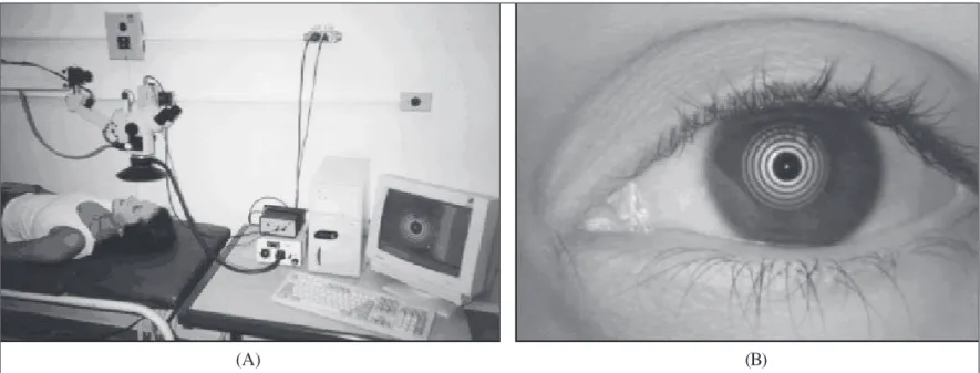
Like nonsurgical VKS, our system is also based on Placi-do’s principle(8). We designed and constructed a high intensi-ty conic concentric ring projecting pattern. This apparatus is attached to the objective lens of an Opto SM-2000 microscope (Rua André Ampére, 153 - 14o andar - Brooklin Paulista\ CEP 04562-080 - São Paulo - SP - Brazil\ Tel. (011) 5506-8284 - Fax (011) 5506-5734) and light reflected off the cornea undergoes two distinct paths: its usual path through the microscope and a second path where the same beam of light is reflected by a beam splitter attached to the microscope’s body. This second path leads the rays so they focus on the 480x640 CCD matrix of an attached monochromatic camera. The CCD grabs the same image seen at the ocular lenses by the surgeon (Figure 1A).
The images are captured and saved in bitmap format on the computer’s hard disc as the surgeon presses a foot switch. A 5V LED (light emitting diode) was adapted at the center of the Placido disc as a fixation point for the patient. During image digitalization the patient’s eye must be aligned with the optic axis of the system. The microscope’s light source must be turned off to avoid surrounding light reflections.
Image processing
Image processing starts right after digitalization. The algo-rithm finds the LED position and from this point starts the
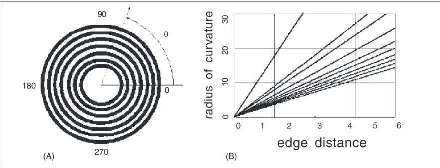
methods that scan the image in horizantal lines and determine edges by difference in the intensity of gray levels. We sug-gest that transforming the Cartesian plane (x,y) of the Placido image in a polar coordinate system (theta, phi) with origin at the LED makes the problem of edge detection straightforward because of the near polar symmetry of the discs. By “scan-ning” the image in the radial direction (Figure 2A) this problem can be reduced to a one dimensional image processing task.
By plotting the intensity of gray level (0-255) for polar angles from 0 to 360 degrees we obtain curves with high and low levels of gray. The portions of higher levels are associa-ted with bright discs on the image, and regions of lower levels are associated with dark discs.
By smoothening these curves to reduce noise and then applying the first derivative to each point, we obtain a second curve where each peak represents the edge between dark and bright discs. We then take the absolute value of each point on this second curve and then apply a line of threshold which determines the edge points. Because we used an algorithm based on calibration curves, the level of thresholding used to determine the edge location can be arbitrarily determined, as long as it is value that allows most of the edge points to be detected.
Calculating radius of curvature and power
Several authors have explored the nontrivial problem of calculating corneal shape based on Placido images. Some insights may be found in(9-17), just to name a few. We will describe here only the method that we used, which may be described as the calibrated sphere algorithm(18) or the look-up table method. Either way, the method is based on images collected from a set of calibrating spherical surfaces and the
Figure 1 - (A) Complete system mounted in our laboratory for preliminary tests prior to installation in the surgery room. (B) Placido disc pattern of our system reflected off the cornea of a volunteer subject
output furnishes axial curvature. A good description of ways in which to calculate other curvatures and the advantages of each one, based on axial curvature, is given in(14,15).
For the calibration data set we used 4 spherical glass surfaces of different radii (7.73, 8.06, 8.34 and 8.91 mm) and measured edges for all of them using the algorithm described above. From this information we used linear regression to construct the graph of radius of curvature versus edge distan-ce shown in Figure 2B. Each line corresponds to the interpola-tion of data from the 4 surfaces, for each edge. Line 1, for example, represents approximation of 4 data points for edge number 1. The other lines in the graph are generated analogo-usly. In this way we found the parameters a and b for the equation of each line (1) and saved these values as ASCII files. r stands for radius of curvature and b stands for distance (in pixels). From each equation one may then calculate radius of curvature for any given edge point of an arbitrary surface. To improve performance of the algorithm we implemented a look-up table of values for each border, containing border distance on one column and radius of curvature on the other. In this ways values may rapidly be accessed.
r = a + b.d
The diopter at each point is calculated using the formula where nc is the index of refraction of the cornea and nair is the index of refraction of the air. For n
c we used the Gullstrand reduced schematic eye index of refraction 1.3375, normally used for keratometers. And for n
air the value 1.000 was used. The denominator is the local radius of curvature in meters.
By using this method several thousand points may be calculated (at most 360x10=3600). We used visualization tech-niques used by most commercial topographers, that is, flat color maps, originally suggested by(12). The curvature data points are interpolated in the radial direction (Figure 5) using cubic splines(19) for each semi-meridian to generate a smooth two dimensional color map. A color table with 15 different colors is associated with variable values of radius of curvatu-re and diopter. The minimal and maximum values of the table vary in accordance to the mean diopter value of data for each examination.
RESULTS
The instrument was originally tested on several spherical surfaces (12 total) different from those used for calibration (radius varying from 6.78 to 8.80 mm). As expected, almost single colored maps were displayed, with approximately cons-tant values of curvature. Mean deviation for radius was 0.02 mm and 0.12 for diopter.
After tests on artificial surfaces, preliminary measurements were made in 10 healthy corneas of 5 adult volunteers (2 females and 3 males, ages between 22 and 45). The procedure was fully explained and formal consent was obtained in all cases. For comparison the same corneas were measured in an EyeSys Corneal Topographer with color map (axial) display. We generated a computer algorithm to read and compare data from the EyeSys topographer with data from our system. By using a small ruler (markings of 10-2 cm) we determined the scale factor of our instrument (pixels/mm) and also that of the EyeSys topographer. We could then precisely determine which region in the topography maps corresponded to our nc - nair
D = r
(A) (B)
Figure 2 - (A) Illustration of the principle used for edge detection of Placido discs. The intensity of gray level is analyzed in the radial direction for each polar angle θθθθθ, from 0 to 360 degrees; (B) set of 10 calibration curves generated from edge information of the spherical shapes. Radius
and distance are in mm
(A) 270
180
90
0
0 θ
radius of cur
v
a
ture
0
10
20
30
0 1 2 3 4 5 6
point. In figures 3 and 4 we show two cases for visual compa-rison of results.
Quantitative results were as follows: mean deviation in radius of curvature for all examinations was less than or equal to 0.05 mm for 8 cases. Corneal astigmatism deviations were less than or equal to 0.18 D for 7 of all cases. For cylindrical axis deviation was less than or equal to for 5 degrees for 6 of all cases. Mean time for each examination was 14.3 s, including image processing and generation of color map. Graphs of curvature versus polar angle for a specific radial distance were also implemented. These provide a simple and fast way for the surgeon to analyze the astigmatism of the surface at a specific region.
DISCUSSION
In this article we describe the development of a novel instrument, which may be described as a surgical VKS. Prelimi-nary tests on healthy corneas indicate that the instrument may be applied in diminishing post-astigmatisms common to sur-geries such as cataract and corneal transplant. We should point out that there are new techniques for cataract surgery that need only small incisions and therefore cause little distor-tion after sutures, but in many countries the tradidistor-tional techni-que is still in use. We should also notice that there are cases of corneal transplant where the cornea becomes so distorted that the Placido discs are virtually impossible to analyze.
Other possible applications should be in surgeries that use intrastromal rings to correct refractive errors(20), making it pos-sible to determine more precisely how many diopters were corrected; and in topography assisted LASIK surgeries(7).
is based on the polar symmetry and good contrast of the Pla-cido discs. It requires only one mouse click and takes only about 4 s. Other systems require several user clicks(5). The system is also very easy to maintain and install and may also work on a regular Notebook PC, provided that the compatible hardware is used. This adds a great deal of convenience in terms of carrying the system to different surgery rooms. Surge-on’s opinions during the examination process was that the system is quite easy to mount and use, but modifications sho-uld be introduced so the process wosho-uld not require mouse clicks and attention with software manipulation during surgery. Some improvements to the system should include: a smal-ler Placido disc system to improve the surgeon’s freedom when accessing the patients eye with surgical tools; a method that provides correct alignment of the patient’s head, to avoid wrong axis measurements and even to account for cyclotor-sion of the eye globe; attachments of more rings at the center of the Placido disc in such a way that the 1.5 mm central region can be mapped with more accuracy.
ACKNOWLEDGMENTS
We would like to thank the Escola Paulista de Medicina -UNIFESP for providing the room in which we installed and tested the system, and also for allowing us to use their Eyesys System. We would like to thank Professor Stanley Klein, Ph.D., Thom Carney, Ph.D., Corina van de Pol, Ph.D., and John Cor-zine, O.D., from the School of Optometry, University of Ca-lifornia at Berkeley, for their tremendous help and interesting ideas. We would also like to thank the following institutions for
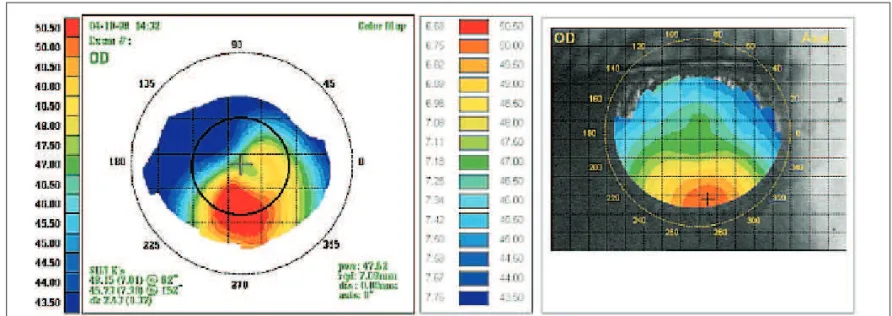
Figure 3 - Comparison of color maps for a subject with with-the-rule astigmatism. In this case we notice that the correct positioning of the patient’s head is critical for obtaining correct values for astigmatic axis. There is a slight difference in axis from the EyeSys map due to misalignment. We also notice that, because our Placido disc system does not have central mires (a limitation imposed by the diameter of the microscope’s objective lens), the central portion of our map (approximately 1.5 mm in diameter) has constant color (lack of the “hour glass” pattern) when
Figure 4 - A volunteer with keratoconus. We have manually edited a black circle in the EyeSys map to designate the corresponding area mapped by our system. We notice in our examination that the keratocone region was detected but not totally, and this is due to our limitation to a 7.00 mm diameter region, smaller than the EyeSys mapping region (9-11 mm). We may notice the visual similarities in shape and the quantitative
similarities in diopter values
financial support: FAPESP (Fundação de Amparo à Pesquisa do Estado de São Paulo - Brazil, CNPq - Conselho Nacional de Desenvolvimento Científico e Tecnológico - Brazil).
RESUMO
Objetivo: Os autores desenvolveram um videoceratógrafo pa-ra uso dupa-rante a cirurgia. Uma região centpa-ral da córnea de aproximadamente 7,00 mm de diâmetro pode ser analisada, fornecendo informação ao cirurgião sobre poder dióptrico e astigmatismo. Métodos: O sistema é baseado em discos de Plácido em forma cônica, iluminados por uma fonte de luz construída com fibras ópticas. O cone é acoplado à lente objetiva de um microscópio padrão Zeiss. Uma placa de captu-ra é instalada num microcomputador IBM compatível e ima-gens de Plácido são digitalizadas numa resolução de 640x480 pontos. Processamento digital das imagens é utilizado para detecção dos discos de Plácido. Resultados: Curvas de cali-bração baseadas em 4 esferas foram geradas e aproximada-mente 3600 valores de poder dióptrico são computados para cada exame. Exames preliminares em 10 córneas sadias foram comparados com exames nos mesmos olhos feitos num Video-ceratógrafo Eyesys System 2000. O desvio médio padrão foi de 0,05 mm para o raio de curvatura, 0,24 dioptrias para o poder e 5 graus para o cilindro. Conclusões: Este videoceratoscópio cirúrgico poderá ser utilizado para reduzir o astigmatismo resi-dual em procedimentos convencionais de catarata e cerato-plastia. Poderá também ser utilizado para colher dados imedia-tamente anteriores às em cirurgias refrativas (PRK e LASIK).
Descritores: Topografia da córnea; Ceratometria; Discos de Plácido
REFERENCES
1. Sanders, Donald R, Koch, Douglas D. An atlas of corneal topography. 2nd ed. New Jersey: Slack; 1993.
2. Troutman RC, Buzard KA. Corneal astigmatism. 3rd ed. St. Louis: Mosby Year Book; 1989.
3. Troutman RC, Kelly S, Kaye D, Clahance AC. The use and preliminary results of the Troutman Surgical Keratometer in cataract and corneal surgery. Trans Am Acad Ophthalmol Otorarygol 1977;83:232-8.
4. Amoils SP. Intraoperative Keratometry with the oval comparator (Astigmo-meter). Br J Ophthalmol 1986;70:708-11.
5. Igarashi H, Kojima M, Igarashi S, Yoshida A, Cheng HM. A simple and effective video keratometric system. Acta Ophthalmol. Scand 1995;73:336-9. 6. Troutman RC. Surgical keratometer in the management of astigmatism in
keratoplasty. Ann Ophthalmol 1987;19:473-4.
7. Wiesinger-Jendritza B, Knorz MC, Hugger P, Lierman A. Laser in situ keratomileusis assisted by corneal topography. J Cataract Refract Surg 1998; 24:166-74.
8. Placido A. Novo instrumento de exploração da cornea, Periodico d’Oftalmo-lógica Practica, Lisboa 1880;5:27-30.
9. Mandell RB, St Helen R. Mathematical model of the corneal contour. Br J Physiol Optics 1971;26:183-97.
10. Mandell RB. The enigma of the corneal contour. CLAO J 1992;18:267-73. 11. Mammone RJ, Gersten M, Gormley DJ, Koplin RS, Lubkin VL. 3D Corneal
modeling system. IEEE Trans Biomedical Eng 1990;37:66-73.
12. Klyce SD. Computer-assisted corneal topography, high resolution graphics presen-tation and analyses of keratoscopy. Invest Ophthalmol Vis Sci 1984;25:426-35. 13. Klein SA. A corneal topography algorithm that produces continuous curvature.
Optom Vis Sci 1992;69:829-34.
14. Klein SA, Mandell RB, Shape and refractive powers in corneal topography. Invest Ophthalmol Vis Sci 1995;36:2096-109.
15. Klein SA, Mandell RB. Axial and instantaneous power conversion in corneal topography. Invest Ophthalmol Vis Sci 1995;36:2155-9.
16. van Saarlos, Paul P, Constable IJ. Improved method for calculation of corneal topography for any photokeratoscope geometry. Am Acad Optometry 1991; 68:960-5.
17. Halstead MA, Barsky BA, Klein SA, Mandell RB. A spline surface algorithm for reconstruction of corneal topography from a videokeratographic reflection pattern. Optom Vis Sci 1995;72:821-7.
18. Halstead Mark A. Efficient techniques for surface design using constrained optimization. [Dissertation]. Berkeley: University of California; 1996. 19. Barsky BA. Computer graphics and geometric modeling using Beta-splines.
New York: Springer-Verlag; 1988.