Adaptive LCMV Beamforming Avoiding DOA
Estimation for Packet-like Wireless Systems
Danilo Zanatta Filho, Charles Casimiro Cavalcante and Jo˜ao Marcos Travassos Romano
DSPCOM, UNICAMP, Campinas SP, Brazil
Abstract — A new adaptive LCMV solution that avoids DOA estimation for uplink beamforming is proposed. The use of the uplink channel covari-ance matrix (UCCM) instead of DOA estimation is shown to be a suitable alternative for constraints selection. The resulting LCMV adaptive solu-tions are then based on the LMS and RLS versions with the UCCM esti-mation. The new method is then evaluated for packed-like wireless systems through computational simulations.
I. INTRODUCTION
Signal detection is a very interesting field in mobile commu-nications due to the importance of correctly recovering the de-sired signal. This detection can be performed both in the uplink and downlink. However, due to some system features, the de-tection in uplink profits by the use of smart antennas.
In the uplink context of a mobile communication system, where several users share the same resources, an important strat-egy to separate the signals of interest is the use of beamforming techniques. Some works have proposed the use of such a strat-egy with decoupled space-time processing [1]. The approach consists in providing interference cancelling by means of spa-tial processing, so that the recovered signal be feed into a tem-poral equalizer, since this signal is still subject to intersymbol interference (ISI).
In a previous work [2], two different optimization criteria for beamforming have been investigated: the so-called Linearly
Constrained Minimum Variance (LCMV) and the Summed In-verse Carrier to interference Ratio (SICR). SICR demands an
a priori knowledge about the uplink channel covariance matrix (UCCM), while LCMV needs a previous estimation of the angle or direction of arrival (DOA) of the desired users. One interest-ing result of [2] states that when one sinterest-ingle eigenvectorial con-straint (EV) is used in the LCMV solution, the performance of both criteria (LCMV and SICR) are practically the same. How-ever, LCMV provides adaptive solutions for performing beam-forming.
The use of an adaptive approach is particularly interesting, since in a mobile system the users’ characteristics can vary in according to the employed strategy. For instance, frequency hopping (FH) is a strategy for interference reduction largely ap-plied in practical wireless systems. From one slot to another the spatial interference pattern of the desired user changes, since the mobile user that shares the same frequency of the desired user changes every slot. Slotted-packet networks causes the same change in the spatial interference pattern since users transmit The authors are with the Digital Signal Processing for Commu-nications (DSPCOM) laboratory, UNICAMP, Campinas - SP, Brazil. Phone: +55 19 3788 3702 Fax: +55 19 3289 1395. E-mails: {daniloz,charles,romano}@decom.fee.unicamp.br
This work was supported by the Ericsson Research Brazilian Branch under the ERBB/UNI.33 technical cooperation contract.
over time slots sorted randomly (S-Aloha networks) [3]. Both previously mentioned situations can be seen as
packet-like wireless systems since the spatial interference pattern can
suddenly change. In such systems, the tracking capability is a highly important issue in the design of good signal detection strategies.
In the present work, the application of the LCMV adaptive solutions (namely LMS and RLS) is investigated and compared with the LCMV batch solution. Also, an alternative strategy concerning the implementation of the adaptive LCMV algo-rithm with EV constraint is proposed. It consists in using the UCCM, instead of DOA estimation, for constructing the matrix of constraints to be applied in the adaptation process. Simu-lations are performed for different scenarios of user speed in a packet-like environment, in order to evaluate the performance of the proposed method.
The rest of the paper is organized as follows. Section II is de-voted to a recall on the batch solutions of the LCMV and SICR optimization criteria. Section III presents the novel LCMV method, which avoids DOA estimation by using UCCM to con-struct the matrix of constraints. Section IV shows the formu-lation of the corresponding adaptive versions of the proposed method. Section V presents simulations results to illustrate our analyze. Finally, conclusions are stated in Section VI.
II. RECALLS ONSICRXLCMV BATCHSOLUTIONS Here we present some recalls about the most important char-acteristics of the constrained criteria shown in [2], in order to provide some background about them.
A. SICR Solution
The SICR was initially proposed by Zetterberg in [4] and dis-cussed by Ast´e in [5] as a downlink criterion for the maximiza-tion of the carrier-to-interference ratio (CIR), for all co-channel mobile users. However, the resolution of the downlink prob-lem also leads to the determination of the uplink beamforming weights, as shown in [6].
In this work, we will use the SICR solution in uplink, where the beamforming weights can be independently performed as follows:
wk = arg max
wk
wH k Rkwk wH
k Rk,intwk
(1) whereRk is the uplink channel covariance matrix (UCCM) of thekth user andRk,int = R−Rk = P
i,i6=k
Ri+σ2nI is the
vector for the kth user andσ2
n is the thermal noise power per antenna element at the base station.
This minimization procedure can be solved by using La-grange multipliers. The solution is the unit norm generalized eigenvector of(Rk,Rk,int)corresponding to the largest
eigen-value. Such criterion also corresponds to wk = arg min
wk
©
wHkRwkª ¯¯wHk Rkwk =c (2) wherecis an arbitrary constant.
B. LCMV Solution
The LCMV criterion minimizes the output power of the beamformer under the constraint of fixed gains in some given values of DOA. So the array is set to receive from the desired user while minimizing interferers arriving from other directions. This criterion is expressed by:
wk= arg min
wk
©
wHkRwkª ¯¯CHk wk=fk (3) whereCk is the matrix of constraints for thekth user andfk is the response vector for thekth user.
Such method just takes into account the corresponding DOAs for each user by introducing point constraints for each direction. The matrixCkis then formed as follows:
Ck =£ d(θk,1) d(θk,2) · · · d(θk,L) ¤ (4) whered(θk,l), which has dimensionM×1, is the steering vec-tor corresponding to thelth considered DOA of userk,Lis the number of constraints andMis the number of antenna elements. The response vector is given by:
fk= £
1 √γk,2 · · · √γk,L ¤ T
(5) whereγk,l is the relative power of thelth path with respect to the first one, for userk.
Thus, this approach requires the knowledge of both DOA and power for each user multipath, in order to construct the con-straints. Besides, in order to deal with non-null angular spread, two types of constraints may be posed:
• Point constraints: a number of point constraints is inserted in the angle bandwidth. This approach is limited due to the number of degrees of freedom, which depends on the number of anten-nas in the array [2].
• Eigenvectorial constraints (EV): cope with the number of
de-grees of freedom by using the most significative singular vec-tors (associated with the most significative singular values) of the matrix of constraints.
The resultant criterion for the LCMV with EV, denoted by LCMVEV, is given by the singular value decomposition of the
matrix of constraints used in (3).
Previous simulation results [2] have shown that the use of only one EV (called EV1) provides better results. Figure 1 shows the performance in terms of SNIR (Signal to Noise plus Interference Ratio). The CDF (SNIR) states for the cumulative function distribution of SNIR. It means the probability of the SNIR be lower than or equal to a given value (in the horizontal axis). So, better performance results are represented by curves located more to the right side.
21 22 23 24 25 26 27 28 29
0 0.1 0.2 0.3 0.4 0.5 0.6 0.7 0.8 0.9 1
SNIR [dB]
CDF (SNIR)
LCMV EV1 SICR
AS=1o AS=5o AS=10o
Fig. 1. Comparison between the SICR andLCMVEV1forAS = 1◦,5◦and 10◦.
III. LCMVAVOIDINGDOAESTIMATION
In order to compute the eigenvectorial constraint, the matrix of constraints is formed by the directional vectors corresponding to the estimated DOA of the desired signals, as stated in equa-tion (4). Then, the singular value decomposiequa-tion (SVD) may be directly applied to the matrix of constraints so that a more simple representation ofCH
k be given by:
CHk =Uk ·
Σk 0P×(M−P)
0(L−P)×P 0(L−P)×(M−P)
¸
VHk (6) with
U=£ u1 u2 · · · uL ¤L×L
V=£ v1 v2 · · · vM ¤M×M
Σ= diag (σ1, σ2, . . . , σP)
(7)
whereUandVare unitary matrices, which contain respectively the left and right singular vectors; andΣis a diagonal matrix composed by the singular values ofCHk sorted asσ1 ≥σ2 ≥
. . .≥σP >0.
As mentioned before, the best performance is obtained with the use of only one eigenvectorial constraint [2]. That is, with the use of the singular vector associated with the maximum sin-gular value. Thus, the EV constraint and the corresponding re-sponse element are:
e Ck=v1
efk=
1
σ1
uH1 fk
(8)
It is important to highlight thatv1is the eigenvector
associ-ated with the maximum eigenvalue ofCkCH
k . This matrix can be written as follows:
CkCHk = L X
l=1
TABLE I LCMV-LMS
• Initialization
wk(0) =qk (11)
• Update the antenna weights
wk(n+ 1) =Pk[wk(n)−µy(n)x(n)] +qk (12)
It is worth to notice the similarity between this matrix and the UCCM matrix of thekth user:
Rk =
LT
X
l=1
g(θk,l)dH(θk,l)d(θk,l) (10)
whereg(θk,l)is the mean power of the received signal in direc-tion θk,l andLT is the total number of multipaths linking the mobilekand the base station.
Moreover, as far as the number of considered DOAsLin (4) and (9) becomes greater and close toLT, the constraints will better express the spatial channel between the base station and the mobile. This leads to a better performance for the LCMV solution.
Therefore, we propose to take the UCCM matrix in (10) as the best representation of CkCHk. So, the EV constraint Cek in (8) becomes the eigenvector associated with the maximum eigenvalue of the matrixRkand the response elementefkcan be set to an arbitrary value.
Hence, the LCMV without DOA estimation solution, so-called LCMVCM (LCMV Covariance Matrix), consists of the
following steps for each userk: 1. Estimation ofRk
2. Computation ofCek, the eigenvector associated with the max-imum eigenvalue ofRk.
3. Computation of the beamforming weight: wk=R−1Cke ³CeH
k R−1Cke ´−1
, whereefk was set to1. IV. ADAPTIVELCMV
The results of our previous work [2] motivated the investi-gation of the performance of adaptive versions of the LCMV criterion, since they may be more suitable for tracking changes in the channel parameters. Furthermore, the LCMVCMsolution
was used in order to derive the adaptive solutions since such a solution avoids DOA estimation, which has high computational complexity.
A. LCMV-LMS
The LMS adaptive version of the LCMV criterion was firstly proposed by Frost in [7] and uses an instantaneous estimation of the total covariance matrixR.
This algorithm is shown in Table I for userk, wherex(n)is the sampled signal at the antenna at instantn,y(n)is the array output defined by y(n) = xH(n)wk(n), while the vectorqk
and the matrixPkare defined by: qk ,Cke ³CeHk Cke
´−1
efk (13)
Pk ,I−Cek ³
e CH
kCek ´−1
e CH
k (14)
B. LCMV-RLS
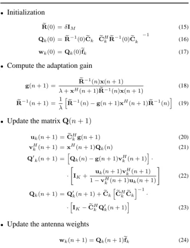
The RLS version of the LCMV criterion was proposed by Resende et al. in [8]. The algorithm is initialized by posing the covariance matrix as a diagonal one and then obtaining the initial values for the antenna weights, in according to the LCMV criterion. Afterwards, the weights are computed as indicated in Table II for user k. More considerations on the role of each intermediary variable in such summarized table can be found in [8].
TABLE II LCMV-RLS
• Initialization
e
R(0) =δIM (15)
Qk(0) =Re−1(0)Cek
e CHkRe−
1 (0)Cek
−1
(16)
wk(0) =Qk(0)efk (17)
• Compute the adaptation gain g(n+ 1) = Re−
1
(n)x(n+ 1) λ+xH
(n+ 1)Re−1(n)x(n+ 1) (18) e
R−1
(n+ 1) = 1 λ h
e R−1
(n)−g(n+ 1)xH
(n+ 1)Re−1
(n)i (19)
• Update the matrixQ(n+ 1) uk(n+ 1) =Ce
H
kg(n+ 1) (20)
vkH(n+ 1) =x H
(n+ 1)Qk(n) (21)
Q′
k(n+ 1) =
h
Qk(n)−g(n+ 1)v H k(n+ 1)
i
·
·
" IK+
uk(n+ 1)vHk(n+ 1) 1−vH
k(n+ 1)uk(n+ 1)
#
(22)
Qk(n+ 1) =Q′k(n+ 1) +Cek
h e CHkCek
i−1
·
·hIK−Ce H
kQ′k(n+ 1)
i
(23)
• Update the antenna weights
wk(n+ 1) =Qk(n+ 1)efk (24)
V. SIMULATIONS
Moreover, the simulations are carried in a GSM context with an uplink carrier frequency fc=2 GHz, a symbol rate
Rs=T1
s=270.833Mbauds and a raised cosine filter, with roll-off
0.35, for both transmitter and receiver filters.
The base station has a3element antenna array, withλc
2
inter-element distance, used to perform purely spatial processing as mentioned before. This leads to a higher SNIR in the temporal equalizer input.
The space-time channel between each user and the array is modelled as composed by 4 multipaths as described in Table III, where the DOAs are given in degrees. The SNR (Signal to Noise Ratio) for each antenna element was set to20dB.
Firstly, we have tested the LCMVCM to verify its
perfor-mance when compared to the LCMVEVsolution. These
simu-lations were carried out in a static environment (without fading) and0◦of angular spread. The total covariance matrixRwas
es-timated over7000symbols and the users’ UCCM was supposed to be known. As expected, the results have shown that the use of the UCCM matrix instead of the matrix of constraints leads to an equivalent performance. Figure 2 shows the reception radiation pattern for the previously mentioned channel.
−80 −60 −40 −20 0 20 40 60 80
−50 −40 −30 −20 −10 0 10
Azimuth Angle [degrees]
Gain [dB]
User 1 User 2
Fig. 2. Reception radiation pattern for LCMVCMmethod.
Two distinct cases were chosen to evaluate the adaptive ver-sions of LCMVCM in presence of fading or in a packet-like
transmission.
A. Fading
The Jakes’ model [9] is used in the non-static environment, so that fading is independently inserted in each multipath, for which the respective values of delay, DOA and mean power are
TABLE III
SPACE-TIMECHANNELPARAMETERS.
Parameter User 1 User 2
Delay (×Ts) 0 0.5 1 2 0 0.5 1 2
DOA 0 10 20 30 -40 -30 -20 -10
Mean power 0.45 0.4 0.1 0.05 0.45 0.4 0.1 0.05
0 5000 10000 15000
0 5 10 15 20 25
samples
SNIR [dB]
0 5000 10000 15000
0 5 10 15 20 25
samples
SNIR [dB]
User 1
User 2
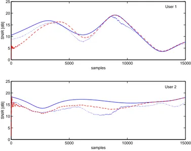
Fig. 3. Comparison between LCMVCM Batch Solution (solid lines),
LCMVCM-LMS (dotted lines) and LMCVCM-RLS (dashed lines) for 15 km/h.
assumed to be as stated in table III. The total covariance matrix Rwas estimated over15000symbols for the batch solution and the users’ UCCM was supposed to be known for all solutions.
Figure 3 shows the SNIR evolution for the two users, each one with a speed of 15 km/h and 3◦ of angular spread.
The LCMVCM-LMS convergence factor wasµ = 5· 10−4.
The LCMVCM-RLS convergence parameters were δ=10 and
λ=0.999999. As it can be seen, the RLS version slightly out-performs the LMS one. Both tracks the channel variations due to fading, but the LMS version has a poorer tracking capability and a higher misadjustment.
Figure 4 shows the SNIR evolution for both users, now with a speed of 100 km/h. The other parameters were the same as in the previous case. Once again, the RLS version sightly outper-forms the LMS one, with a better tracking capability. Due to the instantaneous estimation of the adaptive algorithms, they have a better performance than the batch solution in some intervals of time.
It is worth to mention that the convergence parameters were chosen in order to provide good performance in both situations, i.e. 15 km/h and 100 km/h. Although, these parameters could be adjusted in each case to improve the performance.
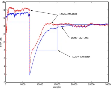
B. Packet-like simulations
In this case, a sudden change in the interferer characteristics is forced in a given time instant. This change concerns the inter-ferer’s DOAs. As previously mentioned in Section I we call in this paper packet-like system both FH or slotted-packet systems. Simulations were carried out in a static environment but with 3◦ of angular spread. At 7000 samples the
inter-ferer’s multipath DOAs changed from[−40,−30,−20,−10]to
[−10,−3,40,60], while all other channel parameters remains the same.
Figure 5 shows the SNIR evolution of the LCMVCM batch
solution for the desired user, LCMVCM-LMS and LCMVCM
0 5000 10000 15000 −5
5 15 25
samples
SNIR [dB]
0 5000 10000 15000
−5 5 15 25
samples
SNIR [dB]
User 1
User 2
Fig. 4. Comparison between LCMVCM Batch Solution (solid lines),
LCMVCM-LMS (dotted lines) and LMCVCM-RLS (dashed lines) for 100
km/h.
matrixRfor the batch solution was done each15000samples. The desired user’s UCCM was again assumed to be known. Pa-rameters µ=10−3 for the LMS version andδ=10andλ=0.999
for the RLS one were used.
The batch solution has two sudden changes in the SNIR level, the first one (at7000) is due to the interferer channel change and the second (at15000) corresponds to the second window used for estimating total covariance matrix.
As it can be seen in figure 5, the adaptive solutions are able to track variations in the interference pattern, becoming more suitable than the batch solution.
0 5000 10000 15000 20000 25000 30000 0
2 4 6 8 10 12 14 16 18 20
samples
SNIR [dB]
LCMV−CM−RLS
LCMV−CM−LMS
LCMV−CM Batch
Fig. 5. Comparison between LCMVCMBatch Solution, LCMVCM-LMS and
LMCVCM-RLS in a packet-like context.
VI. CONCLUSIONS
In this paper a novel approach based on the LCMV criterion that avoids DOA estimation was proposed. Eigenvectorial straints have allowed the use of an alternative matrix of con-straints formed by the maximum eigenvector of the estimated uplink channel covariance matrix. The proposed approach pro-vides a better criterion since the use of the uplink covariance matrix brings to the method more information about the spa-tial channel than DOA estimation. Besides, high computational complexity algorithms for DOA estimation are replaced by low complexity covariance matrix estimation.
Moreover, both LMS and RLS adaptive versions of this novel approach were studied and investigation about the performance evaluation of the proposition was done in a packet-like wire-less system. Simulations have shown that adaptive versions could outperform batch solutions in the situations where the in-terferers’ characteristics change suddenly, as in FH systems or slotted-packet systems.
REFERENCES
[1] C. M. Panazio and F. R. P. Cavalcanti, “Decoupled Space-Time Processing: Performance Evaluation for TDMA Cellular,” in Proceedings of SBrT’01, Fortaleza, CE - Brazil, September 2001.
[2] D. Zanatta Filho, C. C. Cavalcante, J. M. T. Romano, and L. S. Resende, “An LCMV-Based Approach for Downlink Beamforming in FDD Sys-tems in Presence of Angular Spread,” in Proceedings of EUSIPCO 2002, Toulouse, France, September 2002.
[3] Matthew D. Orange, Packetised Wireless Communication Systems in
Inter-ference Limited Environments, Ph.D. thesis, University of Auckland, New
Zealand, 1998.
[4] P. Zetterberg, Mobile Cellular Communications with Base Station Antenna
Arrays: Spectrum Efficiency, Algorithms and Propagation Models, Ph.D.
thesis, Royal Institute of Technology, Stockholm, Sweden, 1997.
[5] T. Ast´e, M´ethodes de traitement d’antenne adaptatives pour un syst`eme de
communications num´eriques radiomobiles de type GSM, Ph.D. Thesis (in
French), Conservatoire National des Arts et M´etiers, Paris, France, Decem-ber 1998.
[6] D. Zanatta Filho and L. F´ety, “A Fast Algorithm for Joint Downlink Beam-forming and Power Control in UMTS Systems,” in Proceedings ITS 2002, Natal, Brazil, September 2002.
[7] O. L. Frost III, “An Algorithm for Linearly Constrained Adaptive Array Processing,” Procedings of the IEEE, vol. 60, no. 8, pp. 926–935, August 1972.
[8] L. S. Resende, J. M. T. Romano, and M. G. Bellanger, “A Fast Least-Squares Algorithm for Linearly Constrained Adaptive Filtering,” IEEE Trans. on Signal Processing, vol. 44, no. 5, pp. 1168–1174, May 1996.