ISSN 1549-3636
© 2007 Science Publications
Corresponding Author: S.Sudha, Government College of Technology, Coimbatore-641 013, India
454
Wavelet and ANN Based Relaying for Power Transformer Protection
1
S.Sudha and 2A. Ebenezer Jeyakumar
1
Government College of Technology, Coimbatore-641 013, India
2
Government College of Engineering, Salem-636 011, India
Abstract: This paper presents an efficient wavelet and neural network (WNN) based algorithm for distinguishing magnetizing inrush currents from internal fault currents in three phase power transformers. The wavelet transform is applied first to decompose the current signals of the power transformer into a series of detailed wavelet components. The values of the detailed coefficients obtained can accurately discriminate between an internal fault and magnetizing inrush currents in power transformers. The detailed coefficients are further used to train an Artificial Neural Network (ANN). The trained ANN clearly distinguishes an internal fault current from magnetizing inrush current. A typical 750 MVA, 27/420KV, /Y power transformer connected between a 27KV source at the sending end and a 420KV transmission line connected to an infinite bus power system at the receiving end were simulated using PSCAD/EMTDC software. The generated data were used by the MATLAB software to test the performance of the proposed technique. The simulation results obtained show that the new algorithm is more reliable and accurate. It provides a high operating sensitivity for internal faults and remains stable for inrush currents of the power transformers.
Key Words: Power Transformer, Differential Protection, Wavelet Transform, Artificial Neural Network.
INTRODUCTION
Power transformer is one of the most essential elements in the power system. Power transformer functions as a node to connect two different voltage levels. Therefore, the continuity of the transformer operation is of vital importance in maintaining the reliability of power system. Any unscheduled maintenance, especially replacement of faulty transformer is very expensive and time consuming. In order to detect faults, high speed, highly sensitive and reliable protective relays are required.
For this purpose, differential protection has been employed as the primary protection for most of the power transformers. Differential protection is based on the fact that any fault within an electrical equipment would cause the current entering it, to be different from that leaving it. Thus, we can compare the two currents either in magnitude or in phase or both and issue a trip output if the difference exceeds a predetermined set value. This method is very attractive when both the ends of the apparatus are physically near each other.
A differential scheme is supposed to respond only to internal faults and restrain from tripping on inrush currents and external faults. The differential current is small for external and normal operating conditions. The
differential current becomes significant for internal faults, the relay operates if the difference exceeds a predetermined set value.
When an unloaded transformer is energized, the primary windings draw large magnetizing inrush current from the power system. As this current flows only on the primary side of the transformer, it looks like an internal fault to the differential scheme and ends up as spill current and the relay maloperates. Distinguishing an inrush current from an internal fault current is still a challenging Power Transformer Protection problem. The inrush waveform is rich in harmonics whereas the internal fault consists of the fundamental and small amount of second harmonics. Conventional transformer protection schemes use second harmonic component as the discriminator factor between an inrush and internal fault current [1].The main drawback of this approach is during CT saturation, the second harmonic component may also be generated during internal faults and the new low-loss amorphous materials in modern Power transformers may produce low second harmonic content in inrush current [2].
applied to single phase power transformer protection to distinguish internal faults from magnetizing inrush currents [7, 8]. However the above techniques are based on either time or frequency domain signal and not both time and frequency features of the signal.
The wavelet transform is a new and powerful tool which can extract information from the transient signals simultaneously in both the time and frequency domains unlike Fourier Transform which can only give the information in the frequency domain .Wavelet transforms have been extensively used for analyzing the transient phenomena in a Power transformer for distinguishing internal fault currents from inrush currents [9-10].
Wavelet transform combined with Artificial Neural Network (ANN) have been implemented for this purpose [11-13].
This paper proposes a new wavelet and ANN based three phase transformer protection algorithm to distinguish inrush currents from internal fault currents in three phase power transformers. The proposed algorithm extracts fault and inrush generated transient signals using Discrete Wavelet Transform (DWT). The signals are then tuned by DWT multi resolution filter bank. The detail 1 coefficients (d1) of the transient signals are got by the decomposition using DWT. DWT has considerably reduced the volume of input data of the ANN without any loss of information. The d1 coefficients of transient signals of various fault and inrush currents are used to train a feed forward neural network. The ANN architecture has 3 inputs, 10 first hidden layer neurons, 20 second hidden layer neurons and one output. Finally, the wavelet and ANN based relay clearly classifies whether the fault is an internal fault or inrush current.
Extensive simulation studies have been conducted using PSCAD/EMTDC software to verify the feasibility of the proposed protection scheme for inrush currents at different voltage closing angles and various types of internal faults such as single phase to ground faults, double phase to ground faults, three phase to ground faults, two phase faults and three phase faults.
Analysis reveals that the technique is able to clearly distinguish an inrush current from a fault condition reliably and accurately and avoids relay maloperation during inrush currents.
Wavelet Transform: DWT is an ideal way to capture the transient phenomena for transformer.The wavelet transform gives the frequency information of the signal and also the times at which these frequencies occur. Combining, these two properties make the Fast Wavelet Transform (FWT), an alternative to the conventional Fast Fourier Transform (FFT). Wavelet is a waveform of limited duration. Wavelets tend to be irregular, asymmetric, short and oscillatory waveforms.
To detect the transformer faults, only dominant transients within the certain bands play the important role. Therefore the wavelet filter banks are designed to extract the required transient currents. DWT is capable of extracting both fast and slow events in a desired resolution. The DWT of a signal x is calculated by passing it through a series of filters. First the original signal x[n] is passed through a half band low pass filter with impulse response g[n], resulting in a convolution of the two.
( 1 ) where x is the signal in discrete time function., the sequence is denoted by x[n], n is an integer, g[n] is the impulse response of the low pass filter and y[n] is the output of the filter.
The signal is also decomposed simultaneously using a half band high-pass filter h[n]. The outputs from the high pass filter give the detail coefficients and the outputs from the low-pass filter give the approximation coefficients. It is important that the two filters are related to each other and they are known as a quadrature mirror filter. However, since half of the frequencies of the signal have now been removed, half the samples can be discarded according to Nyquist’s rule. The filter outputs are then downsampled by 2.Hence the equation 1 becomes,
( 2 )
( 3 ) This decomposition has halved the time resolution since only half the number of samples now characterizes the entire signal. However, this operation doubles the frequency resolution, since the frequency band of the signal now spans only half the previous frequency band. The Block diagram of filter analysis is shown in figure1.
Neural Networks: The ANN is an exact simulation of a real nervous system. A multi layered Feed Forward Neural Network (FFNN) consists of an input layer, an output layer and one or more hidden layers between its input and output layer. Each layer consists of certain number of neurons. Back propagation algorithm is commonly used for training multi layer FFNN. It can be used to solve complex pattern-matching problems.
Network learns a pre-defined set of input-output training pairs by using a two phase propagate-adapt cycle. The applied input pattern to the first layer propagates through each upper layer until an output is generated. This output pattern is compared with the desired output and an error signal is computed for each output unit. The error signals are then transmitted backward from the output layer to each node in the intermediate layer. This process repeats layer by layer. Based on the error signal received, the connection weights are updated to cause the network to converge toward a state that allows all the training patterns to be encoded. After training, when presented with an arbitrary input pattern, the network will respond with an active output if the new input contains a pattern that resembles the feature the individual units learned to recognize during training.
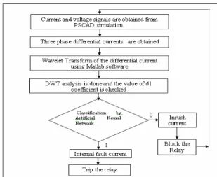
Proposed algorithm: The flowchart of the proposed algorithm is shown in fig. 2 and is explained in steps.
Step 1: The current and voltage signals are obtained from the three phase transformer using PSCAD / EMTDC software for different types of fault and inrush currents.
Step 2: The differential currents of the transformer are calculated.
Step 3: Wavelet transform of the three phase differential currents are obtained using MATLAB software.
Step 4: The DWT analysis of the differential current is studied.
Step 5: The detail coefficients of the signal are obtained.
Step 6: Nature of the transient spikes in the DWT analysis and the value of the Detail coefficients and spectral energy determines whether the current is an inrush or internal fault current.
Step 7: The d1 coefficients of different fault and inrush currents are fed to ANN and trained.
Step 8: Wavelet based ANN relay distinguishes internal fault current from inrush current.
Fig. 2: Flowchart of the proposed Algorithm.
Simulation Model: A Part of power system consisting of a power transformer connected to an alternator and an infinite Busbar is modelled using PSCAD/EMTDC software to obtain the required current signals for investigation of the proposed algorithm.
A power system consisting of a 27KV source,
three phase750MVA, 27/420KV, 60 Hz, /Y
Transformer connected to an infinite busbar is modeled and simulated as shown in the fig. 3.
Fig. 3: Simulated Power System.
Different cases of inrush currents and fault currents are simulated. Inrush current is simulated by energizing the primary and leaving the secondary unloaded. Different cases of inrush currents are simulated by different source triggering angles.
Different cases of fault currents are simulated for single phase to ground faults, double phase to ground faults, double phase faults, three phase to ground faults and three phase faults. The fundamental frequency of the current is 50Hz .The current waveforms generated from the faults using PSCAD software has a sampling frequency of 2 KHz. There are 40 samples/ cycle.
software to calculate DWT coefficients of the signals. There are many types of wavelets such as Haar, Daubechies, Coiflet and symmlet wavelets. In this paper, as we are interested in detecting and analyzing low amplitude, short duration, fast decaying and oscillating type of high frequency current signals. Daubechies wavelet of type 6 (DB6) suited well to this type of high frequency current. Therefore DB6 was used as the mother wavelet. Wavelet decomposition is done on the signal and the DWT coefficients of level 1of the signal are obtained.
Wavelet Transform of Inrush current: The magnetizing inrush current under steady state operating condition is only 1-2% of the transformer rated current. But when the primary of an unloaded transformer is energized, the primary windings of the transformer draws a large magnetizing current which is ten times greater than the rated current. Due to the slow attenuation of this current, it may take around 10 cycles to settle down. This current looks like a fault current to the differential relay and the relay maloperates.
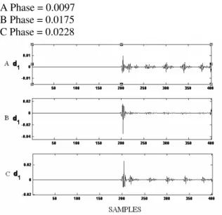
The DWT Analysis of the three phases of an inrush current when the transformer is energized at voltage closing angle 18 degree is shown in the fig. 4 . It is found that the transient spikes in detail 1 appear at the start of the inrush current, the spikes decay slowly and continues for more than ten cycles.
Maximum value of d1 coefficient for each phase during magnetizing inrush current at voltage closing angle 36 degree is shown below.
A Phase = 0.0097 B Phase = 0.0175 C Phase = 0.0228
Fig. 4: The DWT Analysis of the three phases of an inrush current at voltage closing angle 36 degree
Wavelet Transform of Internal fault current: Faults which occur between the two CT’s of the transformer are called internal faults. These currents occur due to some short circuit in the transformer windings and cause a large current to flow. The heavy current will damage the power system components, hence immediate action to isolate the faulty transformer is to be taken. The DWT analysis is shown in the graphs taking the samples in the x-axis and coefficients in the Y axis.
The DWT analysis of the three phase currents for single phase ‘C’ to G fault is shown in the fig. 5.
Fig. 5: The DWT Analysis of the three phases of C-G fault current.
It is found that the transient spikes occur immediately at the start of the fault and rapidly decay within a cycle. Maximum value of d1 coefficient for each phase during single phase ‘C’-g fault with fault resistance of 1 is shown below.
A Phase =0.0321 B Phase =0.0321
C Phase =0.0509(faulty phase)
It is very clear that the d1 coefficient of the faulty phase is greater when compared to the d1 coefficient of the inrush current. It is also found that the d1 coefficient of the faulty phase is greater than the d1 coefficients of the healthy phases. Hence, the proposed relay can easily distinguish an inrush current from the internal fault current based on the d1 coefficients and send a trip signal if the d1 coefficient is high.
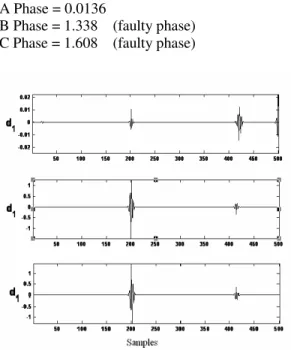
The DWT analysis of the three phase currents for double phase to ground fault (BC-G) with fault resistance of 2 is shown in the fig. 6.
458 Maximum value of d1 coefficient for each phase during double phase to ground fault ( BC-G ) with fault resistance of 2 . It is shown below.
A Phase = 0.0136
B Phase = 1.338 (faulty phase) C Phase = 1.608 (faulty phase)
Fig. 6: The DWT analysis of the three phase currents for double phase to ground fault (BC-G)
It is very clear that the d1 coefficients of the faulty phases are greater when compared to the d1 coefficient of the inrush current. It is also found that the d1 coefficients of the faulty phases are greater than the d1 coefficient of the healthy phase.
Hence, the proposed relay can easily distinguish an inrush current from the internal fault current based on the d1 coefficients and send a trip signal if the d1 coefficient is high.
Implementation of Neural Network: Neural networks have proved to be very efficient in the field of classification. In this paper, back propagation algorithm is used for classifying inrush and internal fault currents in the transformer. The choice of number of hidden layers and the number of neurons in each layer is one of the most critical problems in the construction of neural architecture. ANN with too many neurons will take long training time while ANN with too few neurons may prevent the training process to converge.
Several networks by varying the number of hidden layers and the number of neurons were trained and tested. A sample of the test conducted is shown in the table 1.
Table I: Test results for designing ANN architecture
ANN Size Error
5 / 1 0.1137
12/1 0.0400
20/1 0.0489
10/20/1 0.00419
20/10/1 0.02013
The neural network with less number of neurons takes less training time but the error is high. The neural network with two hidden layers with ten neurons in the first layer and 20 neurons in the second layer was found to give good performance with less error. Fig. 7 shows the architecture of ANN designed for classification on inrush currents and internal fault currents.
Fig. 7: Architecture of the proposed WNN
The ANN has three input neurons one for each phase of three phase differential current. The fundamental frequency of the differential current is 50Hz. Time period of a cycle is 20ms. Time period of 1/8th of a cycle is 2.5ms. Samples in 1/8th of a cycle are only given as input data for training. There are 5 coefficients in 1/8th of a cycle. The first 5 coefficients after the occurrence of a fault or inrush are given as input for training. The input data given to ANN has been reduced to a great extent. The data reduction contributes a significant role in the reduction of tripping time. It has one output neuron to classify whether it a fault or inrush current. The target output is assigned 1 for internal fault currents and 0 for inrush currents during training. Back propagation algorithm is used for training. Tansigmoid function is chosen to be the transfer function of each node. Total iteration is set to 3000. Error goal is set to 0.001. The learning rate is set to 0.7.
cases are used for training and 20 cases for testing both fault and inrush conditions.
Totally 220 cases are simulated. The three phase differential currents are obtained. Wavelet d1 coefficients are obtained for the simulated three phase differential currents for both the fault and inrush conditions and given as input for the designed neural network.
RESULTS
The designed neural network is trained for various training patterns of fault and inrush conditions. The goal of 0.001 error is achieved in 2194 iterations. The target for internal fault currents are trained to be 1 and the target for inrush currents are trained to be 0. Figure 8 shows the graph between training performance and no. of iterations to train the designed neural network.
Fig. 8: Training performance of ANN for Inrush current
Fig. 8(a): ANN output for internal fault current
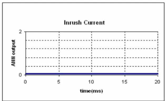
Fig. 8(b): ANN output for inrush current
The trained neural network is tested for testing patterns of various fault and inrush conditions. 1/8th of first significant cycle (5 coefficients) is used as input for the ANN. Table II shows the outputs of the ANN for various internal and inrush conditions.
Table 2: Test results of the WNN based relay
Case Target
output
ANN output
Inrush current at voltage closing angle 36 degrees.
0 0 0 0 0
0.0001 0.0001 0.0001 0.0411 0.0094
Inrush current at voltage closing angle 18 degrees.
0 0 0 0 0
0.0001 0.0020 0.0007 0.0095 0.0085
Phase C-G fault With fault resistance of 3.5
1 1 1 1 1
1.0000 1.0000 1.0000 1.0000 1.0000
Double phase AB-G fault with fault resistance 2.5
1 1 1 1 1
1.0000 1.0000 0.9998 1.0000 1.0000
Three phase ABC-G fault with fault resistance 5.5
1 1 1 1 1
460 The target output is assigned 1 for internal fault currents and 0 for inrush currents during training. The output of the ANN is very close to 0 for inrush currents and very close to 1 for internal currents. The designed neural network is found to accurately discriminate internal fault current and inrush currents. The input to the ANN is the 5 coefficients in the 1/8th of the first significant cycle. Therefore the ANN is able to distinguish and give the trip signal within 1/8th of the first significant cycle i.e 2.5ms from the switching instant. The output of wavelet and ANN based relay for internal faults and inrush currents are shown in the fig, 8(a) and 8(b) respectively.
The wavelet combined neural network has reduced the input data and tripping time of the relay.
CONCLUSION
The results clearly show that the proposed Wavelet combined neural network relay accurately distinguishes internal fault and magnetizing inrush currents in three phase transformers. The WNN effectively distinguishes and gives trip signal within 1/8th of cycle which is considered to be very fast. The relay also provides high sensitivity for internal fault currents and high stability for inrush currents.
REFERENCES
1. M.A. Rahman and B.Jeyasurya, 1998. A state-of-the-art review of transformer protection algorithms.
IEEE Trans. Power Delivery, vol. 3, no. 2, pp. 534–544.
2. Liu, P.Malik, O.P., Chen, D. and Hope, G.S., 1989. Study of Non-Operation for Internal Faults of Second-Harmonic Restraint Differential Protection of Power Transformers. Transactions of the Engineering and Operating Division of the Canadian Electrical Association, Vol. 28, Part 3, 1989, pp1-23.
3. T.S.Sidhu and M.S.Sachdev, 1992. On line identification of magnetizing inrush and internal faults in three phase transformers. IEEE Trans. Power Del., vol. 7, no. 4, pp. 1885–1890.
4. J.S.Thorp and A.G.Phadke, 1982. A
Microprocessor based three phase Transformer Differential Relay. IEEE Transaction on Power apparatus and Systems, vol.PAS-101,no. 2,Feb. pp.426-432.
5. Wiszniewski A. and Kasztenny B., 1995. A Multicriteria Transformer Differential Relay based on fuzzy logic. IEEE Trans. On Power Delivery, Vol.10, N0.4, pp. 1786-92.
6. Kasztenny B.Rosolowski E., Saha M.M. and Hillstrom B., 1996. A self-organizing fuzzy logic based protective relay - an application to power transformer protection. IEEE PES'96 Summer Meeting in Denver, paper 96-SM-386-3-PWRD. 7. M.Nagpal, M.S.Sachdev, Kao Ning, and
L.M.Wedephol, 1995. Using a neural network for transformer protection. IEEE Proc. Oh EMPD Int. conference, Nov., vol. 2,pp. 674-679.
8. M.R. Zaman, and M.A. Rahman, 1998.
Experimental testing of the artificial neural network based protection of power transformers.
IEEE Trans .On Power Delivery, April, vol. 13, no. 2, pp. 510–517.
9. Okan Ozgonenel, Guven Onbilgin and cagri kocaman, 2004. Wavelet based transformer protection. IEEE Melecon, May 12-15, Dubrovnik, Croalia.
10. S.Sudha and Dr.A.Ebenezer Jeyakumar 2007. Wavelet Based Relaying For Power Transformer Protection. Gests International Transaction on computer Science and Engineering. March, vol. 38, No. 1.
11. P.L. Mao and R.K. Aggarawal, 2001. A Novel Approach to the Classification of the Transient phenomena in Power Transformers Using Combined Wavelet Transform and Neural Network. IEEE Transactions on Power Delivery, Oct., Vol.16, No.4, pp.655-660.
12. Okan Ozgonenel, 2005. Wavelet based ANN approach for transformer protection. International journal of computational intelligence, vol. 2 No. 3. 13. Jawad Faiz and S.Lotfi-Fard, 2006. A Novel