Power Allocation with Random Removal Scheme in
Cognitive Radio System
Deepti Kakkar, Arun khosla and Moin Uddin
Abstract--Wireless communication services have been increasing rapidly and this progress has caused a shortage in frequency resources. Cognitive radio technology is expected to enable frequency resources to be used more efficiently. This paper will focus on the co-existence between a secondary user and a primary user in order to increase the spectrum utilization by secondary users. We develop an approach to allow the unlicensed user to operate in the presence of the licensed user. Therefore, in order to guarantee the minimum harmful interference to primary users and meeting the Quality of Service (QoS) requirements of secondary users, the transmit power of the cognitive radio is controlled. We focus on the implementation of different power control techniques for Cognitive Radio Networks and simulated results performed using MATLAB, demonstrate the comparative effectiveness of these power control techniques.
Keywords: Cognitive Radio, Underlay System, Power Allocation, Different Power Control Approaches.
I. INTRODUCTION
Cognitive Radios have emerged as a solution to the problem of spectrum scarcity for wireless applications. It is a key technology that will enable flexible, efficient and reliable spectrum use by adapting the radio’s operating characteristics to the real-time conditions of the environment. This new communication paradigm can dramatically enhance spectrum efficiency, and is also referred to as the neXt Generation (XG) network. We consider a general scenario in which, the CR-enabled Secondary Users (SUs) are able to sense the available spectrum and share with Primary Users (PUs) efficiently. On the other hand, the spectrum sharing between PUs and SUs brings on a significant challenge. The SUs dynamic access may result in serious interferences to PUs. In this scenario, the Cell consists of one BS, several SUs and PUs. SUs can be admitted to the BS only if the interferences to PUs are no higher than the predefined thresholds. At the same time, SUs should adapt their transmission power in order to satisfy the Quality of Service (QoS) demands. We define a secondary spectrum utilization factor which will decide that which SU can access the licensed spectrum firstly without providing significant interference to the PUs.
Manuscript received March 06, 2011; revised March 30, 2011.) Deepti Kakkar is Assistant Professor with the National Institute of engineering and Technology, Department of Electronics and Communication Engineering Jalandhar - 144 011, Punjab, India. Tel (O): 91 181 2690 301, 2690 453 Extension 2610, Mob: +919815753334. (e-mail: [email protected])
Arun khosla is Associate Professor & Head in the Department of Electronics and Communication Engineering, Dr B R Ambedkar National Institute of Technology, Jalandhar -144011, Punjab, India. Tel (O): 91 181 2690 301, 2690 453 Extension 2601, Mob: +91 98880 68332. (email: [email protected])
Moin Uddin is Pro Vice-Chancellor in Delhi Technological University, Delhi, INDIA. Tel (O):0112782284,Fax(O):01127871023,Mob :9810553516. (email: [email protected])
In this paper, we have the following contributions which indicate the major difference from the previous studies. Firstly, we formulate an optimization problem to maximize the secondary spectrum utilization by SUs subjected to the interference constraints on PUs and QoS requirements of SUs. Secondly, we propose a Power Control scheme to solve the formulated problem. Thirdly, simulation is presented to demonstrate the interaction between the secondary spectrum utilization and the number of PUs and the number of SUs. The results also show that proposed scheme can obtain much higher secondary spectrum utilization than other two schemes.
The rest of paper is organised as follows: Section II gives an overview of cognitive radios. We introduce the system model and formulate the optimization problem in section III. Section IV describes proposed method of power allocation and other two methods in underlay cognitive radio system. Section V will discuss the results. In the last section the conclusions are drawn.
II. AN OVERVIEW OF COGNITIVE RADIO
The term Cognitive Radio was firstly described by Joseph Mitola [1]. From his description we can define the Cognitive Radio as a radio capable of analyzing the environment (as channels and users), learning and predicting the most suitable and efficient way of using the available spectrum and adapting all of its operation parameters [1-3]. The main reason for introducing the cognitive radio is the inefficient use of the radio resources and particularly the spectrum. Spectrum sensing is an essential functionality of CRs. The aim of spectrum sensing is to find opportunities for agile use of spectrum. In general, there are two sensing modes, reactive sensing and proactive sensing, depending on the way to initiate the sensing. Reactive sensing:The sensing is initiated only when the user has data to send, thus it is called on-demand sensing. If no usable channel was found, the user will wait for a predefined time and then restart sensingagain until the user send all data that he was trying to send. Proactive sensing:The sensing is done periodically even when the user is not intending to send any data. The time between the sensing iteration is called the sensing period. Some of the key features that are typically associated with CR include [5]:
•Maintains awareness of surrounding environment and internal state
• Adaptsto its environment to meet requirements and goals
• Reasonson observations to adjust adaptation goals
•Learns from previous experiences to recognize conditions and enable faster reaction times
• Anticipatesevents in support of future decisions
Generally, spectrum sensing techniques fall into three categories: energy detection [6], coherent detection [7] and cyclo-stationary feature detection [8]. If the secondary user has limited information on the primary signals (e.g., only the local noise power is known), then the energy detector is optimal [9]. When certain primary signal features are known to the CRs (such as pilots, preambles, or synchronization messages), the optimal detector usually applies the matched filter structure to maximize the probability of detection. On the other hand, cyclo-stationary feature detectors differentiate the primary signal energy from the local noise energy by exploiting certain periodicity exhibited by the mean and autocorrelation of a particular modulated signal. Cognitive radio can either operate in an overlay or underlay fashion. In overlay fashion, unlicensed users (also known as secondary users) equipped with cognitive radios opportunistically operate in fallow licensed spectrum bands without causing interference to licensed or primary users [10] and underlay cognitive radio system in which the secondary users can make use of the allowance of the primary users’ SINR constraints and operate on the same spectrum band as the primary signals [11].
III. SYSTEM MODEL AND PROBLEM FORMULATION A. System Model:
We consider a centralized cognitive radio network. Within the cell, there is a Base Station (BS) and provides services to the set of primary users, Ns and secondary users, Ns. The BS station is providing services to the fixed cognitive radios (CRs) by opportunistically making use of available spectrum. A sample deployment of the network is shown in Figure 1.
Figure1. The Cognitive Radio Network
The SUs can access the radio frequency spectrum simultaneously. This system model is making the scenario in which all PUs are staying in receiving mode, and SUs are trying to transmit data in the uplink to the BS. Hence PUs will receive the interference from SUs. An assumption is made that the channel usage pattern of the primary users is fairly static over time so that the cognitive radio network can carry out primary user detection easily and thereby avoiding interfering with primary user operation. A free-space path loss model with the path-loss exponent of n is assumed. To facilitate further discussion; let us introduce the following notations:
N denotes the total number of CRs.
M denotes the total number of PUs.
N0 denotes the noise power spectrum density of each CR.
Without loss of generality, we assume that the interference caused by primary user’s transmissions to CRs is regarded as part of noise.
jdenotes the interference power threshold at PU j.
Pis denotes the transmission power at SU i.
ijdenotes the interference from SU i to PU j. uidenotes the utilization factor for SU i.
isb denotes the power attenuation from SU i to the BS.
isp denotes the power attenuation from SU i to the PU j.
disb denotes the distance between SU i and the BS. disp denotes the distance between SU i and the PU j.
Ri maximum data transmission rate from the SU i to the BS. γimin denotes the minimum SNR required by SU i.
Gis denotes the antenna gain of the SU i. Gjp denotes the antenna gain of the PU j. Gbdenotes the antenna gain of BS.
B. Interference Temperature Model:
The Interference Temperature Model [12], which is proposed by FCC in 2003, provides the dynamical management and allocation of the spectrum resources. It allows unlicensed radios to sense their current RF environment and transmit in licensed bands, even though their transmission does not raise the interference temperature of the frequency band over the interference temperature limit of its.
The interference temperature is defined as a measurement of the RF power generated by other emitters and noise sources, which is available at the receiving antenna and will be delivered to a receiver. In addition, it is the temperature equivalent of the RF power available at a receiving antenna per unit of bandwidth, measured in units of Kelvin. Interference temperature is calculated as follow:
(1)
where is the interference temperature with the central frequency fc and the bandwidth B. is the
average interference power in Watts (at the antenna of a receiving or measuring device) centered at the frequency fc
and covering the bandwidth B (in Hertz). k is the Boltzmann’s constant (1.38×10⁻²³ Joules per Kelvin).
For a given geographic area, the FCC would establish an interference temperature limit. This value would be the maximum threshold of the tolerable interference for a given frequency band in a particular location. Any unlicensed transmitter utilizing this band should guarantee that the transmissions added to the existing interference cannot exceed the interference temperature limit at a licensed receiver.
While SUs share the spectrum with PUs, SUs will cause interferences to the PUs. Let denotes the interference caused by SU i to PU j
(2)
admitted or not. = 1 represents that SU i is admitted, zero otherwise. refers to the transmission power at SU i. denotes the power attenuation from SU i to PU j and is given by
(3)
Where denotes the distance between SU i and the PU j. The exponent n is the path loss factor. and denotes the antenna gain of the SU i and PU j, respectively. Therefore, according to (2) and (3), the interference power caused by SU i is expressed as
(4)
C. QoS Requirement of Cognitive Radios:
According to Shannon’s channel capacity formula, the uplink maximum data transmission rate , from the SU i
to the BS, is given by
) (5)
where B is the uplink bandwidth. is the uplink SNR of SU
i measured at the BS. In the network, different SUs may require different traffic demands and data transmissionrate. Let denote the minimum required SNR for SU i. Therefore, based on (5), we can obtain the required SNR as
(6)
According to the definition of SNR, we can calculate the uplink SNR of an active SU i as following
(7)
where denotes the power attenuation from SU i to the BS.Similarly, we have
(8)
where stands for the antenna gain of the BS. refers to the distance from SU i to the BS.
D. Operational Requirements:
1) SNR Requirement for CRs: For reliable transmission, the SNR requirement of active SUs must be satisfied, i.e.
(9)
2) Protecting Primary Users: We require that, for each PU,
the total interference power from all opportunistic transmissions does not exceed a predefined threshold , i.e.
(10)
E. Objective:
In this paper, we are concerned in finding feasible power allocation schemes that maximize the total number of
active CRs supported. The above mentioned control objective is suitable for scenario in which CRs have the same throughput requirement, which is reflected in the same SNR constraint of . One example is the case when CRs have constant bit rate circuit switch traffic.
IV. POWER CONTROL SCHEMES
One of the most challenging problems of cognitive radio is the interference which occurs when a cognitive radio accesses a licensed band but fails to notice the presence of the licensed user (Overlay Cognitive Radio System). To address this problem, the FCC’s new spectrum policy gives permission to quantify the interference temperature and to manage the interference temperature in a radio environment. It means that the cognitive radio users can access the licensed spectrum as long as the created interference to the primary user is below a threshold (Underlay Cognitive Radio System), i.e., the Quality of Service (QoS) of the primary users is not affected. Therefore, the transmit power of the cognitive radio users is limited to guarantee the QoS of the primary user.
A. Proposed Power Control Technique:
In this section, a Power Control scheme is proposed to solve the optimization problem. Let and denote the valid set of PUs and the possible set of admitted SUs, respectively. Initially, all SUs are admitted by the BS and all PUs should be taken into account. Let denote the minimum transmission power of SU i to achieve the required minimum SNR . The minimum transmission power of SU i, transmitting towards the BS, can be calculated by (6), (8) and (9) as follows:
(11)
Transmission power of SUs, is selected equal to , for all i in the set of because if there exists any SU
i in the set , whose transmitting power, is greater than , then it will cause more interferences to any other SU j
(∀ j ∈ , j i). Because of that if SU j does not increase its transmission power; its SNR will decrease according to (7). Therefore, to keep their SNRs non-decreasing, all SU j (∀ j
∈ , j i) will increase their transmission power. On the other hand, if SUs increase the transmission power, PUs will receive more interference. Due to the constraint of interference threshold, fewer SUs can be admitted, which will result in smaller secondary utilization of the spectrum. This will be worse than the situation when each SU uses
as the transmission power.
After allocating the power to every active SU, calculate the interference power from every SU to every PU i.e. and check the condition given by (10). If
, then the total interference power received by the PU j is less than its threshold. This shows that, the assignment of transmitting power of SU i is feasible and SUs can transmit at that power. Otherwise the assignment is not feasible. Consequently, we introduce the
(12)
The SU with high spectrum utilization factor is able to access the spectrum most of the time while generating low interference to PUs. Our objective is not limited to the re-assignment of secondary user to network, but to provide minimum interference to the primary user and increase the utilization of the spectrum. In order to achieve high secondary utilization of the spectrum with guaranteed interference power on PUs, we can remove the SU with the minimal spectrum utilization factor in the next iteration. The pseudo-codes for the proposed scheme are:
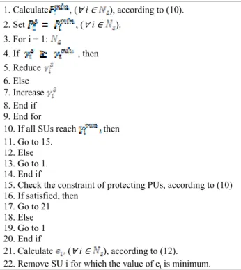
TABLE 1: PSEUDO CODES FOR THE PROPOSED SCHEME
1. Calculate , (∀ i ∈ ), according to (10).
2. Set , (∀ i ∈ ).
3. For i = 1:
4. If , then
5. Reduce
6. Else
7. Increase
8. End if 9. End for
10. If all SUs reach then
11. Go to 15. 12. Else 13. Go to 1. 14. End if
15. Check the constraint of protecting PUs, according to (10) 16. If satisfied, then
17. Go to 21 18. Else 19. Go to 1 20. End if
21. Calculate (∀ i ∈ ), according to (12).
22. Remove SU i for which the value of ei is minimum.
B. Other Power Control Techniques:
To compare the performance of proposed power control scheme, two more power control schemes, i.e. removal of unlicensed users with minimum SNR value and random removal of secondary users with any SNR value are discussed.
TABLE 2: PSEUDO CODES FOR MINIMUM SNR REMOVAL SCHEME
1. Calculate , (∀ i ∈ ), according to (11).
2. Set , (∀ i ∈ ).
3. Check the constraint of protecting PUs, according to (9) 4. If satisfied, then
5. Go to 9 6. Else 7. Go to 1 8. End if 9. For i = 1:
10. Calculate SNR value for each SU
11. If , then
12. Set
13. Remove the SU having minimum SNR value 14. End if
15. End for
Removal of Unlicensed users with minimum SNR value technique is slight different from our proposed technique. In This technique set of SUswill be updated by removing the SU with the minimal SINR in each iteration. The pseudo-codes for the scheme are given in table 2
On the other hand, the pseudo codes for random removal of secondary users having any SNR value technique. In This technique, the set of SUswill be updated by removing the SU randomly in each iteration. The pseudo-codes for the scheme are:
TABLE 3: PSEUDO CODES FOR THE RANDOM REMOVAL SCHEME
1. Calculate , (∀ i ∈ ), according to (10).
2. Set , (∀ i ∈ ).
3. Check the constraint of protecting PUs, according to (9) 4. If satisfied, then
5. Go to 9 6. Else 7. Go to 1 8. End if 9. For i = 1:
10. Select randomly any SU
11. Remove the selected SU having any SNR value 12. End for
V. RESULTS AND ANALYSES
Simulated outcomes are examined in this section to demonstrate the comparative performance of the power control schemes. The performance of proposed power control technique is compared with other two power control technique, i.e. removal of unlicensed users having minimum SNR value and random removal of secondary users having any SNR value.
In the computer simulation, we consider a cell area of radius 1000m and the Base Station (BS) is placed at the centre of the cell. The minimum distance from the BS to any SUs or PUs is set as 100m. The distance between PUs (or SUs) and the BS are arbitrarily taken inside the range from 100m to 1000m. The parameters used in the various calculations to find out desired results aretabulated below:
TABLE 4: PARAMETERS
Parameters Range Angles from any SUs (or PUs) to the BS [0,2 ]
Bandwidth B 5 MHz
DTR demand required by every SU {8,32,128} kbps
Path Fading Factor, n 4
Power Gain of Antenna situated at SU 1 Power Gain of Antenna situated at PU 1
The use of licensed spectrum made by SU i (i∈Ns),
ui, depends upon the DTR. The SU with higher DTR will use more frequency spectrums and hence provides higher spectrum utilization of the channel. Without loss of generality and for the sake of illustration, ui = 1 for DTR 8 kbps, ui = 4 for DTR 32 kbps and ui = 16 for DTR 128 kbps. The comparison of proposed scheme with other schemes is evaluated in terms of the key parameters, i.e. the number of PUs and the number of SUs.
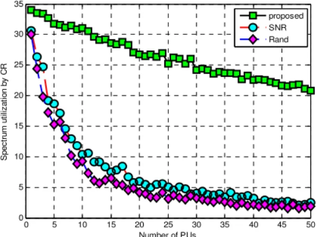
A. Effect of the number of PUs:
In this case, there are 50 SUs in the Cell. For each different number of PUs, we compute the average radio frequency spectrum utilization efficiency of 100 running times. In each running time, the location of PUs and SUs and DTR demands are randomly generated, and the interference power threshold of every PU is randomly selected from [10 -10
, 10-9] W.
Figure 1shows that as the number of PUs increases by three different power control schemes, the electromagnetic spectrum utilization by SU goes down. More PUs in the cell will result in more stringent interference constraints. The large number of PUs permits to fewer SUs to access the spectrum and hence lower utilization of spectrum by Secondary users. The third power control scheme achieves the lowest secondary spectrum utilization, since it does not consider the interference constraints and may remove SUs having high SNR values. As shown in the figure, the spectrum can be utilized more efficiently by SU by employing second power control scheme than by using third scheme since second method iteratively removes the SU with the minimal SNR, which gives maximum interference to the system.
0 5 10 15 20 25 30 35 40 45 50
0 5 10 15 20 25 30 35
Number of PUs
S
pe
c
tr
um
ut
ili
z
at
ion by
C
R
proposed SNR Rand
Figure 1: Spectrum Utilization by CR Vs Number of Primary Users
From figure it is clear that with the proposed power control technique, the secondary users can access spectrum more efficiently than other two techniques and also providing the required QoS to the both primary users and secondary users.
B. Effect of the number of SUs:
In this case, there are 6 PUs in the Cell. For each different number of SUs, we compute the average radio frequency spectrum utilization efficiency of 100 running times. In each running time, the location of PUs and SUs and DTR demands are randomly generated, and the interference
power threshold of every PU is randomly chosen from [10-10, 10-9] W.
0 5 10 15 20 25 30 35 40 45 50
0 5 10 15 20 25 30 35
Number of SUs
Sp
e
c
tr
u
m
u
tiliz
a
tio
n
b
y
C
R
proposed SNR Rand
Figure 2: Spectrum Utilization by CR Vs Number of Secondary Users
Figure 2 shows that the secondary utilization of radio frequency spectrum increases as the number of SUs increases by three different schemes. When the number of SUs is less than 4, all these schemes provides the same secondary utilization of spectrum. In this situation, the number of SUs is so few that the interference power on all the PUs are too small to exceed the threshold. As the number of SUs increases, these power control schemes perform differently. Again, third technique achieves the least secondary spectrum utilization because it may remove the SUs providing low interference to the system. Second technique achieves more secondary utilization than third scheme for the system because it can keep the SUs with high SNR value. Our proposed scheme achieves the balance between the spectrum utilization and the interference as the no. of SUs increases, and can achieve the highest secondary spectrum utilization as shown in the figure.
VI. CONCLUSION
REFERENCES
[1] J. Mitola, “Cognitive Radio: an integrated agent architecure for software defined radio”, PhD Dissertation, Royal Institute of Technology (KTH), Stockholm, 2000.
[2] S. Haykin, “Cognitive radio: Brain-empowered wireless communication, IEEE Journal on Selected Areas in Communication, vol. 23, pp. 201–220, February 2005.
[3] R.W. Thomas, L.A. DaSilva, and A.B. MacKenzie, “Cognitive Networks”, Proc. IEEE International symposium, Dynamic Spectrum Access Networks (DySPAN),2005, pp.352-360.
[4] D. Cabric, S. M. Mishra, and R. Brodersen, “Implementation issues in spectrum sensing for cognitive radios,” in Proc. 38th Asilomar Conf. Signals, Systems and Computers, Pacific Grove, CA, Nov. 2004, pp. 772– 776.
[5] “IEEE 802 Tutorial: Cognitive Radio”, Scott Seidel, Raytheon, Presented at the IEEE 802 Plenary, 18 July 2005.
[6] S. M. Kay, Fundamentals of Statistical Signal Processing: Detection Theory. Englewood Cliffs, NJ: Prentice-Hall, 1998.
[7] D. Cabric, A. Tkachenko, and R. W. Brodersen, “Experimental study of spectrumsensing based on energy detection and network cooperation,” in Proc.ACM1st Int. Workshop on Technology and Policy for Accessing Spectrum (TAPAS), Aug. 2006.
[8] S. Enserink and D. Cochran, “A cyclostationary feature detector,” in Proc. 28th Asilomar Conference on Signals, Systems, and Computers,
Monterey, CA, Oct.1994, pp. 806–810.
[9] A. Sahai, N. Hoven, and R. Tandra, “Some fundamental limits on cognitive radio,” in Proc. Allerton Conf. Communication, Control, and Computing, Oct.2004, pp. 131–136.
[10] B. Wild, and K. Ramchandran,” Detecting Primary receivers for cognitive radio applications”, Proc. IEEE International symposium, Dynamic Spectrum Access Networks (DySPAN), 2005, pp.124-130. [11] T.X. Brown, and A. Sethi, “ Potential Cognitive Radio Denial-of-
Service Vulnerabilities and protection countermeasures: A Multi- Dimensional analysis and assessment”, Cognitive Radio Oriented wireless Networks and Communications (CrownCom), 2007, pp.456- 464.