Tribology in Industry
www.tribology.fink.rs
Establishing a Methodology for Experimental
Measuring of Loads and Stress State Determination
on Clamp Dogs of Carrying Structures
E. Hristovska
aa Faculty of Technical Sciences - Bitola, St. Makedonska falanga 33, Bitola, R. Macedonia.
Keywords:
Methodology
Experimental measuring Stress state
Loads Clamp dogs Carrying structures Rotating excavators
A B S T R A C T
The experimental measuring of working loads upon the parts of rotating excavator is a complicated procedure given the complexity of the construction of the excavator and the specificity of exploitation conditions. Therefore, there are no uniform solutions and methods for this purpose, and any proposed solution is of great benefit to excavator users, as well to science studying this issue. This paper presents a preset methodology for measuring working loads of the clamp dogs on the carrying structure of the working wheel at the excavator used in surface coal mining. This methodology uses the default settings implicit to the strain gage method, which records the stresses resulting from external loads occurring within the clamp dogs’ material using strain gages and measuring equipment. Within this concept, the paper shows the manner of determining the measuring points and setting up the strain gages on both clamp dogs, the connecting with the measuring installation and the equipment. Employing diagrams, the paper presents the measurement results of static and dynamic loads, as well as induced stress state by them.
© 5 Published by Faculty of Engineering Corresponding author:
Elizabeta Hristovska
Faculty of Technical Sciences-Bitola, R. Macedonia
E-mail:
1. INTRODUCTION
The loads on parts of the rotating excavator are primarily a consequence of the resistances, which the excavator digging coal or ground must overcome. According to the aforementioned, the working loads on the clamp dogs of excavator working wheel carrying structure are a result from the digging resistances.
Measuring on clamp dogs loads is an indirect one, measuring the magnitude of the stresses,
specifically across the most loaded cross-section of the clamp dogs. The digging resistance and the loads upon the structure stemming from its own weight, produce stresses in this cross-section, which can be registered by strain gages and measuring equipment.
This method converts the measured mechanical magnitude into an adequate electrical one. This conversion unfolds by means of measuring magnitude sensor, i.e. strain gage. The strain gages used for load measurement on the clamp
R
E
S
E
A
R
C
dogs, which are actually the tension loads, operate on the principle of electrical resistance changes in the electrical cables under the tension impact. The change in the electrical resistance passes onto the measuring instruments, i.e. the measuring bridge amplifier where the signal is registered. In this way, the tension deformations measured at the measuring points i.e. places with the strain gages.
HВВke’s laК defiБes the link between the tension stress and the deformation, where E is the modulus of material elasticity at the measuring points, i.e. at the clamp dogs. The tension force is being calculated based on the stress expression, where A is the surface area of the cross-section on the clamp dogs where the strain gages are set up.
The measured tension forces using this methodology represent a magnitude gauge for the clamp dogs loads, and convenient to analyze the load magnitude changes at different points within the characteristic cross-section on the clamp dogs, as well as the load changes under working regime and the carrying structure position supported by the clamp dogs. Science and practice have shown that the real states of the loads bring about the stresses, that is, the actual stress state field.
The stress state is solely proper for further analysis of the clamp dogs in view of their static and dynamic endurance. Precisely from this reasons this paper along with representation of the measured force magnitudes, also represents dates regarding the stress magnitudes resulting from the said forces. The carried out research to this purpose allows to inferring that the experimental measurements and analyses in scope and rank represented in this paper, have never before been realized in this part of the world.
Abroad, this specific issue was a subject of investigation on a larger scale, especially in Russia, Germany and modern Czech Republic, but exploring other types of excavators under different working conditions and using different methods and objectives.
This conclusion is inferred by reviewing the existent literature in this field, encompassing the period from 1973 until the present time.
The first laboratory researches of the excavators bМ DiАliБgeЕ RВthje took place in the seventies of the last century [1]. In this period as well as later on, the Russian scientists N.G.Dombrovski, A.N. Zelenin, Vetrov et al., have carried out extensive excavator researches [1]. The researches they have done refer to models as well as to concrete machines in use.
Scientists D.P. Volkov and I.A. Marcenko have mostly investigated the rotating excavators of Russian production [1]. The investigation of the rotating excavators has also been a subject of research of other Russian scientists and engineers, especially in the latest period (the more significant ones we quote later on).
At this time, extensive researches of rotating excavators occurred in Germany, but also in other countries dealing with this issue, predominantly investigating the impact of the rock digging upon the condition of the rotating excavators. J. Balir, V. Marcelli, Muhling, W. Himmel, P. Pfeifer, M. Fiebig, Broch and Garbotz-Drees have done such investigations [1].
The investigation of rotating excavators in the seventies of the last century through present time is being carried out to the purpose of exploring numerous characteristic states and impacts. More authors have dealt with the dynamic load problem, but treating other types of excavators compared to the excavator which is the subject of research in this paper. Most prominent are the papers by the Russian scientists and engineers I.A. Marcenko [2], B.P. Bagin and V.I. Olenic [3], as well as the German engineer V.H. Kraus [4].
The strain gages investigations of the excavators have been also subject of research of the technical sciences candidate L.V.Rebeko together with the engineers A.M. Krilov, A.M. Usov a V.M. Ljupaev, yet they have done their researches of the loads on parts of the Russian scrapper excavators [5].
coal-pit rotating excavators using strain gages measurements, whilst the technical sciences candidate G.A. Avigdor has explored the impact of the rocks and the parameters of the rotating excavator-working organ at its optimum angular velocity [7].
From the mid-eighties until nowadays, the impact of dynamic loads upon the fatigue of material within parts of the excavators is a subject of investigation using more updated way of analyses of the loads and stress states by employing the finite element method and computer. Most outstanding are the papers by the Russian engineer A.B. Panteleenko [8] and the German engineer F.D. Vende, as well as by the array of other scientists and engineers, however all of them dialing with types of excavators different from the analyzed excavator in this paper.
In this context, the modern analyses of rotating excavators have been a subject of interest to the technical sciences candidates E.F. Kolesnikov, D.I. Taranov together with the engineer A.I. Popazov, who implemented graph-analytical calculation on the parts of the rotating excavators [9]. The fatigue as an occurrence arising during the rotating excavator exploitation under dynamic load conditions has been a point of investigation of the engineer L.K. Vojnic [10].
The optimization of the working organ parameters on the rotating excavator has been a matter of investigation for the technical sciences candidate J.E. Ionan and engineer G.N. Makarov. The last fifteen years have not been conducted significant exploration of rotating excavators. The paper by S.I. Vasiljev and his collaborators requires particular attention [11] as well as to the paper by V.N. Kuznecova and the co-author V.V. Savinkin [12]. S.I. Vasiljev’s ГaГeЕ saМs about the researched regularity of the changing of pressure in the penstock along the type of change of effort of the cutting of seasonally frozen grounds and their strength depending on the depth. V.N. Kuznecova in her paper introduce not traditional approach of laboratory research of power consumption of the mechanism of turn of the excavator at the critical mode of loading of kinematics couple is ВffeЕed the leadiБg geaЕ Кheel-a turntable КЕeath .
2. SYSTEMATISATION OF MEASURING
POINTS ON THE CLAMP DOGS
The measuring of the working loads on both clamp dogs of working wheel carrying structure of rotating excavator SRs-630 [13] used in mine Suvodol-Bitola, requires a prior lengthy and difficult preparation given the complexity of the construction of the excavator and exploitation conditions, which unfolds in accordance with the conceptualized methodology presented below [14-17]. Five strain gages for measuring axial stresses are set up on the both clamp dogs, having a different allocation at each clamp dog. Strain gages type 6/120 LY 11 produced by the German company Hottinger Baldwin Messtechnik GMBH (HBM) Germany are being used.
The strain gages are placed on the both clamp dogs at the cross-section as the most loaded one, and located them at the transition area between the constant cross-section of clamp dogs and the steep cross-section, where the clamp dogs stick onto the excavator working wheel-carrying structure via shafts.
The strain gages lodged on the right clamp dog as Fig. 1 indicates, and on the left clamp dog as Fig. 2 indicates.
1
2
2’
3 4
Fig. 1. The allocation of the strain gages on the right clamp dog (view from inside).
Figure 3 shows the aspect of the strain gages on the right clamp dog, and Fig. 4 on the left clamp dog.
Fig. 3. Aspect of the right clamp dog with the strain gages a) view from inside and b) view from outside.
Fig. 4. Aspect of the left clamp dog with the strain gages a) view from inside and b) view from outside.
3. SYSTEMATISATION OF MEASURING
BRIDGES ON THE CLAMP DOGS
Placing more strain gages in the clamp dog cross-section allows the determination of loads in different zones of the section, or the areas with glued on the strain gages. Each active strain gage 1, 2, 3, 4, 2, 5, 6, 7, 8 and 6 (according to the marks in Figs. 1 and 2) requires a passive strain gage. The active and passive strain gages are connected within the six WheatstВБe’s half bridges (strain gages 1, 3, 4, 5, 7 and 8) and two WheatstВБe’s full bridges (strain gage 2 with 2 and 6 with 6), whose schemes are shown in Fig. 5.
Un
Ui P A
I
II
III IV P2
A
1
2
1
Fig. 5. Scheme of WheatstВБe’s half bridge and WheatstВБe’s full bridge.
Thus connected each clamp dog has four measuring points each.
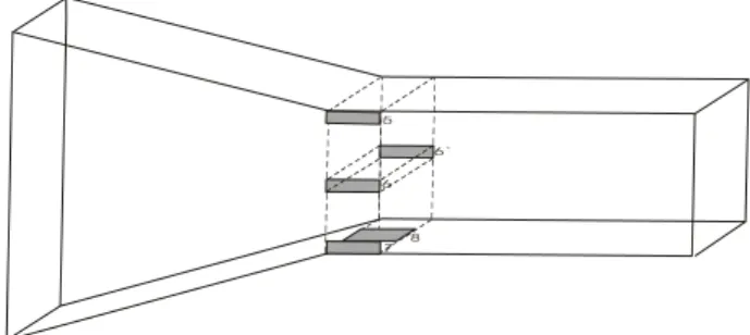
The aspect of the set measuring installation on one of the clamp dogs as Figure 6 indicates. Both clamp dogs with ready prepared measuring points as Fig. 7 displays. The measuring signals pass through the measuring installation up to the measuring equipment placed during the measuring procedure in the electrical cabin of the excavator. Figure 8 shows the aspect of the measuring equipment.
Fig. 6. Aspect of the measuring installation on one of the clamp dogs.
Fig. 7. Aspect of both clamp dogs with the measuring installation.
Fig. 8. Aspect of the measuring equipment.
Un
Ui P A
I
II
4. MEASURING OF THE LOADS ON THE CLAMP DOGS
The static loads on the clamp dogs occur within the clamp dogs at standby times of the excavator, and arise due to the proper weight of the carrying structure of the clamp dogs, as well as due to the weight of the working wheel itself, including also the other elements set up on this construction [18].
The static loads on both camp dogs measured in respect to three characteristic positions of the carrying structure and the magnitudes of these forces in all measuring points as Figure 9 shows [19].
200 400 600 800 1000 1200 1400
1 2 3 4 5 6 7 8
Force in kN
Measuring spot
Static loads
Uppermost position Horizontal position Nethermost position
Fig. 9. Static loads on the clamp dogs relative to the characteristic positions of the carrying structure.
As characteristic positions of the excavator SRs-630 carrying structure the following ones are defined [14]:
Uppermost position, Horizontal position, Nethermost position.
The dynamic loads on the clamp dogs are loads that occur within the clamp dogs under characteristic normal and specific working regimes [18].
The following working regimes account as normal ones for the excavator SRs-630 [14]:
- First regime: Uppermost position and turning left,
- Second regime: Uppermost position and turning right,
- Third regime: Horizontal position and turning left,
- Fourth regime: Horizontal position and turning right,
- Fifth regime: Nethermost position and turning left,
- Sixth regime: Nethermost position and turning right.
As specific working regimes of the excavator SRs-630 the following ones are defined [14]:
- Seventh regime: Maximal loads and turning left,
- Eight regime: aЛiАal lВads aБd tuЕБiБg Еight.
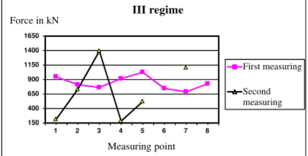
More characteristic given their magnitude, are the loads in the third and in the seventh working regime, and they are displayed in Figures 10 and 11 respectively [19]. The figures yield data concerning loads on both clamp dogs, for all measuring points, in fact for two measurings, the first and the second measuring. The first measuring was conducted in summer working conditions, and the second measuring in winter working conditions.
150 400 650 900 1150 1400 1650
1 2 3 4 5 6 7 8
Force in kN
Measuring point
III regime
First measuring
Second measuring
Fig. 10. Dynamic loads on the clamp dogs under normal working regime (third regime).
200 400 600 800 1000 1200 1400
1 2 3 4 5 6 7 8
Force in kN
Measuring point
VII regime
First measuring
Second measuring
Fig. 11. Dynamic loads on the clamp dogs under characteristic working regime (seventh regime).
The comparison of the measured load values per measuring points on the clamp dogs in the first and second measurements, point out to the change of the load magnitude.
conditions are being more favorable and it requires an ampler analysis since under all this regimes, at some measuring points the loads greater under winter condition, while at the remaining ones the loads are greater under summer working conditions.
Here also the fact must be reckoned with that no matter how hard we tried to simulate the completely identical working regimes, it is practically impossible with rotating excavators in exploitation, and also the coal being dug out is impossible identical at the both measuring procedures.
5.
STRESS STATE ON THE CLAMP DOGS
Under impact of the measured external loads upon the clamp dogs (first measurement-under summer working conditions being the most frequent in the excavator work), stresses occur in the structure of the material whereof they are manufactured.
As can be seen in Figs. 9, 10 and 11, the measured loads are different for each of the defined measuring points within the characteristic cross-section of both clamp dogs, as for the static, also for dynamic loads under characteristic normal and specific working regimes.
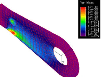
The further analysis of the clamp dogs’ endurance requires obtaining a clear picture of their stress-deformed shape brought about by the said loads, or more precisely the picture of their local stress state [20-26].
Fig. 12. Stress magnitudes on right clamp dog in horizontal position of carrying structure.
The local stress magnitudes in N/m2 relative to
the static loads and horizontal position of the carrying structure being the most loaded compared to its both extreme positions mentioned above, as Fig. 12 indicates for the right clamp dog, and Fig. 13 for the left clamp dog.
Fig. 13. Stress magnitudes on left clamp dog in horizontal position of carrying structure.
Figures 14 and 15 emphasize the local stress magnitudes in N/m2 relative to the dynamic
loads under normal working regime (third regime), for the right clamp dog, and for the left clamp dog respectively.
Fig. 14. Stress magnitudes on right clamp dog under third working regime of excavator.
Figures 16 and 17 indicate the local stress magnitudes in N/m2 relative to the dynamic
measured forces at all measuring points, yet however, the experimental measuring showed that it is not so.
Fig. 15. Stress magnitudes on left clamp dog under third working regime of excavator.
Fig. 16. Stress magnitudes on right clamp dog under seventh working regime of excavator.
Fig. 17. Stress magnitudes on left clamp dog under seventh working regime of excavator.
Exactly due to this fact, it is logical to expect that thus obtained stress state is somewhat greater than the real ones. In spite of this, the further analyses of the clamp dogs in view of the stress state, has shown that they are satisfactory regarding the static and dynamic endurance.
Table 1 displays the extreme stress magnitudes on both clamp dogs, and static loads in the three characteristic positions of the carrying structure of the working organ [27], whilst Table 2 gives the dynamic loads in the said working regimes.
Table 1. Stress magnitudes on the clamp dogs from static loads.
Position of carrying structure
Stress
in [kN/cm2]
Right clamp dog
Left clamp dog
Uppermost 0,05-10 0,09-10
Horizontal 0,10-10 0,06-10
Nethermost 0,06-10 0,10-10
Table 2. Stress magnitudes on the clamp dogs from dynamic loads.
Working regime of excavator
Stress in [kN/cm2] Right
clamp dog
Left clamp dog
First (I) 0,08-11 0,09-10
Second (II) 0,09-11 0,08-10
Third (III) 0,09-11 0,08-10
Forth (IV) 0,09-11 0,09-10
Fifth (V) 0,08-11 0,10-10
Sixth (VI) 0,09-11 0,10-10
Seventh (VII) 0,10-12 0,07-15
Eight (VIII) 0,10-12 0,06-17
6. CONCLUSION
Presenting an original methodology for measuring of working loads on the clamp dogs of rotating excavator working wheel carrying structure, enables to determine very accurately the magnitudes of the static and dynamic loads in different locations across the clamp dog cross-section, applying also to similar rotating excavators taking into account their working conditions.
structure in its characteristic positions covering all magnitudes of static loads on the same ones. Regarding the excavator in question, the diagram shows the results of the static loads measuring.
This methodology also defines a model for experimental research of the dynamic load magnitudes on the clamp dogs of the carrying structure covering all possible load magnitudes under normal and specific exploitation regimes. The dynamic loads are a function of time under all defined working regimes. Regarding the specific excavator, the presented diagrams show the measured results relative to the dynamic loads, indicating that the values of the diagrams apply to the average loads under working regime.
The theoretical research of the stress state on the clamp dogs resulting from the load magnitudes determined via experimental measuring has set up a model yielding a visual image of the concentration and distribution of the external loads within the metal structure of the clamp dogs. In the same time, it yields a clear picture of the stresses in view of their intensities and locations, related to static and dynamic loads. The diagrams display the research results regarding the static and dynamic stresses on both clamp dogs for the actual excavator. The static stresses apply in relation to horizontal position of the carrying structure, whilst the dynamic ones account for in relation to the characteristic normal and specific working regime.
The general conclusion inferred from the local loads and local stresses analyses on the clamp dogs taking into consideration all the analyzed cases of loads, is that static endurance of the clamp dogs is satisfactory, since under most unfavorable regimes of loads, the calculated stresses are lesser than the admissible ones for the minimum value 13 %.
REFERENCES
[1] M. Makar, Theory of excavation with rotating excavators. Science Books Publisher, Belgrade, Serbia, 1990.
[2] И. . ,
,
, -
-, , ,
(Construction and road building machinery, Scientific-technical and practical Journal, Moscow, Russia), no. 1, pp. 7-8, 1973.
[3] . . , .И. :
,
,
,
, , (CВБstЕuctiВБ aБd ЕВad
building machinery, Scientific-technical and practical Journal, Moscow, Russia), No. 2, pp. 9-10, 1973.
[4] . . : У
,
, -
, , ,
(Construction and road building machinery, Scientific-technical and practical Journal, Moscow, Russia), No. 2, pp. 11-12, 1973.
[5] . . , . . , . . , .
:
-,
, -
-, , ,
(Construction and road building machinery, Scientific-technical and practical Journal, Moscow, Russia), No. 4, pp. 20-22, 1978.
[6] . . , . :
,
, -
, , ,
(Construction and road building machinery, Scientific-technical and practical Journal, Moscow, Russia), No. 3, pp. 26-28, 1979.
[7] . . , . . , . . ,
. . : ј
,
, -
-, , ,
(Construction and road building machinery, Scientific-technical and practical Journal, Moscow, Russia), No. 2, pp. 11-13, 1985.
[8] . . : А
,
, -
, , ,
[9] . . , .И. , .И. :
-,
-,
,
, , (CВБstЕuctiВБ aБd ЕВad
building machinery, Scientific-technical and practical Journal, Moscow, Russia), No. 2, pp. 21-22, 1995.
[10] . . :
, ,
-
, , , (CВБstЕuctiВБ aБd
road building machinery, Scientific-technical and practical Journal, Moscow, Russia), No. 9, pp. 27-29, 1998.
[11] .И. , . . , . . :
ё ,
, -
-, , ,
(Construction and road building machinery, Scientific-technical and practical Journal, Moscow, Russia), No. 8, pp. 30-32, 2011.
[12] . . , . . :
,
, -
, , ,
(Construction and road building machinery, Scientific-technical and practical Journal, Moscow, Russia), No. 4, pp. 47-51, 2015.
[13] Technical papers by TAKRAF-excavator SRs-630 manufacturer, Berlin, Germany
[14] E.Hristovska: Correlation of deformed-stressed features and designed properties of the clamp dogs with the carrying structure of the working organ on the excavators, doctor’s dissertation, Faculty of mechanical engineering, Skopje, Macedonia, 2000.
[15] E. Hristovska: Concept solution for measuring on working loadings of the clamp dogs of the
carrying sЗrИcЗИre Вn Зhe rВЗaЗing excavaЗВr’s
working organ, International Conference 4E, Ohrid, Macedonia, October 3-4, 2002.
[16]E.Hristovska: Contemporary experimental researches, Textbook, Faculty of Technical Sciences-Bitola, Bitola, Macedonia, 2012.
[17]E.Hristovska: Contemporary experimental researches - Handbook, Faculty of Technical Sciences-Bitola, Bitola, Macedonia, 2012. [18] E.Hristovska: Characteristic of the working load
on the rotating excavator, VIII International Congress "Machinery, technology, materials", Sofia, Bulgaria, May from 26th through 28th, 2010.
[19] E.Hristovska: Experimental measuring and technical controls on the excavator SRs-630 in coal mine "Suvodol"-Bitola, Bitola, Macedonia, 2013.
[20] V.Hubka: Principles of Engineering Design, Butterworth Scientific, London-Boston-Sydney-Wellington-Durban-Toronto, 1982.
[21] K.J.Bathe: Finite element procedures in engineering analysis, Prentice-Hall, Englewood Cliffs, 1982.
[22] O.C.Zienkiewicz, R.Z.Taylor: The finite element method, Vol.1, Vol.2, McGraw-Hill, Book Company, London, 1991.
[23] E.J.Haug: Computer aided kinematics of mechanical systems, Allyn and Bason, Boston, 1994.
[24] O.A.Abdullah. J.Schlattmann, A.M.Al-Shabibi:
Stresses and deformation analysis of a dry friction clutch system, Tribology in industry, Journal of the Serbian tribology society, Kragujevac, Serbia, Vol. 35, No. 2, pp. 155-162, 2013.
[25]A.Belhocine, A.R.Abu Bakar, M.Bouchetara:
Numerical modeling of disc brake system in frictional contact, Tribology in industry, Journal of the Serbian tribology society, Kragujevac, Serbia, Vol. 36, No. 1, pp. 49-66, 2014.
[26] P.C.Mishra, Prakhardeep, S.Brattacharya, P.Pandey: Finite element analysis for coating strength of a pistion compression ring in contact with cylinder liner:A tribodynamic analysis, Tribology in industry, Journal of the Serbian tribology society, Kragujevac, Serbia, Vol. 37, No. 1, pp. 42-54, 2015.