The Brazilian standards of structures in ire prescribe minimum dimensions for the ribbed slabs to ensure ire resistance. However, a new composite ribbed slab is not covered by any of the Brazilian standards in ire. The objective of this work is to present unpublished results from numerical and thermal analyses for this type of slab. Ribbed slabs illed with cell concrete blocks, ceramic bricks and EPS supported by cimenti -tious board were studied. The constructive element is considerate as thermal insulation if it has the capacity to prevent the occurrence, on the face non exposed to ire, temperature increments greater than 140 °C on the average or greater than 180 ºC at any point. The support function was determined limiting the temperature of the beams and slabs rebars to 500 ºC. The analyses were carried out with the ATERM and Super Tempcalc, software for two-dimensional thermal analysis by means of the inite element method. As a result, tables will be presented that link the ire resistance required time to slab dimensions and position of rebar. Prior to use in designing these results must be conirmed by experimental analysis, which is already being provided.
Keywords: ire, thermal analysis, ribbed slabs, wafled slabs, composite slabs.
As normas brasileiras de estruturas em situação de incêndio fornecem dimensões mínimas para as lajes nervuradas para assegurar as fun-ções corta fogo e de estabilidade estrutural. Porém, uma nova laje mista nervurada lançada no mercado brasileiro não é coberta por qualquer das normas brasileiras para a situação de incêndio. O objetivo deste trabalho é apresentar resultados inéditos, frutos de análises numéricas
Projeto de lajes mistas nervuradas de concreto
em incêndio
I. PIerIn a [email protected]
V. P. SIlVa a [email protected]
abstract
1. Introduction
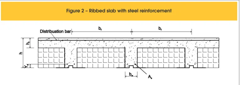
ABNT NBR 14323:2013 Brazilian standard [1] presents recommen-dations for steel and concrete composite slabs in a ire situation. ABNT NBR 6118:2007 [2] deines the ribbed slabs and prescribes minimum dimensions for the rib section to waive the veriication of lange bending. ABNT NBR 15200:2012 [3] provides minimum dimensions, by means of tables, to ensure ire resistance. A new kind of steel and concrete composite slab has been released in the market. It is a ribbed slab, manufactured by Tuper, the steel formwork (Figure 1) of which is placed at the base of the rib (Figure 2), working as a formwork and a bottom reinforcement.
Due to the characteristics of this ribbed composite slab, none of the aforementioned standards covers its design in ire situation. This work aims to investigate the behavior of these ribbed slabs at high temperatures, in order to analyze their thermal insulation, ac -cording to the procedure recommended by ABNT NBR 5628:2001 [4] and a ire resistance, based on the 500 ºC limit temperature in the reinforcement [5], [6].
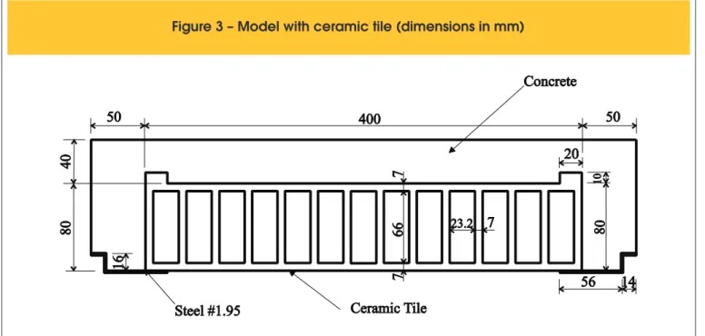
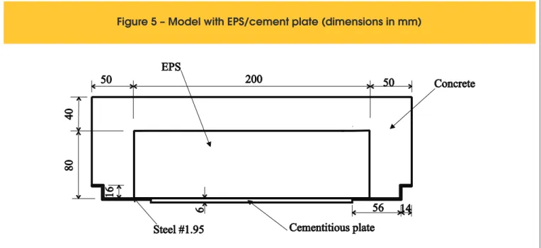
The slabs under study are illed with either ceramic tiles (Figure 3), cellular concrete blocks (Figure 4) or EPS on cementitious plates (Figure 5). This study assumes the perfect contact between the iller and the rib wall; hence, all the results should be experimen-tally conirmed. The advantage of performing a numerical analysis is that the behavior of a large number of alternatives can be previ-ously foreseen, lowering the waste with experimental tests.
2. Parameters adopted for the thermal
analysis of slabs
2.1 Thermal action
The ire model used in the analysis was the standard ire (ISO-ire) (Equation 1)). According to [4] and [7], the coeficient of heat trans -fer by convection, α
c, was taken equal to 25 W/m² °C on the faces
heated directly by the ire and the resulting emissivity ε
res, 0.7.
On the face not exposed to direct heat, a combination of convec-tion and radiaconvec-tion was made, simulated by α
c = 9 W/m² °C. In
Equation 1, θ
g is the gas temperature expressed in degrees Celsius
(ºC), θ
o is the room temperature equal to 20 ºC and t is time in min.
(1)
=
+
+
g 0
q
q
345log(8t 1)
2.2 Properties of materials
2.2.1 Concrete
In the thermal analysis of structures, knowledge of thermal prop -erties such as density, thermal conductivity and speciic heat is needed. These values vary with temperature and, for concrete, the formulation presented in ABNT NBR 15200:2012 [3] was adopted, and the density at room temperature was equal to 2400 kg/m3,
as recommended by ABNT NBR 6118: 2007 [2]. The humidity ad-opted was equal to 1.5% by weight.
Figure 1 – Steel reinforcement
(dimensions in mm)
2.2.2 Steel
Properties were adopted as recommended by ABNT NBR 14323:2013 [1] and also presented in [6].
2.2.3 Ceramic tile
For ceramic tiles, there is no consensus on the values to be adopted for the properties needed for thermal analysis. Table 1 shows the val -ues of the thermal properties taken from the literature. Where no tests are available, ABNT NBR 15220-2:2005 [8] indicates the properties of
the ceramic tiles at room temperature, also shown in Table 1. The thermal conductivity of the regular concrete decreases with temperature; thus, if it is supposed that the same occurs with the ceramic tile, the conductivity value at room temperature can be con-sidered in favor of safety. Therefore, the highest thermal conductivity (1.05 W/m °C) and the lowest capacitance (density × speciic heat = 1000 kg/m3 × 835 J/kg ºC= 835000 J/m3 ºC) will be used.
2.2.4 Cellular concrete block
Also, for cellular concrete blocks, there is no consensus on the
Figure 3 – Model with ceramic tile (dimensions in mm)
values to be adopted for their properties in thermal analysis. Table 2 shows the physical and thermal properties provided by some manufacturers and by the literature.
The thermal conductivity of the regular concrete de-creases with temperature; hence, if it is supposed that the same occurs with the cellular concrete, the conduc-tivity value at room temperature can be considered in favor of safety. Therefore, the highest thermal conductiv-ity (0.3 W/m °C) and the lowest capacitance (densconductiv-ity × specific heat = 300 kg/m3 × 850 J/kg ºC= 255000 J/m3
ºC) will be used.
2.2.5 Cementitious plate
After extensive research on the physical and thermal properties of cement plates, few results were found, with great variability be-tween them, as shown in Table 3.
Due to the high deviation of values, a study was carried out to verify the inluence of the thermal properties on the slab tempera -ture ield.
According to the thermal properties presented in this item, seven simulations were performed, in which the properties of the ce-mentitious plates were varied, as shown in Table 4. In the sixth
Figure 5 – Model with EPS/cement plate (dimensions in mm)
Table 1 – Properties of ceramic tiles at room temperature
Source
Density (kg/m³)
Conductivity (W/mºC)
Specific heat (J/kg K)
CADORIN [9]
INCROPERA; DEWITT [10]
ABNT NBR 15220-2:2005 [8]
1600
1920
1000 – 2000
0.7
0.72
0.70 – 1.05
840
835
920
Table 2 – Properties of cellular concrete blocks at room temperature according to manufacturers
Manufacturer
Density (kg/m³)
Conductivity (W/mºC)
Specific heat (J/kg ºC)
SIPOREX [11]
CONSTRUPOR [12]
SICAL [13]
BARREIRA e FREITAS [14]
GAWIN et al [15]
ABNT NBR 15220-2:2005 [8]
300 – 650
400 – 800
430 – 500
525
400 – 600
400 – 500
0.12 – 0.15
0.28
0.097
0.30
0.115 – 0.162
0.17
1000 – 1100
1008
–
1050
simulation, thermal properties of concrete were adopted for the cementitious plate. In the seventh simulation, the presence of the cementitious plate was disregarded, i.e., the side faces of the rib and the lower face of the lange were directly exposed to ire.
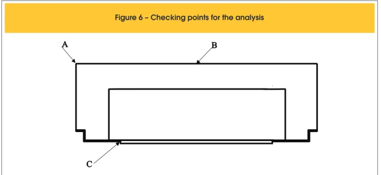
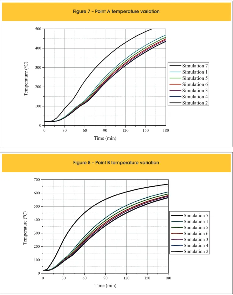
To check the inluence of the physical and thermal properties on the slab temperature ield, the temperature variation was analyzed at three points, as shown in Figure 6: point A – rib upper left corner,
point B - midpoint of the upper concrete face (lange) and point C – steel plate.
By means of Super Tempcalc thermal analysis software [19], the graphs showing the temperature variation versus ire exposure time for points A, B and C were plotted. See Figures 7 and 8. As can be seen in Figures 7 and 8, the protection provided by the cementitious plate is, despite its small thickness, not negligible when
Table 3 – Thermal properties of cement plates at room temperature,
according to manufacturers and Brazilian standard
Manufacturer
Density (kg/m³)
Conductivity (W/mºC)
Specific heat (J/kg ºC)
DUROCK – KNAUF [16]
BRASILIT [17]
ETERNIT [18]
AQUAPANEL – KNAUF [16]
ABNT NBR 15220-2:2005 [8]
1200
1700
1700
1150
1400 – 2200
2.22
0.35
0.48
0.35
0.65 – 0.95
–
–
–
–
840
Table 4 – Thermal properties of the cementitious plate analyzed
Simulation
Density (kg/m³)
Conductivity (W/mºC)
Specific heat (J/kg K)
1
2
3
4
5
6
7
1200
1700
1700
1150
1400
Concrete properties – see 2.2.1.
Absence of cementitious plate
2.22
0.35
0.48
0.35
0.95
840
840
840
840
840
Figure 7 – Point A temperature variation
0 30 60 90 120 150 180
0 100 200 300 400 500
Temperature (ºC)
Time (min)
Simulation 7
Simulation 1
Simulation 5
Simulation 6
Simulation 3
Simulation 4
Simulation 2
Figure 8 – Point B temperature variation
0 30 60 90 120 150 180
0 100 200 300 400 500 600 700
Temperature (ºC)
Time (min)
compared to simulation # 7 (no cementitious plate). On the other hand, the physical-thermal properties, simulations # 1 to 6, do not pro-foundly affect the results. For this being a numeric study and the wide variability found in the values of the plate properties, we de -cided to admit the properties of simulation # 1 in favor of safety.
3. analyses of slabs with ceramic tile
3.1 Type 12-4 slab
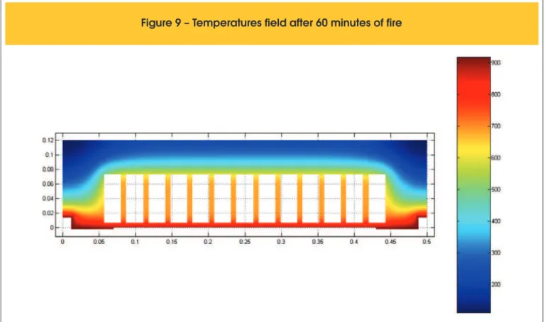
Making use of Super Tempcalc thermal analysis software [19], the thermal behavior of a ribbed concrete slab illed with ceramic tile was analyzed. Initially, the following were considered (see Figure 3): thickness of the lange equal to 4 cm, rib height from the lange equal to 8 cm, rib width equal to 10 cm, 8.0 cm high ceramic tile and 1.95 mm thick metal joist. The holes of the ce -ramic tile were supposed to be illed with air. The temperature ields were analyzed for 30, 60, 90, 120, 150 and 180 minutes of exposure to standard ire. As an example, Figures 9 and 10 show
Figure 9 – Temperatures field after 60 minutes of fire
the thermal ield and isotherms, respectively, for 60 minutes.
3.2 Other lange or lange+lining thicknesses
In order to evaluate the thermal insulation provided by the ceramic tile, the concrete lange thickness was varied from 4 to 8 cm. Since the thermal and physical properties of cement and sand mortar are similar to those of concrete, the thickness of the lange used in computer models may be substituted, in practice, by the actual
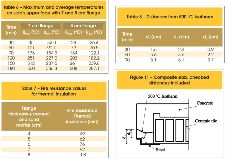
lange thickness plus one layer of cement and sand mortar. The rib height with no lange was maintained equal to 8 cm. The maximum and average temperatures obtained on the slab upper surface for 4, 5, 6, 7 and 8 cm lange thicknesses are presented in Tables 5 and 6. Table 7 was constructed from Tables 5 and 6 associating the lange thickness to the time of ire resistance for thermal insulation. Table 8 presents the distances between the lower face of the rib and the lowest (d1) and the highest (d2) points of the isotherm of
500 °C and the minimum distance between the isotherm of 500 °C and the top of the steel recess (d3), as shown in Figure 11.
Table 5 – Maximum and average temperatures on slab upper face with flange between 4 and 6 cm
Time (min)
θ
4 cm flange
(ºC)
5 cm flange
6 cm flange
max
θ
ave(ºC)
θ
max(ºC)
θ
ave(ºC)
θ
max(ºC)
θ
ave(ºC)
30
60
90
120
150
180
92
238
365
454
517
560
64
171
288
374
439
487
46
126
226
307
370
419
78.9
206.7
327.8
417.3
481.7
528.1
56.0
150.3
257.2
342.6
407.6
457.0
41.1
113.3
200.3
280.1
343.0
392.9
Table 6 – Maximum and average temperatures
on slab's upper face with 7 and 8 cm flange
Time
(min)
7 cm flange
8 cm flange
θ
max(ºC)
θ
ave(ºC)
θ
max(ºC)
θ
ave(ºC)
30
60
90
120
150
180
35
101
173
251
312
360
28
79
134
203
261
308
32.0
90.1
154.3
227.0
287.5
336.3
26.4
70.5
122.1
182.2
239.8
287.1
Table 7 – Fire resistance values
for thermal insulation
Flange
thickness + cement
and sand
mortar (cm)
Fire resistance
Thermal
insulation (min)
4
5
6
7
8
49
62
76
92
108
Table 8 – Distances from 500 ºC isotherm
Time
(min)
d (cm)
1d (cm)
2d (cm)
330
60
90
1.6
3.6
5.1
2.4
3.6
5.1
0.9
2.2
3.7
However, for structural purposes, they can be compensated by increasing the rib height. This will in no way affect the results found herein.
4. analyses of slab with cellular
concrete blocks
Time
(min)
c vertical (cm)
1c horizontal (cm)
130
60
90
2.5
3.5
5.0
2.5
5.0
5.0
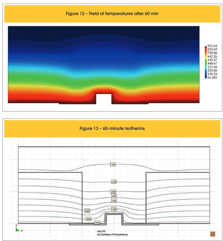
Figure 12 – Field of temperatures after 60 min
4.1 Type 12-4 slab
The analysis of the thermal behavior of ribbed concrete slab illed with cellular concrete blocks was performed. Initially, the following
Time (min)
θ
max(ºC)
θ
ave(ºC)
θ
averib
(ºC)
θ
max(ºC)
θ
ave(ºC)
θ
averib
(ºC)
θ
max(ºC)
θ
ave(ºC)
θ
averib
(ºC)
30
60
90
120
150
180
28.9
69.5
115.2
159.9
204.1
239.5
24.9
54.5
96.0
129.5
166.7
201.2
22.6
43.6
78.4
109.8
137.3
167.5
27.2
64.2
104.7
137.5
174.0
207.6
23.9
51.2
87.0
115.6
144.1
174.5
22.0
41.7
71.8
99.6
122.2
147.1
26.3
67.8
112.7
154.4
197.3
232.5
23.3
53.3
93.7
125.9
161.3
195.3
21.6
41.7
76.7
107.4
133.6
162.9
Figure 14 – Temperatures along the upper
face of a slab with 8 cm block and 4 cm flange
was considered (see Figure 3): concrete slab thickness equal to 4 cm, height of the concrete block equal to 8 cm, width of the beam equal to 10 cm and metal joist thickness equal to 1.95 mm. Due to the slab continuity, only one rib was modeled, with lange collaborat -ing width equal to 30 cm. By means of ATERM program [20], the thermal analysis of the slab was performed for 30, 60, 90, 120, 150 and 180 min. As an example, the ield of temperature and isotherms for 60 min of standard ire is presented in Figures 12 and 13.
Table 11 – Distances from 500 ºC isotherm
Time
(min)
d (cm)
1d (cm)
2d (cm)
330
60
90
120
150
180
1.4
2.8
3.8
4.6
5.2
5.8
2.4
3.3
4.1
4.8
5.3
5.9
0.6
1.6
2.4
3.1
3.8
4.4
Table 10 shows the maximum and average temperatures obtained on the upper surface for times equal to 30-180 min of exposure to ire. Average temperatures on the rib area of the upper face are also shown. The temperature variation along the upper face for periods of 30 to 180 minutes is shown in Figure 14, where the shaded area indicates the rib region. The highest temperatures are observed to occur in this region.
The ribbed slab under study with 4 cm lange and illed with 8 cm high cellular concrete blocks is found to meet the requirements of thermal insulation for ire resistance up to 120 min.
4.2 Other thicknesses of lange or lange+linings
For a better evaluation of the slab thermal insulation, a concrete lange thickness of 5 cm was adopted. Thermal analysis was re-done and it was found that, as shown in Table 10, the slab studied
Time (min)
θ
max(ºC)
θ
ave(ºC)
θ
averib
(ºC)
θ
max(ºC)
θ
ave(ºC)
θ
averib
(ºC)
θ
max(ºC)
θ
ave(ºC)
θ
averib
(ºC)
30
60
90
120
150
180
21.4
34.8
57.1
85.5
110.3
133.0
20.2
24.4
34.0
47.3
65.0
82.7
20.1
23.2
31.0
41.7
57.0
73.1
20.9
32.8
54.9
79.9
102.6
120.5
20.1
23.2
32.5
46.0
61.4
77.2
20.0
22.2
29.4
40.8
54.3
68.5
20.5
31.9
56.3
83.9
108.5
129.8
20.0
22.4
31.8
46.8
63.9
81.2
20.0
21.5
28.7
41.1
56.2
71.9
Table 13 – Distances from 500 ºC isotherm for 16-4, 20-4 and 25-4 slabs
Time (min)
d
16-4 slab
20-4 slab
25-4 slab
1
(cm)
d
1(cm)
d
1(cm)
d
2(cm)
d
2(cm)
d
2(cm)
d
3(cm)
d
3(cm)
d
3(cm)
30
60
90
120
150
180
1.4
2.9
3.9
4.8
5.5
6.0
2.3
3.3
4.1
5.0
5.5
6.0
0.6
1.5
2.4
3.3
3.9
4.4
1.4
2.9
3.9
4.8
5.6
6.2
2.3
3.3
4.1
4.9
5.6
6.2
0.6
1.5
2.4
3.3
4.0
4.6
1.4
2.9
4.0
4.8
5.6
6.2
2.3
3.3
4.1
4.9
5.6
6.2
0.6
1.5
2.5
3.2
4.0
4.6
meets the requirements for thermal insulation for ire resistance up to 150 min. Further analysis performed for a thickness of 6 cm proved that the condition of thermal insulation is met for ire resis-tance up to 180 min, as shown in Table 10.
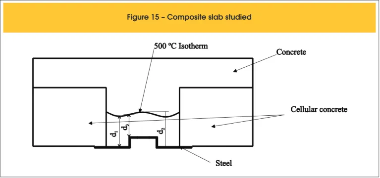
For using the simpliied method of 500 ºC limit temperature in rein-forcement, Table 11 presents the distance between the underside of the rib and the lowest point (d1) and the highest point (d2) of the 500 ºC isotherm and the minimum distance between the 500 ºC isotherm and the top of the steel recess (d3), for the slab with 4 cm lange, as shown in Figure 15.
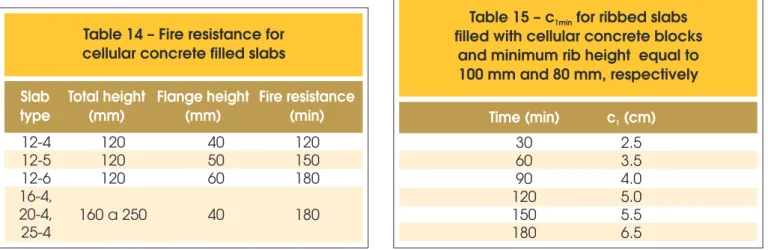
Table 13 presents the distances between the rib lower face and the lowest (d1) and highest (d2) points of the 500 ºC isotherm
as well as the minimum distance between the 500 ºC isotherm and the top of the steel recess (d3), as shown in Figure 15. Based on Table 13, one can build Table 14, related to thermal in-sulation.
By observing Table 13, the values of d1 are veriied to be quite the
same, i.e. slightly dependent on the rib height. Thus, the minimum values of c1, the distance from the reinforcement CG to the rib base
shown in Table 15 are proposed. The values were rounded due to the dificulty in obtaining millimeter precision in the ield.
It is observed that the values of c1 from Table 15, considered high
for structural purposes, can be compensated by increasing the rib height. This in no way affects the results herein.
5. analyses of slabs with ePS blocks on
a cementitious plate
5.2 Type 12-4 slab
Analyses were made on the thermal behavior of ribbed concrete slab illed with EPS block resting on cementitious plate, employing Super Tempcalc [19] software. The presence of EPS was disre-garded due to the fact that this material is quickly consumed by the heat. Initially, the following was considered (see Figure 5): thickness of the concrete slab equal to 4 cm, rib height from the lange equal to 8 cm, rib width equal to 10 cm, cementitious plate
5.2 Other lange or lange+lining thicknesses
To evaluate the thermal insulation of the slab with cementitious plate, the thickness of the concrete lange was varied from 4 to 8 cm. Having in mind that the thermal and physical properties of cement and sand mortar are similar to those of concrete, the lange thickness used in computer models can be substituted, in practice, by the lange actual thickness plus one layer of ce -ment and sand mortar. The rib height was supposed equal to 8 cm. The maximum and average temperatures on the upper surface of the slab, for thicknesses of 4, 5, 6, 7 and 8 cm, are presented in Tables 16 and 17. From Tables 16 and 17, Table 18 was constructed for thermal insulation. For information, the values standardized by ABNT NBR 15200:2012, for the case of lack of the cement plate, are provided.
Table 19 was built for use with the simpliied method of 500 °C limit temperature in the reinforcements and presents the distanc-es between the rib lower face and the lowdistanc-est (d1) and the highest
(d2) points of isotherm 500 °C and the minimum distance between 500 °C isotherm and the top of the steel recess (d3), as shown in
Figure 18.
For ire resistance higher than 120 min, the 500 °C isotherm cross -es the lange. The reinforcement should be placed in the lange and in the middle of the rib which is not feasible. Observing Table 8, Table 20 is proposed. Values were rounded in view of the dificulty in attaining millimeter precision in the ield.
The values of c1 from Table 20 are considered high but, for
Figure 17 – Isotherms after 60 minutes of fire
Table 16 – Maximum and average temperatures on the upper face of slab with 4 and 6 cm flange
Time (min)
4 cm flange
5 cm flange
6 cm flange
θ
max(ºC)
θ
ave(ºC)
θ
max(ºC)
θ
ave(ºC)
θ
max(ºC)
θ
ave(ºC)
30
60
90
120
150
180
107
276
415
507
567
608
76
200
327
418
483
529
54
143
256
342
407
456
85.4
222.5
354.0
446.9
511.1
556.3
61.1
162.9
278.5
368.4
434.9
484.1
This paper examined ribbed composite slabs illed with ceramic tiles, cellular concrete blocks and EPS on cement plate at high temperature. Conditions of thermal insulation and resistant capac-ity were analyzed.
The presence of any of the 3 types of iller studied improves the performance of the slab in ire, increasing the ire resistance time
cially, of the existence of the large space illed with heated air inside the holes of the ceramic tile and the vacuum caused by the burning of EPS, the results for thermal insulation and reinforcement po-sition presented here should be experimentally conirmed before being used in design. Similarly, tightness warranty must be ana-lyzed experimentally, since it has not been targeted in this study. The numerical procedure led to results that may be useful to guide future studies.
8. acknowledgments
The authors thank FAPESP – Fundação de Amparo à Pesquisa do Estado de São Paulo/ São Paulo Research Foundation, to CNPq – Conselho Nacional de Desenvolvimento Cientíico e Tecnológico/ Brazilian National Council of Scientiic and Technological Develop-ment and Tuper.
9. Bibliography
[01] ASSOCIAÇÃO BRASILEIRA DE NORMAS TÉCNICAS. NBR 14323: Projeto de estruturas de aço e estruturas
Table 18 – Fire resistance values
for thermal insulation
Flange
thickness +
cement
and sand
mortar (cm)
Fire
resistance
thermal
insulation
(min)
Fire
resistance
no plate
(min)
4
5
6
7
8
30
59
72
87
103
–
–
30
45
60
Table 19 – Distances from 500 ºC isotherm
Time (min)
d (cm)
1d (cm)
2d (cm)
330
60
90
1.6
3.8
5.8
2.4
3.8
5.8
0.9
2.4
4.4
Figure 18 – Composite slab. checked
distances included
Table 20 – minimum c for
1the ribbed slab studied
Time (min) c vertical (cm)
1c horizontal (cm)
130
60
90
2.5
4.0
6.0
2.5
5.0
5.0
Table 21 – Fire resistance values (min) for thermal insulation of Type 12-4 composite ribbed slabs
Flange thickness + cement
and sand mortar (cm)
Ceramic
tile
concrete block
Cellular
cement plate
EPS on
15200:2012 [3]
NBR
Time (min)
concrete
block
15200:2012
[3]
c (cm)
1c (cm)
1c vertical
1(cm)
c horizontal
1(cm)
c vertical
1(cm)
c horizontal
1(cm)
30
60
90
120
150
180
2.0
3.5
5.0
–
–
–
2.0
4.0
6.0
–
–
–
2.0
3.5
6.0
–
–
–
2.0
4.5
> 6.0
> 6.5
> 7.0
> 8.0
2.0
4.5
5.0
–
–
–
2.0
4.5
5.0
–
–
–
mistas de ao e concreto em situação de incêndio - procedi-mento. Rio de Janeiro, 2013.
[02] ASSOCIAÇÃO BRASILEIRA DE NORMAS TÉCNICAS. NBR 6118: Projeto de estruturas de concreto - procedimen -to. Rio de Janeiro, 2007.
[03] ASSOCIAÇÃO BRASILEIRA DE NORMAS TÉCNICAS. NBR 15200: Projeto de estruturas de concreto em situação de incêndio. Rio de Janeiro, 2012.
[04] ASSOCIAÇÃO BRASILEIRA DE NORMAS TÉCNICAS. NBR 5628: Componentes construtivos estruturais - determi -nação da resistência ao fogo. Rio de Janeiro, 2001. [05] EUROPEAN COMMITTEE FOR STANDARDIZATION. EN
1991-2-2: Eurocode 1: actions on structures - part 1.2: gen-eral actions - actions on structures exposed to ire. Brussels: CEN, 2002.
[06] SILVA, V. P. Projeto de estruturas de concreto em situação de incêndio. São Paulo: Edgard Blücher, 2012.
[07] INTERNATIONAL ORGANIZATION FOR STANDARDIZA
-TION. ISO 834: Fire-resistance tests: elements of building construction - part 1.1: general requirements for ire resis -tance testing. Geneva, 1999. 25 p. (Revision of irst edition ISO 834:1975).
[08] ASSOCIAÇÃO BRASILEIRA DE NORMAS TÉCNICAS. NBR 15220-2: Desempenho térmico de ediicações Parte 2: Método de cálculo da transmitância térmica, da capacidade térmica, do atraso térmico e do fator solar de elementos e componentes de ediicações. Rio de Janeiro. 2005.
[09] CADORIN, J. F. Compartment Fire Models for Structural En -gineering, PhD Thesis, Faculté de Sciences Appliqués,
Uni-[16] KNAUF. Disponível em < www.knauf.com.br> Acesso em: 14/8/2012.
[17] BRASILIT. Disponível em <www.brasilit.com.br> Acesso em: 14/8/2012.
[16] ETERNIT. Disponível em <www.eternit.com.br> Acesso em: 14/8/2012.
[19] FIRE SAFETY DESIGN (FSD). TCD 5.0 User’s manual. Lund: Fire Safety Design AB, 2007.