In this paper the eficiency of Branson’s equivalent inertia to consider the physical nonlinearity of beams in simple form is evaluated. For this purpose, several reinforced concrete plane frames of medium height are analyzed using ANSYS software. Initially, the frames are processed considering both physical and geometric nonlinearities. Next, geometric nonlinear analyses are performed, considering a physical nonlinearity approximated through the stiffness reduction in the structural elements. In the case of the columns, the stiffness was reduced by 20% and, for the beams, the inertia reduction values according to the Branson [1] formula and the NBR 6118:2007 [2] Brazilian Norm were used. It was observed that the inertia reduction according to the Branson [1] formula better represents the actual behavior of the structures at the service limit state. Furthermore, it was veriied that the use of Branson’s equivalent inertia is more eficient at representing the behavior of the more lexible frames than stiffer frames.
Keywords: reinforced concrete, physical nonlinearity, Branson’s equivalent inertia.
Neste trabalho busca-se avaliar a eiciência da inércia equivalente de Branson [1] para considerar a não-linearidade física das vigas de forma simpliicada. Com este objetivo, são realizadas diversas análises numéricas de pórticos planos medianamente altos em concreto armado utili-zando o “software” ANSYS. Inicialmente, os pórticos são processados considerando ambas as não-linearidades geométrica e física. Em seguida, são realizadas análises não-lineares geométricas, considerando a não-linearidade física de forma aproximada, por meio da redução de rigidez dos elementos estruturais. No caso dos pilares, a rigidez foi reduzida em 20% e, para as vigas, foram utilizados os valores de redução de inér-cia segundo a formulação de Branson [1] e aqueles recomendados pela NBR 6118:2007 [2]. Observa-se que a redução de inérinér-cia segundo a formulação de Branson [1] representa o comportamento das estruturas com maior precisão no estado limite de serviço. Além disso, mostra-se que a utilização da inércia equivalente de Branson [1] é mais eiciente para representar o comportamento dos pórticos mais lexíveis do que dos pórticos mais rígidos.
Palavras-chave: concreto armado, não-linearidade física, inércia equivalente de Branson.
Eficiency evaluation of Branson’s equivalent inertia to
consider physical nonlinearity of beams in simple form
Avaliação da eiciência da inércia equivalente de
Branson para considerar a não-linearidade física
das vigas de forma simpliicada
D.M. OLIVEIRA a [email protected]
N.A. SILVA b [email protected]
a Universidade Federal de Minas Gerais, Escola de Engenharia, Deptº de Engenharia de Materiais e Construção, [email protected],
Av. Antônio Carlos 6627, bl. 1, sala 3315, Pampulha, 31270-901, Belo Horizonte, MG, Brasil;
b Universidade Federal de Minas Gerais, Escola de Engenharia, Deptº de Engenharia de Estruturas, [email protected], Av. Antônio Carlos 6627,
bl. 1, Pampulha, 31270-901, Belo Horizonte, MG, Brasil.
Received: 24 Jan 2011 • Accepted: 24 May 2011 • Available Online: 19 Aug 2011
Abstract
1. Introduction
In recent decades, following the example of other areas, engi-neering has made great advances, particularly regarding designs and civil construction. Optimization techniques related to terms of weight and form, the development of testing equipment and com-puters and eficient numerical modeling have lead to more eco-nomical and elegant constructions and to higher buildings and bolder designs.
Therefore, issues not properly approached before have come to be of fundamental importance in structural design. Of note among these issues is stability analysis and second order effect assessment. Second order effects occur when the equilibrium analysis for the structure is conducted based on its deformed coniguration. As a result, the existing forces interact with the displacements, produc-ing additional efforts. The second order efforts introduced by hori-zontal displacements lead to joints in the structure, when subjected to vertical and horizontal loads, are called second order global ef-fects; these effects may be extremely important and signiicant in some structures; in others, they need not be taken into account. In stiffer structures, the horizontal displacements of the joints are small and, consequently, the second order global effects have a small inluence on the total efforts, and may then be dispersed. These structures are called nonsway structures.
On the other hand, there are more lexible structures, the horizon-tal displacements of which are signiicant and for which, there-fore, the second order global effects represent an important part of the inal efforts, as they cannot be dispersed; this is the case with sway structures.
According to NBR 6118:2007 [2], if the second order global effects are less than 10% of the respective irst order efforts, the structure may be classiied as a nonsway structure. In this case the efforts obtained through the irst order analysis are applied. However, if the second order global effects are in excess of 10% of the irst or-der effects, the structure is classiied as a sway structure and must be analyzed taking into consideration the effects of the geometric and physical nonlinearities.
It is clear, therefore, that analysis of a sway structure is much more complex than that for a nonsway structure. This is because conduct-ing an analysis that takes into consideration the effects of geometric and physical nonlinearities, for reinforced concrete structures, may result in an arduous task, demanding great amounts of computing power and tools that are not always available in the ofices where the calculations are made. It therefore becomes essential that sim-pliied methods of simulating, safely, the effects of geometric and physical nonlinearities on the structure be developed.
The consideration of geometric nonlinearity demands more reined analyses, which take into consideration some degree of modiica-tion to the structure stiffness matrix, or the utilizamodiica-tion of simpliied processes, such as the inal efforts assessment method (which include second order ones) employing the global instability coef-icient gz as a magniier of the horizontal loads.
Taking the physical nonlinearity in consideration requires deter-mining the stiffness of each structural element based on the con-stitutive relationships of the materials, the quantity and the disposi-tion of the reinforcement in the element and the level of demand it requires. As this is a labor-intensive process, many studies have been conducted that deal with physical nonlinearity in an
approxi-mate manner, by means of a reduction in the stiffness of the struc-tural elements.
In this paper the goal is to assess the eficiency of Branson’s in-ertia equivalent [1] to consider the physical nonlinearity of beams in simple form. With this objective, various numerical analyses are performed of reinforced concrete plane frames of medium height utilizing ANSYS software. Initially, the structures are processed considering both the geometric and physical nonlinearities. Next, geometric nonlinearity analyses are performed, dealing with physi-cal nonlinearity in an approximate manner by means of a reduction in the stiffness of the structural elements. In the case of columns, the stiffness was reduced by 20% and, for beams, inertia reduc-tion values were used in accordance with Branson’s formula [1] and the formulas recommended in NBR 6118:2007 [2]. The results of the geometric nonlinearity analyses, with the simpliied physi-cal nonlinearity method are, then, compared with those obtained through the geometric and physical nonlinearity analyses, which are capable of representing the actual behavior of structures with greater precision.
2. Simpliied physical nonlinearity
method according to NBR 6118:2007 [2]
NBR 6118:2007 [2] establishes, for the approximation of physical nonlinearity, the following structural element stiffness values:
n slabs: (EI)sec = 0.3 EciIc;
n beams: (EI)sec = 0.4 EciIc when A’s ≠ As or (EI)sec = 0.5 EciIc when A’s = As;
n columns: (EI)sec = 0.8 EciIc; in which:
n Ic – moment of inertia of gross concrete section;
n A’s – area of compression reinforcement;
n As– area of tension reinforcement;
n Eci – initial concrete elasticity modulus, arrived at by:
(1)
)
MPa
(
f
5600
E
ci=
ckn fck– characteristic strength of the concrete to compression, in MPa. The norm also allows, when the bracing structure is composed only of beams and columns and the global instability coeficient gz is less than 1.3, for the adoption of (EI)sec = 0.7 EciIcfor both the elements.
It is worth mentioning that, according to the results of Pinto et al. [3], reductions in stiffness equal to 0.4 EI and 0.5 EI for beams and 0.8 EI for columns have been shown to be safe, including the value of 0.4 EI for beams for which A’s ≠ As, which is the most common situation, is even a bit low. In addition, it appears more rational to adopt different reductions in stiffness for beams and columns, since the limit state of cracking in these elements is not the same, due to the efforts to which they are subjected.
or more supports and the moment in support for cantilevers, for the combination of actions considered in this assessment;
- Mr is the cracking moment of the structural element, calculated using:
(4)
tc ct
r
y
I
f
M
=
a
×
×
with a equal to 1.5 for rectangular sections and 1.2 for T or double-T sections, yt being the distance from the center of grav-ity to the most tensioned iber, and fct the strength to the direct tension of the concrete, in accordance with item 8.2.5 of NBR 6118:2007 [2].
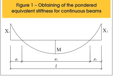
According to the ACI Committee 435 [5], the equivalent stiffness can be obtained with greater precision, for spans with continuous beams, by pondering the equivalent stiffness values of the regions. Thus, for the spans shown in igure [1], the value pondered for the equivalent stiffness is arrived at using:
(5)
(EI)
eq,pond= [(EI)
eq,1.
a
1+ (EI)
eq,2.
a
2+ (EI)
eq,3.
a
3] / l
where (EI)eq,i represents the equivalent stiffness of the three re-gions in the igure [1]. In each of the rere-gions, the equivalent stiff-ness should be calculated using the equation (2), using the values X1, M and X2, respectively, for Ma.
In order to determine the inertia moment for the cracked section III in the equation (2), elastic and linear behavior was admitted for the steel and concrete being compressed, while disregarding the concrete tension (igure [2]).
The section should initially be homogenized, using the following relationship between the steel and concrete elasticity modulus:
3. Equivalent stiffness according
to the Branson formula [1]
In the case of reinforced concrete beams, different amounts of reinforcement and the variable distribution of cracking along the span mean that stiffness against EI bending will not be constant.
According to NBR 6118:2007 [2], veriication of rotations and dis-placements in linear structural elements must be performed using models that take into account the effective stiffness of the cross sections of the elements, taking into consideration the presence of reinforcement, the cracking of the concrete along this reinforce-ment and the strainsover time.
Branson [1] presents an empirical expression in order to determine the effective stiffness in any particular cross section of a beam. This effective stiffness is a function of the bending moment, the section’s properties and the concrete strength.
The equivalent stiffness produced by Branson’s formula [1], which has been adopted by NBR 6118:2007 [2], for an approxi-mate assessment of the immediate delection in beams may be written as follows:
(2)
c cs II a r ca r cs
eq
E
M
M
I
M
M
I
E
I
EI
£
ïþ
ï
ý
ü
ïî
ï
í
ì
ú
ú
û
ù
ê
ê
ë
é
÷÷
ø
ö
çç
è
æ
-+
÷÷
ø
ö
çç
è
æ
=
3 3
1
)
(
where:
- Ecs is the secant concrete elasticity modulus, arrived at using:
(3)
E
cs= 0.85 E
ciwith Eci deined by the equation (1);
- Ic is the inertia moment for the gross section of concrete; - III is the inertia moment for the cracked section of concrete in state II;
- Ma is the bending moment in the critical section of the span being considered, the maximum moment in the span for beams with two
Figure 1 – Obtaining of the pondered
equivalent stiffness for continuous beams
a
1a
2a
3X
M
1
X
2Figure 2 – Cracked section (state II)
A
d'
a
e sx
IId
a
eA'
s(6)
α
e= E
s/ E
csNext, the depth of the neutral axis in state II, xII, was obtained, equalizing the static moment of the area above the neutral axis (Qsup) with the area below (Qinf). Thus, we have:
(7)
Q
sup= Q
inf(8)
[(b
.
xII)
.
xII/2 –
A’s
.
(xII
–
d’)] + α
e.
A’s
.
(xII
–
d’) = α
e.
As
.
(d – xII)
(9)
(b
.
x
II)
.
x
II/2 + (α
e–
1)
.
A’
s.
(x
II–
d’) = α
e.
A
s.
(d –
x
II)
Replacing
(10)
α’
e= α
e– 1
in equation (9), the following second degree equation in xII is obtained:
(11)
(b/2)
.
xII
2+ (αe
.
As
+ α’e
.
A’s)
.
xII
–
(αe
.
As
.
d + α’e
.
A’s
d’) = 0
which results in:
(12)
xII = – A + (A
2+ B)
½with
(13)
A = (α
e.
A
s+ α’
e.
A’
s)/b
(14)
B = 2
.
(
α
e.
A
s.
d +
α
’
e.
A’
sd’)/b
For the inertia moment for cracked section III, the result is:
(15)
I
II= (b/3)
.
x
II3+
α
’
e.
A’
s.
(x
II–
d’)
2+
α
e.
A
s.
(d –
x
II)
2It is important to mention that the equation (2) should only be uti-lized when the bending moment Ma is equal to or in excess of the cracking moment Mr, or that is, when Mr/Ma≤1 (state II). When Mr/ Ma > 1, the structure is already in state I and, therefore, the
stiff-ness of gross section EcsIc must be utilized.
Supposing, for example, that Mr/Ma = 0.5, the equation (2) is:
(16)
(EI)
eq= E
cs.
{(0.5)
3.
I
c+ [1 – (0.5)
3]
.
I
II}
(17)
(EI)
eq= E
cs.
(0.125
.
I
c+ 0.875
.
I
II)
Note that, in this case, the equivalent stiffness (EI)eq is determined, predominantly, by the stiffness of the cracked section (EI)II, with the contribution from the stiffness corresponding to the section of gross concrete being greatly reduced. It is common, therefore, for Ma/Mr relationships in excess of 2 to adopt an approximation of (EI)eq equal to(EI)II.
4. Numeric applications
In this paper, various plane frames belonging to regular reinforced concrete buildings (the typical stories used in these buildings can be found in Oliveira [6]) are analyzed using the inite element meth-od utilizing ANSYS 9.0 software. Table [1] summarizes the main characteristics of the examples studied.
Initially, linear elastic analyses of the buildings were performed utiliz-ing three-dimensional models. The load actutiliz-ing on the structures was divided into two groups: the vertical load and the horizontal load. The vertical load is composed of permanent loads and of the ac-cidental load. The permanent loads considered were the weight of the structure itself, masonry loads and the slab coatings and inishings.
The horizontal load is constituted of the loads equivalent to the action of the wind, in the directions parallel to the X and Y axes. The drag forces were calculated in accordance with the NBR 6123:1988 [7] Brazilian Norm and the ultimate normal combina-tions followed the rules established in NBR 6118:2007 [2]. The reinforcement of the columns and beams that constituted the frames being studied was determined based on the envelope of the efforts obtained for each load combination. The beams were dimensioned to combined axial load and bending and the columns to combined axial load and bending or to combined axial load and biaxial bending. CA-50 steel was used for all the structural ele-ments, with an elasticity modulus equal to 210 GPa.
geo-metric and physical nonlinearities. The load parcel corresponding to the combination that considered the wind (which acts parallel to
the X or Y axes, depending on the direction of the frame analyzed)
was applied as the main variable action. The wind load amounts that the frames received were calculated in function of their lateral stiffness values.
Within the diverse constitutive nonlinear models offered by AN-SYS, two stand out as being more appropriate for representing the behavior of concrete: the elastoplastic model based on the Druck-er-Prager yield criterion and the speciic model for the determina-tion of the failure of brittle materials, obtained using the Willam-Warnke criterion. For the steel, one can choose from between the bilinear or multilinear models, cinematic or isotropic, with or without hardening, according to the Von Mises yield criterion.
The utilization of the model based on the Willam-Warnke failure criterion is limited to a single element, deined as “solid 65”. This is a solid three-dimensional element, with eight nodes and three degrees of freedom per node (three translations, in the X, Y and Z directions). It is possible to consider the brittle failure associated with cracking and crushing of the concrete, also admitting consid-eration of elastoplastic behavior based on Drucker-Prager and Von Mises criteria. There is a possibility of including the reinforcement as a smeared material in the interior of the element, oriented ac-cording to three different directions.
In this example the “solid 65” element with smeared reinforcement (in three directions) was utilized in order to represent the columns and beams. The Willam-Warnke criterion allows for the failure con-dition to be deactivated and replaced with a plastiication concon-dition, utilizing, for example, the Drucker-Prager or Von Mises criteria. In the analysis performed, the Willam-Warnke failure criterion was maintained for concrete tension and the Von Mises yield criterion was employed for concrete compression and for the steel. It is im-portant to mention that the Von Mises criterion present, both for concrete and for steel, perfect elastoplastic behavior according to bilinear stress-strain diagrams. In reality, with the goal of avoiding possible numerical dificulties, minimum hardening was considered and a small value was adopted for the tangent modulus in place of zero. It should be noted that the parameters utilized in the non-linear analyses (materials models, discretization adopted and nu-meric resources involved) were “calibrated” based on various stud-ies of structural components and reinforced concrete frames that had already been tested experimentally, as was done by Oliveira & Silva [8] and Oliveira [6]. Such studies have revealed the
prox-imity between the experimental results and those obtained from the nonlinear geometric and physical analyses performed using ANSYS, which are therefore considered capable of representing the actual behavior of structures with a good degree of precision.
In order to perform the nonlinear analyses, ANSYS utilizes the Newton-Raphson incremental-iterative method. In this, the num-ber of load increments and the numnum-ber of iterations for each load step are supplied. Based on a known equilibrium coniguration and on load increment data, the structure will respond with a force level below that applied, which results in a residual force that must be applied again, observing the admitted iteration and tolerance lim-its. In this manner, the stiffness matrix may or may not be updated with each iteration, depending on the option desired by the user. Utilized in these processes were the full Newton-Raphson algo-rithm, automatic load increments and a limit of 60 iterations per increment, with a tolerance of 0.1% applied to the square root of the sum of the squares of force imbalances.
Nonlinear geometric analyses of the frames were also performed, considering the approximated physical nonlinearity, by means of a reduction in the stiffness of the structural elements. In the case of the columns, the stiffness was reduced by 20% and, for the beams, inertia reduction values were used in accordance with the Branson formula [1] and those recommended in NBR 6118:2007 [2]. Thus, the following values for the effective inertia of the structural elements were adopted:
• Icl = 0.8 Icand Ibm = 0.4 Ic;
• Icl = 0.8 Ic and Ibm = 0.5 Ic;
• Icl = 0.8 Ic and Ibm = Ieqarrived at using equation (2), or that is:
(18)
c II 3 a r c 3 a req
M
I
I
M
1
I
M
M
I
£
ú
ú
û
ù
ê
ê
ë
é
÷
ø
ö
ç
è
æ
-+
÷
ø
ö
ç
è
æ
=
In this case, the equivalent inertia values pondered were determined using various applied load percentages (P). In this manner, the per-formance of the Branson inertia equivalent [1] used to consider the physical nonlinearity of the beams in simple formcould be assessed for the loads corresponding to the ultimate limit state (deined as 100% P), the service limit state (considered to be approximately equal to 45% P) and for the unfactored loading (75% P).
In order to conduct the nonlinear geometric analyses of the frames using the ANSYS-9.0 software, the columns and beams
Table 1 – Main characteristics of the examples studied
Example
of stories
Number
Story height
(m)
Number
of spans
Span length
(m)
(MPa)
fck
1
16
2.90
2
6.0
20
2
20
Variable
3
Variable
40
3
20
2.75
4
Variable
45
4
30
2.85
2
7.5
20
5
16
2.88
2
6.0
25
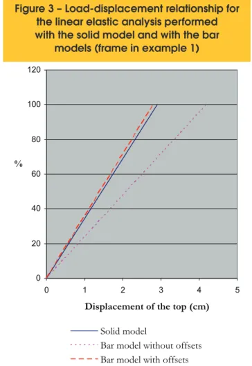
were represented using the bar elements, with three degrees of freedom in each node: two translations in the X and Y directions and one rotation about the Z axis. It is important to mention that, in the solid model, the beam spans are measured between the column faces, which makes it more rigid than the model for the bars, in which the spans are considered as extending from support axis to support axis. This difference creates a need to utilize the element deined as “beam 54” to represent the ex-tremities of the beams in the bar model. This element allows for the introduction of offsets in the beam-column joint region, making them rigid. As a result, it is possible to compare the two models under equal conditions. It is worth noting that, in or-der to determine the lengths of the rigid regions to be adopted, comparative analyses (linear elastic) were performed between the solid model and the bar model that utilizes offsets. Figure [3] presents the graph of the applied load versus horizontal dis-placement of the top of the frame in example 1 for the linear elastic analysis performed with the solid model and with the bar models (with and without offsets). It was observed that the bar model without offsets is really much more lexible than the solid model; this, in turn, is much better represented by the bar model that utilizes offsets.
Graphs were created that show the variation in horizontal dis-placement of the tops of the frames with the load applied, for
Figure 3 – Load-displacement relationship for
the linear elastic analysis performed
with the solid model and with the bar
models (frame in example 1)
0 20 40 60 80 100 120
0 1 2 3 4 5
Displacement of
the top
(cm)
%
Solid model
Bar model without offsets
Bar model with offsets
Figure 4 – Load-displacement relationship for
the nonlinear analyses (frame in example 2)
nonlinear geometric and physical analyses (NLGPA) and non-linear geometric analyses, with a simpliied representation of the physical nonlinearity (NLGA – SIMP. PNL). The graphs for the frames in examples 2, 3 and 4 are presented in igures [4], [5] and [6] (the other graphs, corresponding to examples
1, 5 and 6 can be found in Oliveira [6]). Based on the analysis of the load x displacement graphs, it was possible to visual-ize the reduction in inertia that better describes the behavior of the frames studied, considering the unfactored loading and the load that correspond to the ultimate limit and service limit states (table [2]).
Note that in table [2], in the service limit state, the analyses per-formed with Icl = 0.8 Ic and Ibm = Ieq according to Branson [1] and Icl = 0.8 Ic and Ibm = 0.5 Ic were shown to be more appropriate for representing the behavior of 83% and 67% of the frames studied, respectively. Therefore, for this load intensity, the analysis that uti-lizes reductions in inertia equal to 0.8 Ic for the columns and Ieq according to Branson [1] for the beams may be considered the most eficient.
Also in table [2], it was observed that, for the unfactored load-ing and that correspondload-ing to the ultimate limit state, in the majority of the examples analyzed, the utilization of the in-ertia reduction values adopted in NBR 6118:2007 [2] for the more general cases, or that is, Icl = 0.8 Ic and Ibm = 0.4 Ic, produced the results that best approximated those obtained through the nonlinear geometric and physical analysis. It was also observed that for only examples 2 and 6 the analysis per-formed using Icl = 0.8 Ic and Ibm = I
eq according to Branson
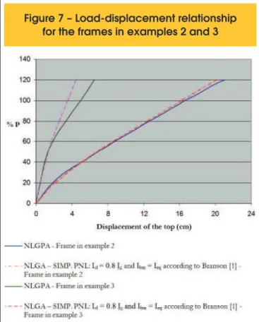
[1] represented the greatest degree of precision for the “ac-tual” behavior of the structures. It is worth mentioning that the frames in example 2 and 6, among all the frames analyzed, were the most flexible, as can be seen in the graphs in figures [7] and [8]. In these graphs, the load x displacement curves for the frames that present similar heights are confronted. Thus, figure [7] represents the variation in horizontal displacement at the tops of the frames in examples 2 and 3 with the load applied for the nonlinear geometric and physical analyses (NL-GPA) and nonlinear geometric analyses that utilize Icl = 0.8 Ic
Figure 6 – Load-displacement relationship for
the nonlinear analyses (frame in example 4)
Table 2 – Inertia reduction that better describes the behavior of the frames studied
Example
Load corresponding to
the service limit state (45% P)
Unfactored loading
(75% P)
ultimate limit state (100% P)
Load corresponding to the
1
I = 0.8 I
cl cand
I = 0.5 I
bm cI
cl= 0.8 I
cand
= 0.4 I
I
bm cI
cl= 0 8 I
.
cand
= 0 4 I
I
bm.
c2
I
cl= 0.8 I
cand
= I
I
bm eqaccording to Branson [1]
I
cl= 0.8 I
cand
= I
I
bm eqaccording to Branson [1]
I
cl= 0 8 I
.
cand
= I
I
bm eqaccording to Branson [1]
3
I
cl= 0.8 I
cand
= I
I
bm eqaccording to Branson [1]
I
cl= 0 8 I
.
cand
= 0 4 I
I
bm.
cI
.
and
I
.
cl
= 0 8 I
c= 0 4 I
bm c4
I
cl= 0 8 I
.
cand
= 0 4 I
I
bm.
cI
cl= 0 8 I
.
cand
= 0 4 I
I
bm.
c5
I
cl= 0 8 I
.
cand
= 0 4 I
I
bm.
cI
cl= 0 8 I e = 0 4 I
.
cI
bm.
c6
I
cl= 0 8 I
.
cand
= 0 4 I
I
bm.
cI
cl= 0 8 I
.
cand
= 0 5 I
I
bm.
cI
cl= 0 8 I
.
cand
= I
I
bm eqaccording to Branson [1]
I
cl= 0 8 I e = I
.
cI
bm eqaccording to Branson [1]
I = 0.8 I and I = I
cl c bm eqaccording to Branson [1]
I = 0.8 and I = 0.5 I
cl Ic bm cI = 0.8 I and I = I
cl c bm eqaccording to Branson [1]
I = 0.8 I and I = 0.5 I
cl c bm cI = 0.8 I and I = I
cl c bm eqand Ibm = Ieq according to Branson [1]. Analogously, figure [8] presents the variation in horizontal displacement of the tops of the frames in examples 5 and 6 with the load applied, also for the nonlinear geometric and physical analyses (NLGPA) and nonlinear geometric analyses that utilize Icl = 0.8 Icand Ibm = Ieq according to Branson [1].
In an analysis of the graphs in igures [7] and [8], it can be seen that, in fact, the utilization of inertia values equal to Icl = 0.8 Icand Ibm = Ieq according to Branson [1] is much more eficient for the rep-resentation of the behavior of the more lexible frames in examples 2 and 6 than for the stiffer frames in examples 3 and 5. This is cer-tainly due to the Branson inertia equivalent formula [1] itself, which consists of a ponderation of the inertias in the gross concrete sec-tion (state I) and cracked concrete secsec-tion (state II). The greater
the M
a/Mr relationship, the greater is the contribution from inertia in
the cracked section III. In the event the moment Ma is smaller than the cracking moment Mr, the inertia from the gross section of con-crete Ic is adopted for Branson’s inertia equivalent [1].
The frames in examples 2 and 6 present beams with lower inertia and have cracking moments Mr that are greatly inferior to those of the frames in examples 3 and 5, as is shown in table [3]. This means that the moments Ma will surpass the cracking moments Mr much more quickly for the frames in examples 2 and 6 than for the frames in examples 3 and 5; in the latter, therefore, Branson’s inertia equivalent [1] approximates the inertia for the gross section of concrete, even for greater load intensities, which may result in values that do not translate the actual loss of stiffness in the struc-ture. In the case of the frames in examples 2 and 6, based on the lower load values, the equivalent inertia shall be determined, in
large part, by the inertia for the cracked section III, which is coher-ent for structures with less stiffness and, therefore, with a greater cracking intensity.
It should be mentioned that, considering the small load intensities, from which the structures had not yet cracked, the analyses per-formed using Icl = 0.8 Ic and Ibm = I
eq according to Branson [1]
rep-resent a good degree of precision regarding the behavior of all the frames, both the more lexible ones and the stiffer ones (igures [7] and [8]). This is predictable, since, for the small load values P, the bending moments Ma are inferior to the cracking moment Mr and, consequently, the inertia value for the gross section of concrete Ic is adopted for Branson’s inertia equivalent [1].
5. Final considerations
This paper attempts to evaluate the eficiency of Branson’s inertia equivalent [1] to consider the physical nonlinearity of beams in simple form. To this end, various numerical analyses of plane frames belonging to regular reinforced concrete buildings were performed utilizing ANSYS software. Initially, the frames were processed considering both the geometric and physical non-linearities. Next, nonlinear geometric analyses were performed considering an approximated physical nonlinearity, by means of a reduction in the stiffness of the structural elements. In the case of the columns, the stiffness was reduced by 20% and, for the beams, the inertia reduction values according to the Branson formula [1] and those recommended in NBR 6118:2007 [2] were utilized. The results of the nonlinear geometric analyses, con-sidering the simpliied physical nonlinearity, were then compared
Figure 8 – Load-displacement relationship
for the frames in examples 5 and 6
Figure 7 – Load-displacement relationship
Table 3 – Cracking moments of beams
of the frames in examples 2, 3, 5 and 6
Example
Cracking moment M (kN cm)
r •
2
2625
3
6840
5
6370
6
2080
with those obtained using the nonlinear geometric and physical analyses, which are capable of representing the actual behavior of structures with greater precision.
The performance of the nonlinear geometric analyses, considering the simpliied physical nonlinearity, was evaluated for the loads corresponding to the ultimate limit state (deined as 100% P), the service limit state (considered approximately equal to 45% P) and for the unfactored loading (75% P).
In the service limit state, the analysis that utilizes inertia reductions equal to 0.8 Ic for the columns and Ieq according to Branson [1] for the beams may be considered the most eficient.
For the unfactored loading and the one corresponding to the ulti-mate limit state, the majority of the examples analyzed, the utiliza-tion of the inertia reducutiliza-tion values adopted in NBR 6118:2007 [2] for the more general cases, or that is, Icl = 0.8 Ic and Ibm = 0.4 Ic, produced the closest results to those obtained through the nonlin-ear geometric and physical analysis.
It is worth mentioning that the utilization of values equal to Icl = 0.8 Ic and Ibm = Ieq according to Branson [1] was shown to be more efi-cient for representing the behavior of the more lexible frames than for the stiffer frames. This is certainly due to the Branson inertia equivalent formula [1] itself, which for the stiffer frames, approxi-mates the inertia of the gross concrete section, even for greater load intensities, and may result in values that do not translate the actual loss of stiffness in the structure. In the case of the more lex-ible frames, based on the lower load values, the inertia equivalent shall be determined, in large part, by the inertia of the cracked section III, which is coherent for the structures with smaller stiffness values and, thus, with greater cracking intensity.
It was also noted that, for small load intensities, under which the structures had not yet cracked, the analyses performed using Icl = 0.8 Ic and Ibm = Ieq according to Branson [1] represented the behavior of all the frames, both the more lexible ones and the stiffer ones, with a good degree of precision. This can be ex-plained by remembering that, for small load values, the bending moments Ma are lower than the cracking moment Mr and, con-sequently, the inertia values for the gross section of concrete Ic is adopted for the Branson inertia equivalent [1].
Finally, starting with the principle that the stiffness reduction coef-icients for the structural elements are normally aimed at normal building projects, generally dimensioned for the load correspond-ing to the ultimate limit state, one may consider the inertia reduc-tions as being equal to 0.8 Ic for the columns and 0.4 Ic for the beams as being the most representative of the behavior of the frames analyzed. It should also be noted that the utilization of a constant coeficient for all the beams results in a simpler procedure
that is practical and easy to employ and is extremely advantageous compared with the utilization of the Branson inertia equivalent [1], which represents different values for each span and for each story of the building structure.
6. Bibliographical references
[01] BRANSON, D.E. Delections of reinforced concrete lexural members. Journal of the American Concrete Institute, n.6331, p.637-667, 1966.
[02] ASSOCIAÇÃO BRASILEIRA DE NORMAS TÉCNICAS.NBR 6118 – Projeto de estruturas de concreto - Procedimento. Rio de Janeiro, 2007. [03] PINTO, R.S.; RAMALHO, M.A.; CORRÊA, M.R.S.
Consideração simpliicada da não-linearidade física no projeto de edifícios de concreto armado. In: CONGRESSO BRASILEIRO DO CONCRETO, 40., Rio de Janeiro. Anais, 1998.
[04] LIMA, J.S. Veriicações da punção e da estabilidade global em edifícios de concreto: desenvolvimento e aplicação de recomendações normativas.
São Carlos. Dissertação (Mestrado) – Escola de Engenharia de São Carlos, Universidade de São Paulo, 2001.
[05] AMERICAN CONCRETE INSTITUTE – ACI
COMMITTEE 435. Delections of continuous concrete beams. ACI Journal, Report nº 70-70, December, 1973.
[06] OLIVEIRA, D.M. Estudo dos processos aproximados utilizados para a consideração das não-linearidades física e geométrica na análise global das estruturas de concreto armado. Belo Horizonte. Tese
(Doutorado) – Escola de Engenharia da Universidade Federal de Minas Gerais, 2007.
[07] ASSOCIAÇÃO BRASILEIRA DE NORMAS TÉCNICAS.NBR 6123 – Forças devidas ao vento em ediicações. Rio de Janeiro, 1988.