Daniel Deodato Lopes
Degree in Chemical Engineer
Preparação de micropartículas porosas com gás
e Microbolhas através do método de PGSS
Preparation of Gas-filled Porous microparticles
(GPPs) and Microbubbles (MBs) by PGSS
method
Dissertation to obtain the Master Degree in
Biotechnology
Thesis evaluation committee:
Chairman: Prof. Dr. Rui Freitas de Oliveira
Main Opponent: Prof. Dr. Catarina Maria Martins Duarte
Deputy: Dr. Manuel Nunes da Ponte
III
Copyright
Preparation of Gas filled porous microparticles (GPPs) and microbubbles (MBs) by PGSS method
em nome de Daniel Deodato Lopes , da FCT/UNL e da UNL.
“A Faculdade de Ciências e Tecnologia e a Universidade Nova de Lisboa tem o direito, perpétuo e sem limites geográficos, de arquivar e publicar esta dissertação através de exemplares impressos reproduzidos em papel ou de forma digital, ou por qualquer outro meio conhecido ou que venha a ser inventado, e de a divulgar através de repositórios científicos e de admitir a sua cópia e distribuição com objectivos educacionais ou de investigação, não comerciais, desde que seja dado crédito ao autor e
V
De tudo ficam três coisas
A certeza que estamos sempre a começar…
A certeza de que precisamos continuar…
A certeza de seremos interrompidos antes de terminar…
Portanto devemos: fazer da interrupção um
caminho novo…
Da queda, um passo de dança…
Do medo, uma escada…
Do sonho, uma ponte…
Da procura, um encontro…
Pedras no caminho? Guardo-
as todas, um dia vou construir um castelo…
Porque tenho em mim todos os sonhos do mundo
VII
Agradecimentos
A realização deste estágio só foi possível devido à interação entre a Faculdade de Ciências e
Tecnologia-Universidade Nova de Lisboa e o Instituto de Tecnologia Química e Biológica e o
Instituto de Biologia Experimental e Tecnológica
Agradeço à minha orientadora Doutora Catarina Duarte, pela oportunidade que me deu ao
realizar este estágio, a todo o apoio, orientação e bem como todos os conhecimentos por ela
transmitidos e partilhados.
Agradeço à Doutora Soraya Rodríguez-Rojo por todo o seu apoio, partilha de conhecimento,
orientação e um muito obrigado por toda a sua disponibilidade para comigo.
Agradeço à Doutora Helena Matias do grupo Cermax pela disponibilidade dos equipamentos e
pelos esclarecimentos prestados.
Agradeço à Doutora Isabel Nogueira do Laboratório ICEMS do Instituto Superior Técnico pela
disponibilidade dos equipamentos e pelos esclarecimentos prestados.
Agradeço à Doutora Ana Ricardo, minha orientadora de estágio da Faculdade de Ciências e
Tecnologia da Universidade Nova de Lisboa
Agradeço aos meus colegas do Laboratório Marta Fraile, Ana Nunes Nunes, Ana Patrícia
Almeida, Agostinho Alexandre, Cátia Carmo, Vanessa Gonçalves, pelo apoio, ajuda, simpatia,
conhecimentos partilhados e pelo companheirismo.
Agradeço a todas outras do Laboratório dos Nutracêuticos e Libertação controlada do (sétimo
piso), pelo apoio, ajuda e companheirismo.
Agradeço a todos os meus amigos pelo apoio e força que sempre me deram.
Por último mas não menos importante, agradeço aos meus pais, irmão, sobrinha e demais
família pelo apoio e auxílio que me deram para que conseguisse atingir os meus objetivos, sem
IX
Abstract
The main goal of this Project was the development of microbubbles (MBs) and gas-filled
porous particles (GPPs) by supercritical fluids (SCF) processes, namely particles from gas
saturated solution (PGSS).
MBs of perfluorcarbons (PFC) are currently used as contrast agents in ultrasound
imaging and as ultrasound-guided drug delivery for targeted therapeutic applications. They are
normally produced by processes that present some limitations. The SCF processes are an
innovative technology for the production of these MB’s that has not yet been exploited and can
overcome these limitations.
Carriers are used to prevent rapid diffusion of the gas out of the particle. In the first part
of this thesis, a preliminary selection of carrier materials was carried out, including lipids of
different hydrophilic-lipophilic balance (HLB) and hydrophilic polymers. Their behavior in the
presence of PFC and mixtures of PFC and sc-CO2 was qualitatively studied. A lipid of high HLB
value, Gelucire 50/13, was selected to produce the GPPs by PGSS. Main parameters of the
process, temperature and pressure, were studied in the range from 55ºC to 80ºC and from 8,5
MPa to 15,4 MPa. Besides, the carrier:PFC ratio and the molecular structure of the PFC were
investigated. Particle morphology was analyzed by Scanning Electron Microscopy (SEM), and
the presence of PFC was determined by Nuclear Magnetic Resonance (NMR). Small and non
agglomerated particles were obtained at 80ºC and 8.5 MPa.
Cyclic C4F8 was entrapped in lipid particles in higher amount than of linear C3F8.
Nevertheless, the stability of particles obtained at the best operating conditions (80ºC and 8.5
MPa), was relatively short (below 3h) being the majority of the gas released in the first hour.
XI
Resumo
O principal objectivo deste projecto foi o desenvolvimento de microbolhas (MBs) com
núcleos de gás e/ou partículas porosas (GPP) também com núcleos de gás. Este projecto foi
desenvolvido utilizando processos de fluidos supercríticos (SCF), nomeadamente, precipitação
de soluções saturadas com gás (CO2) (PGSS).
As MBs de perfluorcarbonetos (PFC) que são actualmente utilizados como agentes de
contraste em imagiologia de ultrassons, são normalmente produzidos por processos que
apresentam algumas limitações. Os SCF serão uma tecnologia inovadora para a produção
destas MBs, que ainda não foi explorada.
O material de revestimento é utilizado para evitar a rápida difusão do gás para fora da
partícula. Foi realizada uma seleção preliminar de lípidos com diferentes valores
hidrofílico-lipofílico (HLB) para materiais de revestimento. O comportamento desse material foi
qualitativamente estudado na presença de PFC e misturas de PFC e sc-CO2. Um lípido de
elevado valor de HLB, Gelucire 50/13, foi selecionado para produzir estas partículas porosas
através do método PGSS. Os principais parâmetros do processo foram; temperatura e pressão
com um intervalo de temperatura de 55 º C a 80 º C e um intervalo de pressão de 8,5 MPa a
15,4 MPa. As partículas mais promissoras, foram produzidas com as seguintes condições de
pressão e temperatura: 8,5 MPa e 80ºC, respectivamente. Além disso a influência da razão do
material de revestimento PFCs e estrutura molecular destes foram estudados. A morfologia das
partículas foram analisadas por microscopia electrónica de varrimento (SEM), e para a
detecção dos PFCs foi utilizado a Ressonância Magnética Nuclear (NMR).
O PFC cíclico C4F8 foi encapsulado em partículas lipídicas com maior quantidade do
que o PFC linear C3F8. No entanto, a estabilidade das partículas obtidas nas condições nas
melhores condições (8,5 MPa e 80 º C), foi ainda relativamente curto (inferior a 3 horas),
sendo a maior parte do gás libertado durante a primeira hora.
XIII
Index
Agradecimentos ... VII
Abstract ... IX
Resumo ... XI
Index ...XIII
List of images ... XV
List of tables ... XVII
Acronyms ... XIX
1. Introduction ... 1
2. Aim ... 3
3. Theoretical Backgroung ... 5
3.1 Microbubble Structure ... 5
3.2 Perfluorcarbons ... 6
3.3 Conventional methods of production ... 7
3.4 Applications on the medical field ... 9
3.5 Supercritical fluids methods ... 10
3.5.1 Supercritical fluids properties ... 10
3.5.2 CO2 as Supercritical fluid ... 12
3.5.3 Particle engineering with supercritical fluid ... 12
3.5.4 Particle gas saturated solution (PGSS) ... 13
3.6 Methods for characterization of MBs ... 16
3.6.1 Nuclear Magnetic Resonance ... 16
3.6.2 Scanning Electron Microscopy (SEM) ... 16
4. Material and methods ... 17
4.1 Materials ... 17
4.2 High pressure Visual Cell apparatus ... 18
4.3 PGSS process apparatus ... 18
4.3.1 Calibration of PFC filling system ... 19
4.4 NMR Analysis at Cermax Group ... 21
4.5 Scanning Electron Microscopy (SEM) ... 21
5. Results and discussion ... 1
5.1 Phase Equilibrium ... 1
5.2 PGSS experiments results ... 1
5.2.1 Effect of temperature and pressure ... 1
5.2.2 Effect of Gelucire: PFC ratio ... 1
5.2.3 Effect of gas structure ... 1
5.2.4 Stability of the gas in the particle ... 1
6. Conclusion and Future Work ... 3
XV
List of images
Figure 3.2: A. Cyclic Perfluorcarbon: Octafluorcyclobutane (C4F8). B. Linear perfluorcarbon:
Octafluorbutane (C3F8) ... 7
Figure 3.3: Rupture of drug loaded MBs by application of ultrasounds U.S. (Ferrara, K., et al.,
2007). ... 9
Figure 3.4: A. Supercritical CO2 diagram. B. CO2 density-pressure phase diagram ... 10
Figure 3.5: Particles from Gas Saturated Solutions (PGSS) techniques. (Nunes A. et al., 2011)
... 14
Figure 3.6: Influence of pressure (bar) and Temperature (K) on morphologies of PEG 6000
particles process by semicontinous PGSS with a GTP ratio of 4 (Lack, E., et al., 2010). ... 15
Figure 3.7: Schematic representation of the diffusion of CO2 out of the droplets formed (Sousa,
A. R., 2007)... 15
Figure 5.5: NMR spectra analysis of Gelucire 50/13: C4F8 particles produce with different
operating conditions and fix carrier: PFC ratio of 40:1 ... 1
Figure 5.6: NMR spectra analysis of Gelucire 50/13 particles produce at 85ºC and 80 bar in all
ratios carrier:C4F8, ... 1
Figure 5.7: Effect of CO2 amount in relative amount of PFC gas entrapment ... 1
Figure 5.8: NMR spectra analysis of Gelucire 50/13 particles produce at 85ºC and 8,0 MPa in all
ratios carrier:C3F8, ... 1
Figure 5.9: NMR analysis of Gelucire 50/13 particles produce at 85ºC and 8,0 MPa for a
carrier:PFC ratio of 30:1. Stability study: red line (0h; particles after production), green line (1h)
XVII
List of tables
Table 3.1: Critical parameters of selected compounds (Pasquali,I., et al., 2007) ... 11
Table 3.2: Comparison of properties of gases, supercritical fluids and liquids ... 11
Table 4.1: Features of carrier compounds ... 17
Table 4.2: Physical properties of gases – Octafluorpropane C3F8, octafluorcyclobutane C4F8.. 17
Table 4.3: Results of the volume, mean and standard deviation, according to calibration
procedure ... 20
Table 5.1: Behavior of the carriers in the presence of both PFCs. ... 2
Table 5.2: Bulk density of MBs obtained at different operation conditions ... 1
Table 5.3: Operating conditions and amount of each component for PGSS experiments with
different ratios Gelucire:C4F8 ... 1
Table 5.4: Operating conditions and amount of each component for PGSS experiments with
XIX
Acronyms
CPF - Concentrated powder form
DMPC - (dimyristoyl phosphatidylcholine)
DPPA - (dipalmitoyl phosphoric acid)
DPPC - (dipalmitoyl phosphatidylcholine)
DPPG - (1,2-dipamiltoyl-sn-glycero-3- phosphoglycerol)
DPSC - (1,2-distearoyl-sn-glycero-3- phosphocholine)
GAS - Gaseous Anti-Solvent
GMS - glyceryl monosterate
GPPs - porous microparticles with gas
HAS- Human serum albumin
HLB- Hydrophobic lipophilic Balance
MBs- Microbubbles
MPEG 5000-DPPE - (polyethyleneglycol 5000-dipalmitoyl phosphotidylethanolamine)
NMR - Nuclear molecular resonance
PAH- poly(allylamine hydrochloride)
PA-palmitic acid
PEG –polyethylenoglycol
PDMS- Polydimethylsiloxane
PFC- Perfluorcarbons
PGSS - Particles from gas saturated solutions
PLGA - (polylactide-co-glycolide)
RESS - Rapid Expansion Saturated Solutions
SAS - Supercritcial Fluid Anti-Solvent
SCF- supercritical fluids
SEM - Scanning electron microscopy
Preparation of Gas Filled Porous Microparticles (GPPs) and Microbubbles (MBs) by PGSS
1 September, 2012
1. Introduction
Supercritical fluids have been widely studied for the encapsulation of solids in natural or
synthetic polymers, lipids or carbohydrates (Cocero M. J., et al, 2009). Moreover, liquids have
been also encapsulated by means of the PGSS (Particles from Saturated solutions) process
(Wendt, T., et al, 2005). However, the entrapment of gas has not been addressed before
through these processes. Thus, the main goal of this project is to explore the potential of
supercritical fluids to produce Gas-filled Porous Particles (GPPs) and MicroBubbles (MBs).
MBs, composed by a filling gas, namely a perfluorocarbon (PFC), and a coating material or
shell, are used as contrast agents in ultrasound imaging. Besides, they are being studied as
ultrasound-guided drug delivery devices for the treatment of cancer, cardiovascular and
pulmonary diseases (Cavalieri, F., et al, 2008) (Stride, E., and Edirisinghe, M.).
Current production methods of MBs generally involved the formation of an emulsion using
organic solvents, such xylene or toluene (Tinkov S., et al, 2009) (Stride E., and Edirisinghe, M.,
2008). These techniques offer high yield and low cost production; however, the control over size
particle is poor and new processed are being explored to overcome this drawback (Stride E.,
and Edirisinghe, M.) as well as their short half-life, i.e. the gas diffuses out the MBs through the
coating material (Lentacker, J. et al., 2006) ( Sirsi, S. and Borden, M., 2007).
Supercritical fluids for particle engineering, namely PGSS process, presents an environmentally
friendly alternative for the manufacture of MBs and GPPs that will avoid the used of organic
solvents; In PGSS, the supercritical fluid, sc-CO2, is dissolved partly in the molten carrier,
reducing its viscosity. After rapid expansion of the mixture through a nozzle, particles are
Preparation of Gas Filled Porous Microparticles (GPPs) and Microbubbles (MBs) by PGSS
3 September, 2012
2. Aim
The project aims to explore the capability of supercritical fluids to encapsulate gas
inside of microparticles to produce gas-filled porous particles (GPPs) and microbubbles (MBs),
Preparation of Gas Filled Porous Microparticles (GPPs) and Microbubbles (MBs) by PGSS
5 September, 2012
3. Theoretical Backgroung
3.1 Microbubble Structure
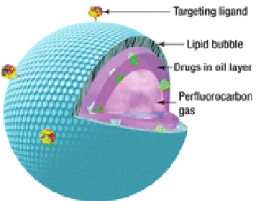
Microbubbles are spherical voids or cavities filled with gas used as contrast agent in U.S. imaging. They are formed by two main of components: filling gas and coating material. Besides, they can be used as target drug delivery devices (Unger E.C. et al., 2004). In this
case, a drug can be incorporated in the MB and the coating material can have targeting ligands (Figure 3.1).
Figure 3.1: Microbubble (from Liu Y. et al., 2006)
There have been three generations of MBs. Firstly MBs were simple air bubbles without any stabilizing shell. In the second generation, a stabilizing shell was introduced; however, as the filling gas was air or N2, MBs half life was short, less than 5 minutes, as these gases are
sparingly soluble in blood. MBs with a gas core of perfluorocarbons (PFCs) were the third generation. This gas core, which is chemical and physiologically inert and practically insoluble in water, increases the half-life of MBs (Tinkov, S. et al., 2009).
The coating or shell material of MBs is essential for their stabilization against coalescence and dissolution, and to control the size and morphology of the particles produced (Unger E. C. et al., 2004). The coating materials can be proteins (Human serum Albumin,
Albumin (Ferrara K. et al., 2007, Tsutsui J.M. et al., 2004, Unger E. C. et al., 2004, Tinkov, S et al., 2009), lipids such as fatty acids (Tinkov, S. et al., 2009), and natural and synthetic polymers
such as poly-L-lactide (Yang, F. et al., 2007), cellulose, poly(allylamine hydrochloride)
(PAH)(Lentacker, J. et al., 2006), Polydimethylsiloxane (PDMS) (Hettiarachchi K. and Lee A.P.,
Preparation of Gas Filled Porous Microparticles (GPPs) and Microbubbles (MBs) by PGSS
6 September, 2012
phosphotidylethanolamine (MPEG 5000-DPPE), dimyristoyl phosphatidylcholine (DMPC), polylactide-co-glycolide (PLGA) (Tinkov et al., 2009), Also, a combination of polymer-lipid or
polymer-protein can be used (Hettiarchchi K. and Lee A.P., 2010).
There is a wide variety of ligands that could be incorporated in microbubbles’ shell to
lead to different targets. Some examples are avidin-biotin, antibodies, DNA, magnetic beads, (Hettiarachchi et al., 2010), oligonucleotides, intracellular leukocyte (Tsutsui, J et al., 2004). The
ligands can be incorporated through electrostatics or hydrophobic interactions, van der Waals forces or by physical encapsulation. Hydrophilic macromolecules such as RNA and DNA, can be coupled to the surface of microbubbles, while the amphiphilic molecules are able to penetrate the monolayer of particles. (Tinkov, S. et al., 2009). Drug molecules can be also
encapsulated into shells of biodegradable materials
As mentioned before, the gas core of MBs can be air, N2 or most commonly,
perfluorcarbons. Most used perfluorocarbons are octofluoropropane (C3F8),
octofluorocyclobutane (C4F8) and decafluorobutane (C4F10). Also, sulfure hexafluoride (SF6) is
widely used, although it is slightly soluble in water compromising the stability of the MB. Besides, some liquid fluoroalkanes are also used: dodecafluoropentane (C5F12), which became
gas above 29.5ºC at atmospheric pressure, and tetradecafluorohexane (C6F14) (Tinkov, S. et
al., 2009) (Unger E.C. et al., 2004).
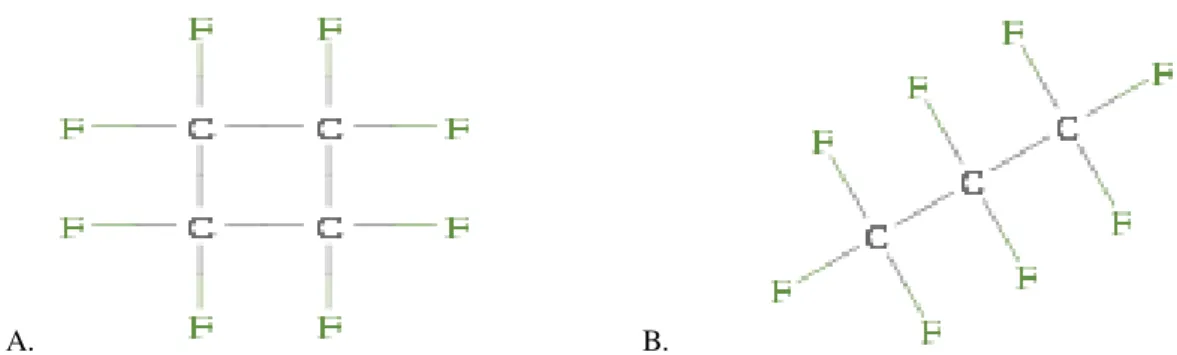
3.2 Perfluorcarbons
Perfluorcarbons are linear, cyclic, or polycyclic fluorine substituted hydrocarbons (figure 3.2). These gases have been proved to be a good choice as microbubbles gas fillers, since they are chemically and biologically inert. In addition, these gases are non polar, amphiphilic, non-ozone depleting, colorless, odorless, non-toxic and non-flammable materials not requiring any special handling procedures (Sandford G. et al., 2008) (Kaneda M.M. et al., 2009) (Gomes L.
and Gomes E.R., 2007). Moreover, PFCs are used in gas delivery therapeutics thanks to their capacity to dissolve great amounts of gases (O2, CO2 and N2). The solubility of O2 in PFC liquids
at 37ºC and 1 atm is of 40 to 50 % (v/v) while for CO2 this percentage rises to about 200 % (v/v)
Preparation of Gas Filled Porous Microparticles (GPPs) and Microbubbles (MBs) by PGSS
7 September, 2012
A. B.
Figure 3.1: A. Cyclic Perfluorcarbon: Octafluorcyclobutane (C4F8). B. Linear perfluorcarbon:
Octafluorbutane (C3F8)
For medical applications, PFCs can be formulated as gas core in MBs and as PFC water emulsions. Some applications of these applications are artificial liquid ventilation as oxygen carriers, contrast agent in MIR-imaging and controlled drug delivery (Gomes L. and Gomes E.R., 2007).
3.3 Conventional methods of production
The microbubbles have already been produced by conventional techniques. Formulation of MBs is made by emulsions, such as nano or microemulsions of perfluorcarbons, stabilized by biodegradable block copolymer surfactants and loaded with drugs. Sonication, high shear emulsification, and mechanical agitation are some methods developed to produce microbubbles that are already marketed (Yang F. et al., 2007) (Tinkov, S. et al., 2009). These
techniques offer high yield and low cost production, being these factors very important in the industry. However, they have poor control over microbubble size and uniformity (Stride, E., and Edirisinghe, M., 2008).
New production methods, which provide a high degree of control over microbubble size, composition, stability and uniformity, are being developed: membrane emulsification, inkjet printing, electrohydrodynamic atomization and microfluidic processing (Hettiarachchi, K and Lee A. P., 2010) (Stride, E., and Edirisinghe, M., 2008).
Sonication is the most commonly used method for microbubble preparation with protein shell; this method involves dispersing the gas or liquid in suspension with a suitable coating material using high intensity ultrasound. Firstly, the gas or liquid is emulsified to form a suspension micro droplets or bubbles (Stride, E. and Edirisinghe, M., 2008) (Tinkov, S. et al.,
Preparation of Gas Filled Porous Microparticles (GPPs) and Microbubbles (MBs) by PGSS
8 September, 2012
High shear emulsification method is commonly used for preparing polymer coated microbubbles. An aqueous emulsion of the polymer, dissolved in a suitable solvent, is formed by high shear stirring. An immiscible non volatile liquid is used as a stabilizer. After solvent evaporation, the polymer precipitates onto the surface of the droplets to from coated liquid filled microspheres. The liquid filled may be only removed partially if the microspheres were to be used therapeutically (Stride, E., and Edirisinghe, M., 2008)
Mechanical agitation is a two-step process. Initially, the shell of microbubble is produced through of a conventional method; then, the dispersion is placed into vials, filled with a suitable gas, which will later form the core of the MB. The vials are shaken at several thousand oscillations per minute (Tinkov, S. et al., 2009).
The spray-drying method is used to form void particles. During particle formation, the
coating material solidifies on the droplet’s surface to form the shell while the solvent inside the
droplet evaporates (Tinkov et al., 2009).
Microfluidic devices have been recently used to prepare microbubbles in suspensions, although the preparation of monodisperse liquid droplets is well established. Gas bubbles are formed by the impingement of a gas column into a liquid flow through a small orifice. Subsequently, at a certain distance of the orifice, the gas-liquid interface becomes unstable and an isolated bubble is formed. These devices offer operational control, but pressure and flow rate conditions are very limited (Stride, E., and Edirisinghe, M., 2008).
The membrane emulsification is an alternative to others methods such as sonication and high shear stirring. In this method, emulsion components are force flow through a porous membrane, sometimes repeatedly, to produce the emulsion. Gas microbubbles may be formed directly by using gas as the disperse phase. The advantage of this method is that it offers greater control over microbubbles size and narrower size distribution compared with the others techniques, without significantly reducing the yield of microbubbles (Stride, E., and Edirisinghe, M. 2008).
Ink jet printing is another technique to improve the microbubbles uniformity. Droplets of
the fluid to be ‘printed’ are formed when this fluid is forced out of a stainless steel nozzle (20 -50µm in diameter) by the pressure pulses generated by a piezoelectric crystal embedded in the fluid. The droplets can be collected in air or in a liquid container. The advantage of this method relatively to membrane emulsification and microfluidic techniques is that droplet size can be varied by simply changing the electric voltage applied across the piezoelectric element; hence, varying the frequency/length of the pressure pulses (Stride, E., and Edirisinghe, M., 2008).
Preparation of Gas Filled Porous Microparticles (GPPs) and Microbubbles (MBs) by PGSS
9 September, 2012
3.4 Applications on the medical field
As mentioned before, MBs are already used as contrast agents for U.S. imaging and diagnostics (Guidi, F., et al. 2010) (Vos H.J., et al., 2007); Thanks to its gas core, MBs are
compressible and have the potential to respond to acoustic and ultrasound excitations: as the sound travels more slowly in gases than it does in liquids. MBs create an acoustic impedance mismatch between tissue and blood surroundings, where the MBs are suspended. (Hettiarchchi, K. and Lee, A.P., 2010). Moreover, if the gas core is a PFC, they are also used in Magnetic Resonance Imaging (MRI) since the 19F atom exhibits high Nuclear Magnetic Resonance (NMR) sensitivity, with essentially no background signal within the body (Kaneda M. M., et al., 2009.). Their introduction into clinical applications led to the development of more
sensitive imaging techniques both in cardiology and radiology. Their use in medicine today is essential for disease diagnosis (Tinkov,S., et al., 2008). (Cavalieri F., et al., 2008).
In both applications, MBs are administered through intravenous injection; therefore, particle size should be below 5-10 micron to avoid vasculature damaging.
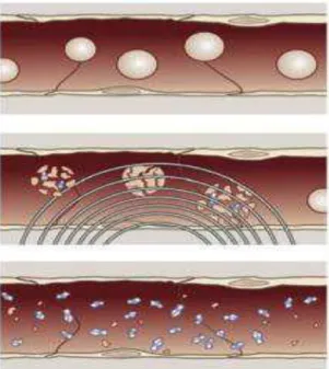
Moreover, MBs are being studied for ultrasound triggered drug delivery (Figure 3.3). After intravenous injection, MBs as U.S. imaging contrast agents, freely circulated throughout the vasculature under low pressure pulses. When MBs reach the target organ, stronger ultrasound pulses are applied to destroy them. The drug is, thus, release and easier absorbed by cells (Ferrara, K., et al. 2007). The ligands incorporated onto the surface of MBs, enable
targeting to cell-specific receptors for more precise therapy with U.S (Unger, E. C., et al., 2004).
Furthermore the microbubbles in combination with ultrasounds may increase transiently the permeability of various biological barriers, such as blood-brain-barrier (Ferrara K., et al., 2007).
Preparation of Gas Filled Porous Microparticles (GPPs) and Microbubbles (MBs) by PGSS
10 September, 2012
Besides the intravenous injection, there are other important administration routes as via nasal, for drug delivery into the lungs. The lungs are an important target of PFC microbubbles, for the treatment of many chronic diseases such as asthma; cystic fibrosis; interstitial pneumonitis and interstitial fibrosis. Microbubbles composed of a film of a drug with PFC inside, have low density and unique properties for pulmonary delivery (Unger, E. C. et al., 2004).
3.5 Supercritical fluids methods
The supercritical fluid technology is a clean and environmentally friendly technology since it reduces the use of organic solvents and leaves no residue in the final products, which eliminates traditional post-steps process, such as washing or drying. It is therefore, considered an excellent alternative to the use of organic solvents, so that in the past 25 years it has been widely applied in the development of drug delivery systems (Cravo, C. et al., 2006) (Pasquali, I. et al., 2007) (Belhadj-Ahmed, F., et al., 2009) (Cocero, J.M., et al., 2009).
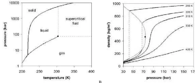
3.5.1Supercritical fluids properties
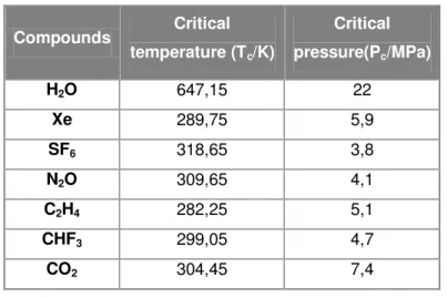
A supercritical fluid (SCF) is a substance whose temperature and pressure are above their critical values (Figure 3.4A). The critical values of temperature and pressure (Table 3.1) increase with molecular weight and intermolecular hydrogen bonds or polarity. The thermophysical properties of supercritical fluids (density, viscosity and diffusivity) are intermediated of those of liquids and gases (Table 3.2). Since the surface tension is almost zero, there is no longer separation between liquid and gas phases; thus, SCF exist as a single phase, with the macroscopic appearance of a homogeneous and translucent system (Pasquali, I., et al., 2007) (York, P. 1999).
A. B.
Preparation of Gas Filled Porous Microparticles (GPPs) and Microbubbles (MBs) by PGSS
11 September, 2012
The SCF is dense but highly compressible, particularly near the supercritical region. Thus any change of pressure or temperature alters its density and, consequently, the solvent power of the fluid. In Figure 3.4B is possible to verify that for temperatures approaching the critical temperature a small variation in pressure causes a large change in density, unlike what happens at much higher temperatures. Similarly, at pressures near the critical pressure, a small change in temperature causes a very significant change in density, which no longer occurs at very high pressures. It is concluded that near the critical point the density is particularly sensitive to small changes in the values of pressure and temperature.
These unique features make it possible for the fluid to penetrate a matrix like a gas and still have the solvent power of a liquid, qualifying this technology as interesting for different
Table 3.1: Critical parameters of selected compounds (Pasquali,I., et al., 2007)
Compounds Critical
temperature (Tc/K)
Critical
pressure(Pc/MPa)
H2O 647,15 22
Xe 289,75 5,9
SF6 318,65 3,8
N2O 309,65 4,1
C2H4 282,25 5,1
CHF3 299,05 4,7
CO2 304,45 7,4
Table 3.2: Comparison of properties of gases, supercritical fluids and liquids
Viscosity (Pa.s) Density (g/mL) Diffusivity
(cm2/s)
Gas 10-5 10-3 0,1
Supercritical
Fluid 10
-4
0,3 10-3
Preparation of Gas Filled Porous Microparticles (GPPs) and Microbubbles (MBs) by PGSS
12 September, 2012
industrial applications, like extraction and catalysis (Sousa, A.R., 2007). Moreover, some compounds with low critical temperature, such CO2, are specially indicated for the food,
cosmetic and pharmaceutical industry, to avoid thermal degradation of its components. Nevertheless, SCF technologies applied to particle engineering are not yet widespread throughout industry which is likely due to the high cost of the equipment and the weak knowledge.
3.5.2 CO2 as Supercritical fluid
Carbon dioxide is the supercritical fluid chosen in more than 98 % of applications for particle engineering (Pasquali, I., et al., 2007). Since the critical pressure and temperature,
(Table 2) are easily attainable and enable to process temperature sensitive products, such as most of the products of biological origin and application. Additionally, CO2 has the added
benefits of its inert nature, non-toxicity, low cost, wide availability and recyclability, and it is readily separated from the products (Cocero M. J. et al., 2009) (Pasquali, I., et al.,2007), (Cravo,
C., et al., 2006)( York, P. 1999) (Nunes, A. et al. 2011).
Due to its non-polar behavior, carbon dioxide has little affinity for polar compounds; solubility of high molecular weight compound is also limited. Far from being a disadvantage, CO2 can be used as selective solvent or as an anti-solvent or solute, depending on the
applications and the phase equilibrium between the CO2 and compound of interest.
Nevertheless, solubility can be increased by the addition of a co-solvent such as water, ethanol or methanol (Belhadj-Ahmed, F. et al.., 2009).
Besides, compressed CO2 has excellent plasticizing properties and can swell most
polymeric matrixes; Thus, active substances or additives can be incorporated into polymers by impregnation under mild operation conditions (Cravo, C., et al., 2006).
.
3.5.3Particle engineering with supercritical fluid
The production of particles, i.e. a drug or drug mixture with carrier molecules for localized administration, whose physical characteristics (size, morphology, structure,
dispersibility, physicochemical stability) are optimized is called ‘particle engineering’ (Chow
A.H.L, et al., 2007). Thus, for drugs formulation, it will improve the bioavailability and controlled
release of the drug.
Particle formation processes using supercritical fluids, namely sc-CO2, have emerged in
the over a decade as a promising alternative technology to overcome some technical problems and limitations related to the use conventional methodologies. Some of these processes are spray drying or emulsification-evaporation techniques, which most important drawbacks are the use of high temperatures, high shear forces and organic solvents (Nunes, A. et al, 2011). In
Preparation of Gas Filled Porous Microparticles (GPPs) and Microbubbles (MBs) by PGSS
13 September, 2012
degradation. In addition, a SCF particle engineering process improve the control of particle properties, require less handling and simplifies cleaning and sterilization post- steps (Rogers T.L., et al., 2001).
There are several techniques for particle engineering and micronization with supercritical fluids. These processes are classified according to the role of the SCF as solvent (RESS), anti-solvent (SAS) or solute (PGSS) (Cocero, M.J. et al., 2009).
In RESS (Rapid Expansion of Supercritical Solution) process, the solute to be micronized is dissolved in the SCF and, then, this solution is expanded through a nozzle into a chamber at atmospheric conditions. The rapid depressurization produce a high supersaturation of the solute and fine particles are produced (Rogers, T.L., et al., 2001).
In SAS (Supercritical fluid as Anti-Solvent) process, the product is dissolved in an organic solvent; the precipitation of particles is performed by the addition of SCF; therefore, the effect of sc-CO2 as anti-solvent is exploited (Weidner, E., et al., 2010) (Cocero, M.J., et al,
2009).
In PGSS (Particles from Saturated Solution), the compounds are melted and mixed with sc-CO2, that dissolves partly in the melt and reduces its viscosity. Afterwards, this melt is
expanded via a nozzle into a spray tower and particles are formed by solidification due to the Joule-Thompson effect (Lack, E., et al., 2010) (Cocero, M.J., et al., 2009).
The solubility of a solute in supercritical fluids is related to its physical and chemical properties, such as polarity, molecular structure, and nature of the particle material and fluid supercritical fluid chosen. Besides, the operating conditions, such as temperature, pressure, density of solvent and co-solvents have also influence (Montes, A. et al., 2011). The very low
solubility of solids in CO2 makes the RESS process unattractive, however the SAS process
very attractive because the solute must not be soluble in the SCF. Also, supercritical carbon dioxide can be dissolved in many polymers and lipids to be processed by PGSS or PGSS-derived methods (Nunes, A., et al., 2011)
PGSS process will be explained in detail, since this project explores its use in the production of lipid and polymer gas filled porous particles. It was selected taking into account
the plasticizing properties of CO2.
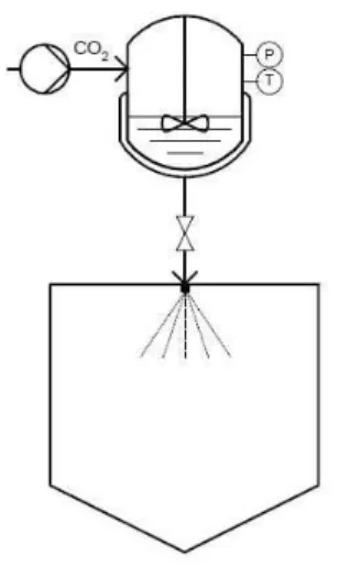
3.5.4Particle gas saturated solution (PGSS)
As mentioned before, in the PGSS method, the particles are produced through the expansion of gas saturated solutions through nozzle into a spray tower. The compounds are melted and mixed with the dense or sc-CO2, either in a pressure vessel (batch process, Figure
3.5) or in a static mixer (continuous process) (Lack, E., et al., 2010).
The solubilization of SC-CO2 lowers the melting point of the compounds, reduces the
Preparation of Gas Filled Porous Microparticles (GPPs) and Microbubbles (MBs) by PGSS
14 September, 2012
is very fast due to the direct heat transfer from particles into the CO2, which is at the same time
cooled down by the expansion (Joule-Thomson effect). Therefore, the thermal stress is lower compared to classic air drying process (Lack, E., et al., 2010).
Figure 3.4: Particles from Gas Saturated Solutions (PGSS) techniques. (Nunes A. et al., 2011)
These features have been exploited in the mixture, coating and encapsulation of food and pharmaceutical products, without requiring the use of organic solvents, avoid thermal degradation and air oxidation (Jung, J. and Perrut, M., 2001) (Lack, E., et al., 2010). Moreover, PGSS process is simple, easily scalable, and production cost (energy and gas consumption) is lower in comparison with other SCF process, such as RESS (Tandya A., et al., 2007).
As mentioned before, particle size and morphology of PGSS product, in both continuous and batch processes, is directly related to the degassing of the admixed and dissolved CO2 in the molten compound.Therefore, pressure and temperature are identified as
main process parameters, since sc-CO2 solubility depends on them.
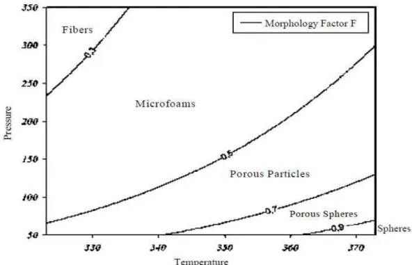
The effect of pressure and temperature in continuous PGSS processing, as well as the mass flow ratio of CO2 to product solution (GTP ratio), was extensively studied by (Kappler, P.,
et al., 2003) using polyethyleneglycol PEG as reference material. They demonstrated that
Preparation of Gas Filled Porous Microparticles (GPPs) and Microbubbles (MBs) by PGSS
15 September, 2012
Figure 3.5: Influence of pressure (bar) and Temperature (K) on morphologies of PEG 6000 particles process by semicontinous PGSS with a GTP ratio of 4 (Lack, E., et al., 2010).
As pressure is increased, larger amounts of CO2 are dissolved in the melt and higher
pressure drop is produced across the nozzle; therefore, more CO2 gas bubbles are formed
increasing the cooling rate (Joule-Thomson effect) which originate micro-foams and porous particles as the gas cannot diffuse out of the particles perforating particle surface (Figure 3.7). On the contrary, as temperature increased, the solubility of CO2 is decreased allowing the
formation of more spherical structures since the slower solidification of the droplets facilitates the diffusion of CO2 out of the particles (Kappler, P., et al., 2003)(Lack, E., et al., 2010) (Sousa,
A. R., 2007).
Figure 3.6: Schematic representation of the diffusion of CO2 out of the droplets formed
Preparation of Gas Filled Porous Microparticles (GPPs) and Microbubbles (MBs) by PGSS
16 September, 2012
3.6 Methods for characterization of MBs
The particles obtained in the experimental work of this thesis, were analyzed in terms of gas entrapment, which was qualitatively analyzed by Nuclear Magnetic Resonance (NMR), and particle morphology, analyzed through Scanning Electron Microscopy (SEM)
3.6.1 Nuclear Magnetic Resonance
NMR was chosen to detect PFC inside the particles due to its high sensitivity for fluorine atom (19F) (Kaneda, M. M., et al., 2009).
NMR is based on a phenomenon that occurs when the nuclei of certain atoms are immersed in a static magnetic field and exposed to a second oscillating magnetic field of a specific frequency in the range of MHz of the electromagnetic spectra. NMR phenomenon allows studying physical, chemical and biological properties of matter, such as chemical structure of molecules based on the energy absorbed by the substance understudy (Hornak, P.J., 1997).
NMR can only be applied to atoms with appropriate nuclear spin. Spin is a fundamental property like electric charge or mass. It takes values multiples of ½, positive or negative. Protons and neutrons, as electrons, posses spin; individual unpair protons and electrons each posses a nuclear spin of ½. Compounds that have more number of spins scattered more the energy and the generated NMR signal is worse. Almost every element of the table periodic has an isotope with a nuclei spin different of zero. This method can only be performed when the isotopes have a natural abundance sufficiently high to be detected (Hornak, P.J., 1997).
Fluorine atom (19F) has a net spin of ½, with one unpaired proton and no unpaired neutrons, like 1H. The natural abundance of 19F isotope of fluorine is near to 100%, having a receptivity signal of 4,89x10². Also, the signal strength of 19F is high, being approximately 83%
that of 1H (Kaneda, M. M., et al., 2009).
3.6.2 Scanning Electron Microscopy (SEM)
SEM was used to observe particle size and morphology. This technique allows to characterize the particles, on a nano scale (nm) or micro scale (µm) due to high spatial
resolution (≈ 1 nm) and the wide range of available magnifications (≈ 20x to 100000x). Thus,
there are few instruments that have such a wide range of uses as electron microscopy, in its various configurations. Using this technique we can obtain images of surfaces of a large number of materials. SEM images are formed by an electron beam. This beam, which is generated at the top of the microscope, describes a helical path through lens in the
electromagnetic field, to focus on the sample surface, ‘sweeping it’. The interaction of this beam
Preparation of Gas Filled Porous Microparticles (GPPs) and Microbubbles (MBs) by PGSS
17 September, 2012
4. Material and methods
4.1 Materials
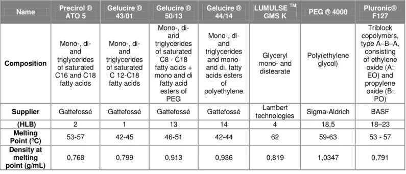
A preliminary selection of carrier materials was performed, including lipids of different hydrophilic-lipophilic balance (HLB) and hydrophilic polymers. Their properties are listed in Table 4.1.
The CO2, 99,95% of purity, was provided by Air Liquid (Portugal), as well as PFC, C3F8
and C4F8,both with 99,99% of purity. Their physical properties are shown in the Table 4.2.
Table 4.1: Features of carrier compounds
Name Precirol ® ATO 5 Gelucire ® 43/01 Gelucire ® 50/13 Gelucire ® 44/14
LUMULSE TM
GMS K PEG ® 4000
Pluronic® F127 Composition Mono-, di- and triglycerides of saturated C16 and C18
fatty acids Mono-, di- and triglycerides of saturated C 12-C18 fatty acids Mono-, di- and triglycerides of saturated C8 - C18 fatty acids + mono and di fatty acid esters of PEG Mono-, di- and triglycerides and mono- and di, fatty acids esters of polyethylene Glyceryl mono- and distearate Poly(ethylene glycol) Triblock copolymers, type A–B–A, consisting of ethylene oxide (A: EO) and propylene oxide (B: PO)
Supplier Gattefossé Gattefossé Gattefossé Gattefossé technologies Lambert Sigma-Aldrich BASF
(HLB) 2 1 13 14 4 18,5 18–23
Melting
Point (ºC) 53-57 42-45 46-51 42-44 62 59-63 53 - 57 Density at
melting point (g/mL)
0,768 0,799 0,913 0,936 0,819 1,0347 0,791
Table 3.2: Physical properties of gases – Octafluorpropane C3F8, octafluorcyclobutane C4F8
Gas Weight molecular Vapor pressure (MPa) at 20ºC Density at 23ºC (g/mL) Melting point (ºC) Boiling point (ºC) Critical temperature (ºC) Critical pressure (MPa) Molar volume (cm3/mol)
C3F8 188 0,77 1,3352 -183 -36,7 71,9 2,640 139
Preparation of Gas Filled Porous Microparticles (GPPs) and Microbubbles (MBs) by PGSS
18 September, 2012
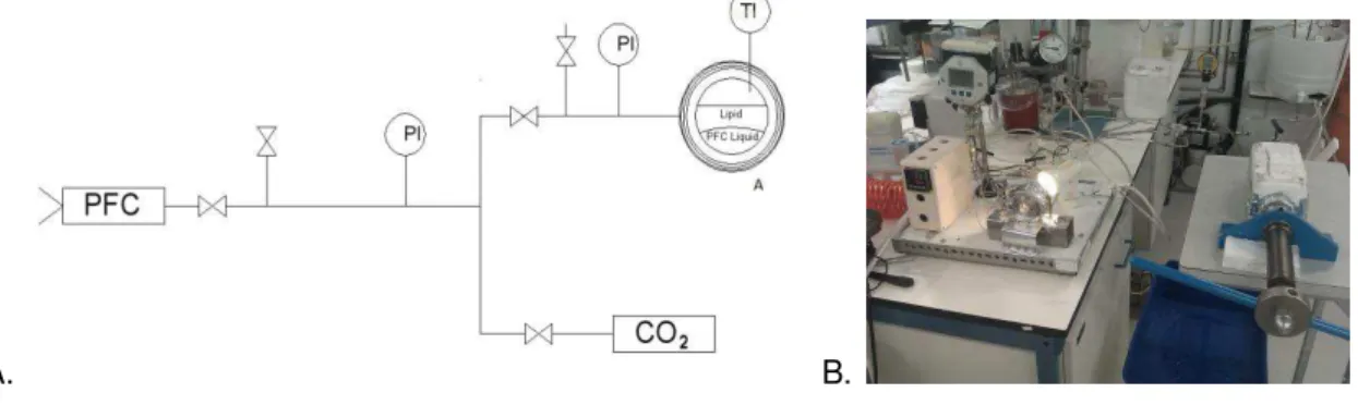
4.2 High pressure Visual Cell apparatus
A high pressure visual cell (Figure 4.1) was used to study the behavior of the carriers in the presence of the perfluorcarbons. Furthermore, the behavior of this mixture after the addition of SC-CO2 was observed. The apparatus consisted of 5 cm3-volume high pressure cell with
sapphire windows. The heating system was composed of a heating cable (Horst), a controller (Ero Electronic LMS) and a high accuracy thermometer (Omega HH 501 AT, 0,1%). The pressure in the cell was measured with a pressure transducer Digibar II calibrated between 0MPa and 25MPa (accuracy: 0,15%).
A. B.
The experiments were performed as follows: a sample of carrier (≈1g) was placed
inside in the high pressure cell. A small amount of dye (β-carotene) was added to the carrier, to easily distinguish it from the PFC liquid. The sample was melted at atmospheric pressure; afterwards the PFC was added. Finally, CO2 was injected into the binary system.
PFC was liquefied and pressurized in the piston of a manual syringe pump. This piston was inside an ice bath with liquid nitrogen.
The carbon dioxide was previously liquefied and pumped using a Haskel pump (model 29723-71).
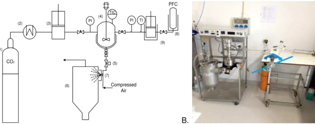
4.3 PGSS process apparatus
The apparatus used for the experiments (Figure 4.2) was built by Separex Supercritical & High Pressure Technology (2011,France). The apparatus comprises a high pressure vessel of 50 mL volume with two sapphire windows, a cyclone and a 18L collector vessel.
In a typical assay the mixture (CO2, carrier, PFC) was stirred at 170 rpm for 30min and
then depressurized through a nozzle (0,25 mm) into the cyclone, where it was mixed with compressed air (7 bar). Temperature was controlled by a system composed with a sensor inside the vessel, and the pressure was measured. The solid particles were collected and separated from carbon dioxide in cyclone. The system was designed for a maximum pressure of 35 MPa.
Preparation of Gas Filled Porous Microparticles (GPPs) and Microbubbles (MBs) by PGSS
19 September, 2012
A. B.
Figure 4.2: A. Experimental setup: (1) CO2 cylinder (2) cryostate (3) pneumatic piston pump (4)
stirred vessel (electrically thermostated) (5) automated depressurization valve (6) recovery vessel (7) nozzle (8) PFC vessel (9) manual high-pressure syringe pump. B. Picture of PGSS apparatus
PGSS experiments were carried out as follow: First, a certain amount of carrier was inserted inside the high pressure vessel. Secondly, the vessel was closed and the operating temperature was set. Moreover, the carrier was allowed to melt while stirring. After melting the carrier, the PFC was injected into the vessel using a calibrated filling system.
PFC was liquefied with liquid nitrogen and pressurized using a manual syringe pump with the valve at the outlet opened. The fluid was pressurized in the filling system, which volume is known (see section 4.3.1), until the desired pressure was achieved (ca. 12 MPa for C4F8 and
9 MPa for C3F8). Immediately after, the valve connecting to the PGSS pressure vessel is
opened and, at the same time, the valve at the outlet of the piston is closed. The variation of pressure in the filling system is registered and used to calculate the mass of PFC introduced. Density values of PFC are calculated from NIST data base.
PFC and the carrier were mixed for 30 minutes. Afterwards, CO2 was added until the
pressure setting for the experiment was reached. Subsequently, the three components were mixed for 30 minutes more. Finally, the mixture was expanded through the nozzle and particles were sprayed to the cyclone and collected at the bottom of the collector vessel.
4.3.1Calibration of PFC filling system
The mass of PFC used in the experiments was determined indirectly through compound density and occupied volume values. Therefore, it was necessary to calibrate of the volume the PFC piping system.
For the calibration, the system was coupled to a cylinder of 1,78L, previously calibrated with milli-Q water at 22ºC.
The apparatus (Figure 4.1) was divided in three sections as shown in Figure 4.3. The first section corresponds to the line connecting the cylinder submerged in a water bath at 22ºC
CO2 (1) (2) (3) (4) (5) (7) TIC (6) Compressed Air
PI PI TI
PFC
Preparation of Gas Filled Porous Microparticles (GPPs) and Microbubbles (MBs) by PGSS
20 September, 2012
with the filling system. This section had a low pressure manometer with a range of 0-25 psi (0 –
172 kPa) with an accuracy of 0,02 psi (0,13 kPa). The second section corresponds to the tubes and valves that connect the first section and the cylinder of the manual piston pump. This is the section of interest regarding the injection of PFC gas into the PGSS vessel. The third section, corresponds to the connection between the second section and the visual cell or the PGSS vessel.
Figure 4.3: High pressure Apparatus divided into three sections. (A) Heated sapphire window cell (B) calibrate cylinder in thermostated bath 1- First section 2- Second section 3
– Third section
Before proceeding with the calibration, it was necessary to evacuate the gas from the lines of the three sections, as well as, from the calibrated cylinder with a vacuum pump.
The cylinder was pressurized with nitrogen (N2), since this gas is inert and stable and
do not present any phase change. The moles number of the gas, was determined through the equation of ideal gas ( ), once the other variables were already known, Temperature (T), Pressure (P), Volume (V) and the ideal gas constant. The temperature used in the calculations was the room temperature, 22ºC.
The calibration was made by sections. The initial pressure inside the N2 cylinder before
of the calibration was 166 kPa. Firstly, the valve in the section 1 was open and pressure was allowed to stabilize and read in the manometer of section 1. Since the N2 mole number was
known, the volume of the section 1 was determined. Afterwards the process was repeated for section 2 (valve 2) and section 3 (valve 3).
The calibration procedure was repeated three times for each section. The result is presented in Table 4.3
Table 4.3: Results of the volume, mean and standard deviation, according to calibration procedure
Section 1 Section 2 Section 3
Mean (L) 0,006 0,011 0,003
Preparation of Gas Filled Porous Microparticles (GPPs) and Microbubbles (MBs) by PGSS
21 September, 2012
4.4 NMR Analysis at Cermax Group
The 19F NMR spectra were obtained on a BRUKE AVANCE II+ console and a 400 MHz Ultra-Shield-Plus Magnet with 54 mm diameter standard bore. The equipment was controlled via Topspin V.2.1 software and was run in automatic mode (ICON-NMR). It was equipped with a broad band 5 mm BBFO-Z probe-head for direct detection of 19F.
The spectrometer was operated at 376 MHz for direct observation of 19F at 25ºC. The NMR spectra were acquired with optimized parameters for which the 90º pulse width was 11 µs.
The acquisition time was 0.4375s over a total number of 10000 scans and the minimum recycling delay time was 0.5. The data were processed with an exponential multiplication corresponding to a 30 Hz signal width.
All fluorine atoms of C4F8 (4 x -CF2-) resonate at -138 ppm whereas C3F8 presented two
kind of fluorine atoms according to their nuclear environments: fluorine in (CF3) resonate at
-85ppm and those in (-CF2-) at -133 ppm. Therefore the spectral window was 37500 Hz (100
ppm) for C3F8 and 9400 Hz (25 ppm) for C4F8.
A sample of dry particles together with a capillary filled with D2O was introduced in a
NMR tube. The deuterium signal was necessary to keep constant the resonance frequency of the magnetic field of the equipment. In order to get comparable NMR spectra, the same amount of particles (ca. 0.9g) were carefully packed in the same volume of the NMR tube. Nevertheless, it was not possible to quantify the amount of the PFC in the particles, because the amount of these particles was not homogenous. Therefore, benzene was used as solvent, but it was neither possible to make a calibration curve since the solubility of the PFC gases was very small, i.e. 2.731·10-03 molar fraction of C
4F8 (Evans and Battino, 1971).
Consequently, the encapsulated amount of PFC was qualitatively analyzed by comparison of peak areas of samples obtained under different conditions.
4.5 Scanning Electron Microscopy (SEM)
Preparation of Gas Filled Porous Microparticles (GPPs) and Microbubbles (MBs) by PGSS
22 Septembre, 2012
5. Results and discussion
5.1 Phase Equilibrium
Using the high pressure visual cell (describe in 4.2), the behavior of the different carriers selected in the presence of each chosen perfluorcarbon, octafluorcyclobutane (C4F8) or
octafluorbutane (C3F8) was studied.
Through visual cell observations, it was possible to conclude that none of the PFC tested (C3F8 and C4F8) change the melting point of the carriers. Besides, both gases were
immiscible with all carriers. Nevertheless, some differences were found in the behavior of each binary system (carrier-PFC) due to density values of each compound. In some cases, the density of molten carrier was lower enough, that it has floated on the liquefied PFC. The same has happened for the system Gelucire 50/13-C4F8 (Figure 5.1). In other cases, both densities
were similar, so that the liquefied PFC and the molten polymer tried to stay at the same level.
This phenomenon was identified as “repulsion” since one of the components, depending on the surface tension values, leak to the walls while the other was in the centre of the cell (Figure 5.2).
.
Figure 5.2: Pluronic F127- C4F8
The behavior of each pair carrier-PFC is summarized in Table 5.1. It can be observed
that the “repulsion” is the predominant behavior of the systems with C3F8 since its liquid density
at test conditions (ca. 55ºC and 1,6 MPa) is around 1 g/mL (NIST), very similar to the values of molten carriers (Table 4.1). The density of C4F8 was higher: ca. 1,4 g/mL at 55ºC and 0,7 MPa.
This table also reports if an emulsion of both components could be formed. However, as the stirring was performed with a magnetic system, the emulsion formed was quite weak, with the exception of Gelucire 50/13. Moreover, it was not possible to stir high viscous systems (i.e PEG
4000, GMS and Pluroni F127).
Figure 5.1: Gelucire 50/13 - C4F8
PFC vapor
Preparation of Gas Filled Porous Microparticles (GPPs) and Microbubbles (MBs) by PGSS
23 Septembre, 2012
Table 5.1: Behavior of the carriers in the presence of both PFCs.
Carriers Position at
the cell
(C4F8)
Emulsion
(C4F8)
Carriers Position at
the cell
(C3F8)
Emulsion
(C3F8)
Gelucire
44/14 At the top Weak
Gelucire
44/14
At the
top/repulsion Weak
Gelucire
43/01 At the top Weak
Gelucire
43/01
At the
top/repulsion No
Gelucire
50/13 At the top Weak/mean
Gelucire
50/13
At the top
/repulsion Weak
PEG 4000 At the top No, very
viscous PEG 4000 repulsion
No, very viscous
Precirol ATO
5 Repulsion Weak
Precirol ATO
5 Repulsion No
GMS Repulsion No, very
viscous GMS Repulsion
No, very viscous
Pluronic F127 Repulsion No, very
viscous Pluronic F127
At the bottom/ repulsion
No, very viscous
The addition of CO2 up to 7,5 MPa has improved the mixing between the carrier and the
PFC. When CO2 was added to the binary system, still three phases were present: liquid PFC,
molten carrier and CO2 with the vapor PFC solubilized into it (Figure 5.3 A). After stirring, a
two-phase system was formed: CO2 partly dissolved in the carrier (Sousa, A. R., 2007) and in the
Preparation of Gas Filled Porous Microparticles (GPPs) and Microbubbles (MBs) by PGSS
24 Septembre, 2012
A. B.
5.2 PGSS experiments results
According to the previous results, the system Gelucire 50/13-PFC-CO2 was selected to
be processed by PGSS, as this carrier was the only one able to form a stable emulsion in equilibrium with the gaseous phase.
5.2.1Effect of temperature and pressure
The operating conditions, pressure and temperature, were varied in order to verify their effect on particle morphology and gas entrapment efficiency. The experiments were made with a fixed ratio Gelucire 50/13:PFC of 40:1 and at three different (P.T.) conditions
Taking Figure 5.4 as starting point, the approximate conditions to obtain micro-foams (15 MPa - 55ºC), porous particles (15 MPa - 80ºC) and porous spheres (8,5 MPa - 80ºC) were selected. Nevertheless, it should be noted that this figure was developed for continuous processing of PEG. Therefore, different regions are expected for the system in development.
As shown in Figure 5.4, particles produced at high pressure and low temperature (15 MPa - 55ºC) were larger particles, more porous and more agglomerated than those produced under different conditions. As expected, when temperature was increased (15, MPa- 80ºC) more spherical particles were produced. Furthermore, as pressure was decreased (8,5 MPa- 80ºC), less porous and less agglomerate particles were produce, since the amount of CO2
dissolved in the carrier was smaller. However, since particles were too porous and looked like broken in all cases, the carrier (Gelucire 50/13) was processed alone by PGSS as reference to determined if the observations were due to operation conditions or to burst release of PCF after particle solidification. As clearly shown in Figure 5.4, cavities were more abundant in particles processed with PFC.
Best operation conditions (8,5 MPa and 80ºC) were identified once they yielded small and low agglomerated spherical particles with good flowability. However, no difference was
Preparation of Gas Filled Porous Microparticles (GPPs) and Microbubbles (MBs) by PGSS
25 Septembre, 2012
observed in the bulk density of the powders. Values ranged from 0,230 g/mL to 0,274 g/mL (Table 5.2).
According to NMR analysis, the amount of encapsulated gas was very similar in these three experiments (Figure 5.5). Nevertheless, it could be said that the particles obtained at (8,5 MPa -80 ºC) had more gas inside than the others, according to the area of the peak. This could be explained, perhaps, due to their more spherical morphology, enabling more entrapment of the gas inside the particle. On the contrary, the more porous the microbubbles are, the less gas they retain. Particles obtained without PFC Particles obtained with PFC (Gelucire: PFC ratio: 1:12) 15,0 MPa 55ºC 15,0 MPa 80ºC 8,5 MPa 80ºC
Figure 5.4:SEM images of particles obtained by PGSS at different operating conditions. Scale bar: 30µm (top images) and 10 µm (bottom images)
Table 5.2: Bulk density of MBs obtained at different operation conditions
Conditions/ratio 15,0 MPa - 55ºC
(12:1)
15,0 MPa - 80 ºC
(12:1)
8,5 MPa - 80ºC
(12:1)
Preparation of Gas Filled Porous Microparticles (GPPs) and Microbubbles (MBs) by PGSS
26 Septembre, 2012
Figure 7: NMR spectra analysis of Gelucire 50/13: C4F8 particles produce with different operating
conditions and fix carrier: PFC ratio of 40:1
5.2.2 Effect of Gelucire: PFC ratio
Maintaining the operation conditions established in the previous section (8,5 MPa and 80ºC), various carrier:PFC gas ratios were tested in the range from 10:1 to 50:1. As detailed in Table 5.5, the total mass of carrier was varied, since the amount of PFC injected in the PGSS high pressure vessel could not be varied in a wide range, due to small volume of PFC filling system, as explained in section 4.3.1.
The PFC gas was detected in all formulations, except in ratio 10:1, as shown in NMR analysis (Figure 5.6). When the ratio was increased, the amount of PFC gas also increased, i.e. the area of the peak increases, up to the ratio of 30:1. For higher ratios, the amount of PFC gas decreases, being this tendency somehow expected, since the gas is more diluted in the lipid particle.
From the results, was clear that a higher amount of lipid is needed to encapsulate the PFC, when it is aimed to be entrapped in the gas phase. Nevertheless, these results could be not fully explained, since a quantification of the gas in the particles could not be performed and the knowledge about the phase equilibrium of the ternary mixture is only qualitatively known, according to visual cell experiments. Moreover, it should be taken into account that the amount of CO2 varies from one experiment to the other since the amount of lipid is different in some of
the experiments (Table 5.3).
8,5 MPa; 80ºC
15,0 MPa; 80ºC
Preparation of Gas Filled Porous Microparticles (GPPs) and Microbubbles (MBs) by PGSS
27 Septembre, 2012
Figure 8: NMR spectra analysis of Gelucire 50/13 particles produce at 85ºC and 80 bar in all ratios carrier:C4F8,
Table 5.3: Operating conditions and amount of each component for PGSS experiments with different ratios Gelucire:C4F8
Gelucire (g)
C4F8
(g) Ratio
Initial Pressure
(MPa)
Final Pressure
(MPa)
Temperature (ºC)
C4F8
detection
1,510 0,484 (3:1) 8,9 8,8 80 No
5,001 0,482 (10:1) 8,5 8,2 81 Yes
10,000 0,490 (20:1) 8.5 8,0 80 Yes
14,000 0,462 (30:1) 8.5 7,7 79 Yes
14,000 0,355 (40:1) 8-5 7,5 79 Yes
14,010 0,278 (50:1) 8.5 7,6 81 Yes
A rough calculation indicates that approximately 7.5g of CO2 were used in the (3:1)
experiment and that it was decrease of 10% between 1st and 2nd experiment, as well as
between the 2nd and 3rd, and between the 3rd and the 4th. Approximately, the same amount was
used in the 4th, 5th and 6th experiments. Since PFC is solubilized in the CO
2, the PFC dilution will
decrease as CO2 amount decreases, carrying more PFC into the molten material. On the other
Preparation of Gas Filled Porous Microparticles (GPPs) and Microbubbles (MBs) by PGSS
28 Septembre, 2012
carrier. These tendencies are shown in the graph below (Figure 5.7), where the % of NMR peak areas normalized by the area of the peak 30:1 represented for each carrier: PFC ratio.
Figure 9: Effect of CO2 amount in relative amount of PFC gas entrapment
5.2.3Effect of gas structure
Similar experiments were performed using the linear PFC (C3F8). Differences were
evident between both gases, being C3F8 less entrapped in the particles (Figure 5.8). This
difference could be explained, perhaps, due to the difference in the molecular structure. Due to the fact that C4F8 molecule is cyclic and C3F8 molecule is linear, it will be more difficult to leave
the porous spheres for a cyclic molecule than for a linear one.
Preparation of Gas Filled Porous Microparticles (GPPs) and Microbubbles (MBs) by PGSS
29 Septembre, 2012
It should be noted that C3F8 was only detected for the ratios: 10:1, 20:1, 30:1 (Table 5.4;
Figure 5.8). As discussed previously, higher amounts of C4F8 were also detected for these
three ratios. The same explanation could be applied for these results, since approximately the same amount of all components was used.
Table 5.4: Operating conditions and amount of each component for PGSS experiments with different ratios Gelucire:C3F8
Gelucire (g)
C3F8
(g) Ratio
Initial Pressure (MPa) Final Pressure (MPa) Temperature (ºC)
C3F8
detection
1,510 0,473 (3:1) 8,9 8,8 80 No
5,001 0,484 (10:1) 8,5 8,2 81 Yes
10,000 0,485 (20:1) 8.5 8,0 80 Yes
14,000 0,469 (30:1) 8.5 7,7 79 Yes
14,000 0,352 (40:1) 8-5 7,5 79 No
14,010 0,288 (50:1) 8.5 7,6 81 Yes
5.2.4 Stability of the gas in the particle
The stability of gas inside the particle was evaluated for particles at optimal operation conditions (8,5 MPa, 80 ºC and 30:1 carrier: PFC ratio). Dry particles were analyzed by NMR directly after production and after 1, 2 and 3 hours at room temperature.
The half-life of the gas inside the particle was shorter than 3 hours. As shown in Figure 5.9, the majority of the gas was release in the first hour.
Preparation of Gas Filled Porous Microparticles (GPPs) and Microbubbles (MBs) by PGSS
30 Septembre, 2012