Engineering ISSN: 1809-4430 (on-line)
_________________________
1 Part of the dissertation of the first author.
3 Federal University of Uberlândia/ Monte Carmelo - MG, Brazil. 4 Federal University of Pelotas/ Pelotas - RS, Brazil.
ESTIMATION OF THE KINETIC HEAD COEFFICIENT (k) BASED ON THE GEOMETRIC CHARACTERISTICS OF EMITTER PIPES1
Doi:http://dx.doi.org/10.1590/1809-4430-Eng.Agric.v37n6p1091-1102/2017
JOSÉ H. N. FLORES2*, OSVALDO RETTORE NETO3, LESSANDRO C. FARIA4,
LUÍS C. TIMM4
2* Corresponding author. Federal University of Pelotas/ Pelotas - RS, Brazil. E-mail: [email protected]
ABSTRACT: The objective of this study was to determine the variability of the head loss as a function of the emitter geometry as well as to develop a relation between local head loss caused by the emitter insertion and geometric characteristics of the emitter pipe, using index of obstruction for dripper pipes with non-coaxial emitters. For this, an experimental bench was developed to control the system and obtain the variables pertinent to the study. From the value of the total head loss in the emitter pipe and the value obtained with calculation of the distributed head loss in the pipe, the difference of these values was local head loss caused by the insertion of the emitter. Total head loss in the emitter pipe and local head loss on the emitter presented a potential relation with flow rate. The kinetic head coefficient (k), for each emitter studied, was obtained from the local head loss on the emitter and the kinetic head. A model for estimating the k coefficient based on the obstruction index was then generated.
KEYWORDS: non-coaxial emitters, obstruction index, trickle irrigation, head loss.
INTRODUCTION
The Brazilian irrigated area occupies approximately 4.5 million hectares, and is responsible for 16% of agricultural production and 35% of the economic value of the total production of the country (Paulino et al., 2011).
Trickle irrigation is highlighted in relation to the others irrigation methods, since it has the potential to present high indices of water application efficiency (Frizzone et al., 2012; Provenzano et al., 2013). Studies show the efficiency of trickle irrigation systems compared with the other systems, in different crops, without negatively influencing productivity (Andrade et al., 2014; Carvalho et al., 2014; Geisenhoff et al., 2015; Uribe et al., 2013).
The correct estimate of head loss is an important factor in trickle irrigation projects as it influences the total dynamic head, and in turn, in the choice of the pumping system (Cardoso & Frizzone, 2014). According to Al-Amoud (1995) one of the factors that interfere with the lateral line head loss is the obstruction caused by the emitter, which can increase the total head loss in the system by up to 33%.
The emitters are one of the main components of drip irrigation (Frizzone et al., 2012). The local head loss caused by the emitters can be estimated by the general equation of local head loss
which presents a portion k of the Bernoulli kinetic head (V2/2g) known as the Reynolds similarity
principle, and it is represented by Equation 1 (Azevedo Netto & Fernandes, 2015).
g 2
V k hf
2
where,
hfe - local head loss on the emitter, m;
k - kinetic head coefficient, dimensionless;
V - mean velocity at uniform pipe section, m s-1; and
g - acceleration of gravity, 9.806 m s-2.
The kinetic head coefficient (k) is dependent on the viscous forces and the emitter geometry. In studies carried out by Bagarello et al. (1997), Gomes et al. (2010), Provenzano et al. (2005) and Rettore Neto et al. (2009) it was evidenced that for conditions where Reynolds number (Re) is greater than 10,000 the viscous forces become negligible, thus, the obstruction becomes the main cause of the local head loss. In order to evaluate the head loss as a function of the obstruction, Bagarello et al. (1997) developed an exponential equation (Equation 2) based on the Obstruction Index (Equation 3). For this, the authors used the obstruction ratio (Equation 4) obtained through the obstructed area by the emitter and the pipe area.
OI
k (2)
2 2
r r -1 I
O (3)
0 r
A A
r (4)
where,
k - kinetic head coefficient, dimensionless; OI - obstruction index, dimensionless;
and - adjustment coefficients, dimensionless;
r - obstruction ratio, dimensionless;
A0 - pipe cross-section area, mm2, and
Ar - reduced pipe cross-section area on emitter insertion, mm2.
However, due to the large quantity and variety of emitter pipes on the market studies are needed to generate or improve models for estimating the kinetic head coefficient based on the emitter characteristics. In this sense, this study aims to determine the variability of head loss as a function of the emitter geometry as well as to develop relation between the local head loss caused by the emitter insertion and the geometric characteristics of the pipe through the use of obstruction index for emitter pipes with non-coaxial emitters.
MATERIAL AND METHODS
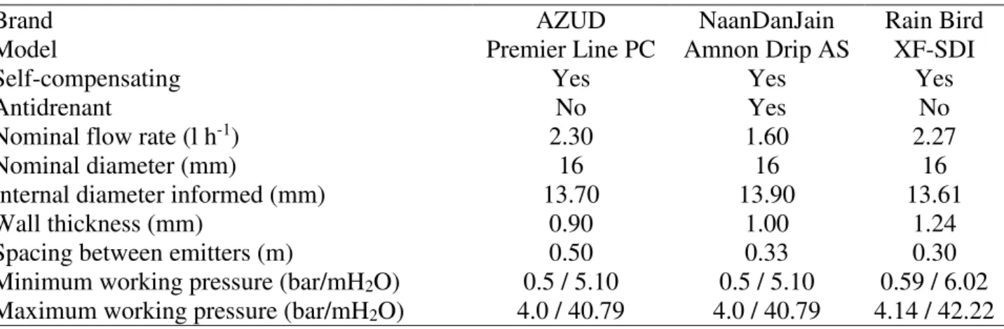
TABLE 1. Models of emitter pipes studied and technical characteristics according to the manufacturer.
Brand AZUD NaanDanJain Rain Bird
Model Premier Line PC Amnon Drip AS XF-SDI
Self-compensating Yes Yes Yes
Antidrenant No Yes No
Nominal flow rate (l h-1) 2.30 1.60 2.27
Nominal diameter (mm) 16 16 16
Internal diameter informed (mm) 13.70 13.90 13.61
Wall thickness (mm) 0.90 1.00 1.24
Spacing between emitters (m) 0.50 0.33 0.30
Minimum working pressure (bar/mH2O) 0.5 / 5.10 0.5 / 5.10 0.59 / 6.02
Maximum working pressure (bar/mH2O) 4.0 / 40.79 4.0 / 40.79 4.14 / 42.22
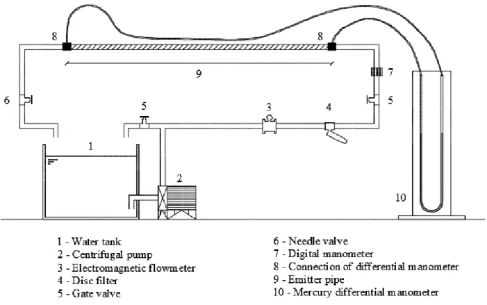
To conduct the study an experimental bench was used which had the necessary equipment to control the system and data acquisition as shown in Figure 1.
The experimental bench is connected to a 372-liter reservoir and a pump motor system, brand KSB model Hidrobloc P1000T, of 1 hp. A thermometer was used to verify the temperature with a scale of 0 to 50°C and precision of 1°C trapped inside the reservoir. The water for the study is from
the public water supply system. To avoid impurities they used 1½” and 120 mesh Y-disc filter manufactured by Plasnova Tubos.
The flow values were obtained using a Krone-Conaut electromagnetic flowmeter with
certified operating range from 0 to 3.5 m3 h-1, and an accuracy of 0.5% mv (measured value)
transformed by means of the continuity equation into flow velocities. To verify the pressure at the beginning of the drip line it was used a Lámon digital manometer with a service range of 0 to 200
mH2O and precision of 0.1% FS. The pressure difference between the beginning and the end of the
drip line was performed using a differential manometer in "U" with mercury which has specific gravity (Hg) 13,600 kgf m-3.
The pressure was maintained constant during all the tests at 20 mH2O varying only the flow
velocity inside the piping to avoid changes in the pipe diameter which would cause errors in the correct estimation of the head loss values (Rettore Neto et al., 2013; Rettore Neto et al., 2014; Rettore Neto et al., 2016).
FIGURE 1. Experimental bench plot for head loss determination.
The geometric characteristics of the pipes and the emitters (wet areas and perimeters of the cross sections) were obtained through an optical profile projector, Starret HB 400, and drawing
software (AutoCAD) with the assistance of the Irrigation Laboratory at the School of Agriculture
Luiz de Queiroz (ESALQ / USP), and are presented in Table 2. For the length pipe determination
and spacing between emitters was used measuring tape. The number of emitters in the pipe tested
varies according to the spacing between them, but it was chosen to keep the length near the maximum length of the bench (10 meters).
For the pressure outlet connections of the differential manometer the described methodology by Rettore Neto et al. (2009), where the holes in the pipes were made with a stainless steel rod with diameter of 2.4 mm with a pointed end. First, a marker hole was made and after, inserted the heated driller. At the time of removal of the driller swivel rotating movements were made avoiding possible accumulation of material from the hole inside the pipe.
To connect the manometer to the pressure outlet we used PVC clamps with internal diameter equal to the outside diameter of the pipe. So that there was no strangulation of the section, the clamp was divided into two parts of equal size, and was arranged on the pipe. To fix them in the emitter pipe we used two wrapping metal clamps without pressing it.
TABLE 2. Mean values () and standard deviation () of the geometric characteristics of the studied emitters pipes.
AZUD NaanDanJain Rain Bird
Premier Line PC Amnon Drip AS XF-SDI
A0 (mm2) 142.73 2.2829 143.06 6.5619 146.33 1.8399
WP (mm) 42.35 0.3388 42.39 0.9768 42.88 0.2699
Ar (mm2) 88.65 3.4316 97.74 4.6966 95.72 4.194
WPr (mm) 52.99 0.6548 60.05 1.1943 64.39 0.9143
D (mm) 13.48 - 13.5 - 13.65 -
Dr (mm) 6.69 - 6.51 - 5.95 -
OI 0.37 - 0.22 - 0.28 -
L (m) 10 - 10.23 - 10.2 -
ne 20 - 31 - 34 -
n 197 - 178 - 197 -
A0 - pipe cross-section area, mm2; WP - pipe wet perimeter, mm; Ar - reduced pipe cross-section area on emitter insertion, mm2;
WPr - wet perimeter of pipe reduced cross-section, mm; D - inner pipe diameter, mm; Dr - hydraulic diameter of pipe reduced
cross-section, mm; OI - obstruction index, dimensionless; L - pipe length, m; ne - number of emitters in the pipe, dimensionless; n - number
of data pairs "Head Loss x Flow", dimensionless.
Considering the piping level and with sealed emitters using silicon, that is, with no change in position head and kinetic head, the total head loss in the emitter pipe can be considered as the difference in pressure between the start and the end of the pipe. To measure the pressure difference we used the differential manometer in "U".
The total head loss in the emitter pipe was quantified as a function of the flow rate using a potential type model (Equation 5) as proposed by Gomes et al. (2010).
B
t A Q
hf (5)
where,
hft - total head loss in the emitter pipe, m;
Q - flow rate, m3 s-1, and
A and B - adjustment coefficients, dimensionless.
In order to obtain the local head loss on the emitter it is necessary to estimate the distributed head loss in the pipe, and for this we used the universal equation with the coefficient f determined by the Blasius equation (Equation 6), with coefficients proposed by Rettore Neto et al. (2009), for polyethylene pipes.
m
Re c
f (6)
where,
f - Darcy friction factor, dimensionless; Re - Reynolds number, dimensionless, and
c and m - adjustment coefficients, c = 0.296 and m = 0.25.
From the total head loss in the emitter pipe, distributed head loss in the pipe, and the number of emitters was obtained the local head loss on the emitter (Equation 7).
e d t
e n
hf hf
hf (7)
hfe - local head loss on the emitter, m;
hft - total head loss in the emitter pipe, m;
hfd - distributed head loss in the pipe, m, and
ne - number of emitters in the emitter pipe, dimensionless.
In possession of flow rate and local head loss on the emitter data, was adjusted an exponential model as shown in [eq. (8)], according to preliminary studies by Gomes et al., (2010).
b
e a Q
hf (8)
where,
hfe - local head loss on the emitter, m;
Q - flow rate, m3 s-1, and
a and b - adjustment coefficients, dimensionless.
Table 3 shows the maximum and minimum values for each emitter pipe model studied on variables observed in the study, flow rate, temperature, total head loss in the emitter pipe, and variables calculated, mean velocity at uniform pipe section, viscosity, Reynolds number, Darcy friction factor, distributed head loss in the pipe and local head loss on the emitter .
To determine the k coefficient on the head loss general equation (Equation 1) a linear
regression was performed from the pairs of local head loss and kinetic head data (V2/ 2g). In the
adjustment of the proposed model by Bagarello et al. (1997) (Equation 2) we used a data group by Provenzano & Pumo (2004); Provenzano et al. (2005); Rettore Neto et al. (2009) which had data of non-coaxial emitter, in addition to the obtained data of this study. After that a potential equation
was adjusted determining the coefficients and .
TABLE 3. Maximum and minimum values of the variables observed and calculated in the tests.
AZUD NaanDanJain Rain Bird
Premier Line PC Amnon Drip AS XF-SDI
Maximum Minimum Maximum Minimum Maximum Minimum
Q (m3 s-1) 28.8 x 10⁻⁵ 4.5 x 10⁻⁵ 30.8 x 10⁻⁵ 4.0 x 10⁻⁵ 30.2 x 10⁻⁵ 4.5 x 10⁻⁵
hft (m) 8.9838 0.2016 10.6470 0.3402 9.9288 0.3024
T (ºC) 23.7 17.5 23.0 17.0 22.0 18.0
V (m s-1) 2.15 0.28 2.01 0.32 2.06 0.31
V2/2g (m) 23.65 x 10⁻² 0.41 x 10⁻² 20.62 x 10⁻² 0.51 x 10⁻² 21.70 x 10⁻² 0.48 x 10⁻²
(m2 s-1) 1.07 x 10⁻⁶ 9.27 x 10⁻⁷ 1.09 x 10⁻⁶ 9.41 x 10⁻⁷ 1.06 x 10⁻⁶ 9.63 x 10⁻⁷
Re 28757 4105 27518 4113 27836 4283
f 0.0370 0.0227 0.0370 0.0230 0.0366 0.0229
hfd (m) 3.9800 0.1113 3.6427 0.1410 3.7370 0.1312
hfe (m) 0.2498 0.0045 0.2331 0.0063 0.1831 0.005
Q - flow rate, m3 s-1; hft - total head loss in the emitter pipe, m; T - temperature inside reservoir, °C; V - mean velocity at uniform
pipe section, m s-1; V2/2g - kinetic head, m; - kinematic viscosity, m2 s-1; Re - Reynolds number, dimensionless; f - Darcy friction
factor, dimensionless; hfd - distributed head loss in the pipe, m; hfe - local head loss on the emitter, m.
RESULTS AND DISCUSSION
Flow rate (Q, m3 s-1) 0.0000 0.0001 0.0002 0.0003
T ot al head lo ss in th e em itt er pi pe (h ft , m ) 0.0 2.5 5.0 7.5 10.0 12.5 15.0
Rain Bird - XF-SDI
hft = 21787620.99 Q1.8020622 r2 : 0.9992
E.
Flow rate (Q, m3 s-1) 0.0000 0.0001 0.0002 0.0003
L ocal head lo ss on th e em itt er (h fe , m ) 0.00 0.05 0.10 0.15 0.20 0.25 0.30 0.35
Rain Bird - XF-SDI hfe = 493261.80 Q1.8282509 r2 : 0.9981
F. Flow rate (Q, m3 s-1)
0.0000 0.0001 0.0002 0.0003
T ot al head lo ss in th e em itt er pi pe (h ft , m ) 0.0 2.5 5.0 7.5 10.0 12.5 15.0
NaanDanJain - Amnon Drip AC hft = 63551325.21 Q1.9158912 r2 : 0.9966
C. D.
Flow rate (Q, m3 s-1) 0.0000 0.0001 0.0002 0.0003
L ocal head lo ss on th e em itt er (h fe , m ) 0.00 0.05 0.10 0.15 0.20 0.25 0.30 0.35
NaanDanJain - Amnon Drip AC hfe = 2770456.06 Q2.0051425 r2 : 0.9911
Flow rate (Q, m3 s-1) 0.0000 0.0001 0.0002 0.0003
L ocal head lo ss on th e em itt er (h fe , m ) 0.00 0.05 0.10 0.15 0.20 0.25 0.30 0.35
AZUD - Premier Line PC hfe = 2094403.62 Q1.9744733 r2 : 0.9991
B.
Flow rate (Q, m3 s-1) 0.0000 0.0001 0.0002 0.0003
T ot al head lo ss in th e em itt er pi pe (h ft , m ) 0.0 2.5 5.0 7.5 10.0 12.5 15.0
AZUD - Premier Line PC hft = 34551547.59 Q1.8763519 r2 : 0.9997
A.
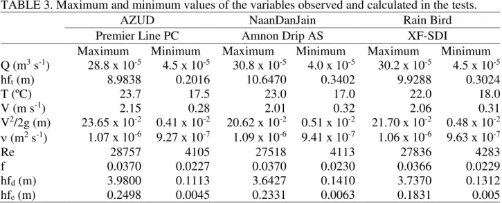
FIGURE 2. Total head loss in the emitter pipe (hft) and local head loss on the emitter (hfe) as a function of flow rate (Q).
The regression coefficient A was 21.8 x 10⁶, 34.6 x 10⁶ and 63.5 x 10⁶ for the Rain Bird XF-SDI, AZUD Premier Line PC and Naan Dan Jain Amnon Drip AC emitter pipes, respectively. In relation to coefficient B it can be observed that the values were 1.80 for the Rain Bird SF-SDI, 1.88 for AZUD Premier Line PC and 1.92 for Naan Dan Jain Amnon Drip AC. These values are close to those observed by Gomes et al. (2010) which obtained coefficients between 1.76 and 1.84 in studies with coaxial emitters.
The local head loss on the emitter presented Pearson correlation coefficients higher than 0.99 in relation to the flow rate, for the three emitter models present in the study (Figures 2.B, 2.D and 2.F), that is, the local head loss can be explained by the flow rate. Zitterell et al. (2014) found similar behavior for this relationship in studies with connectors for trickle irrigation systems. The Naan Dan Jain Amnon Drip AS emitter pipe presented the highest dispersion in the data which according to Rettore Neto et al (2009) can be explained due to the lack of uniformity on the emitter insertion inside the pipe.
The coefficient a (Equation 8) was 4.9 x 10⁵, 20.9 x 10⁵ and 27.7 x 10⁵ for the Rain Bird
XF-SDI, AZUD Premier Line PC and Naan Dan Jain Amnon Drip AS, emitters respectively. Gomes et
al. (2010) found values between 2.2 x 10⁵ and 28.3 x 10⁵. This variation may be due to the type of
studied emitter and the obstruction index caused by its insertion.
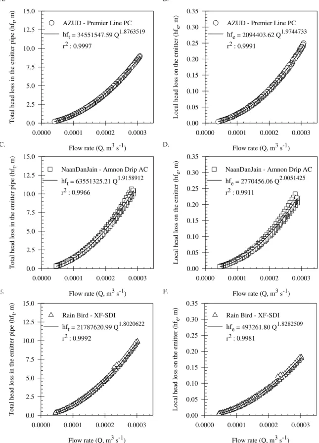
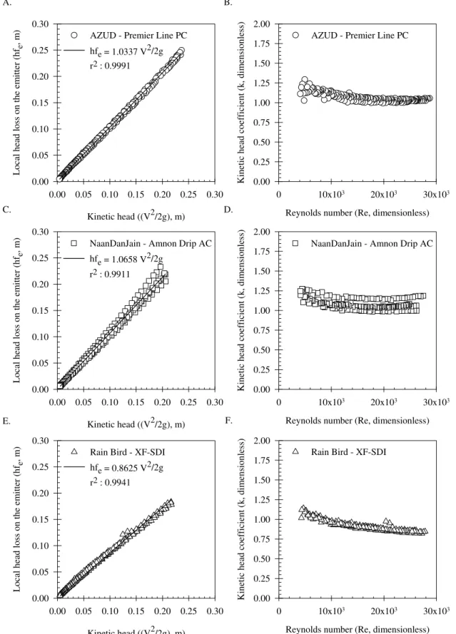
In Figures 3.A, 3.C and 3.E is the relationship between the local head loss on the emitter, and the kinetic head and in Figures 3.B, 3.D and 3.F are the values of kinetic head coefficient for the studied emitters in relation to the Reynolds number.
It can be observed in Figure 3 that the k values are 0.8625, 1.0337 and 1.0658 for the Rain Bird XF-SDI, AZUD Premier Line PC and Naan Dan Jain Amnon Drip AS emitters, respectively.
For all studied emitters the Pearson’s correlation coefficient showed values above 0.99 showing that
the local head loss on the emitter is related to the kinetic head.
In similar studies Rettore Neto et al. (2009) found k values of 0.3378, 0.5295, 0.8445 and 1.2719 with obstruction index of 0.0799, 0.1765, 0.1882 and 0.5649, respectively. Gomes et al. (2010), in studies with coaxial emitter pipes, found k values of 0.1497, 0.3577, 1.1478 and 1.2193 with obstruction indices of 0.0541, 0.1316, 1.1702 and 1.2336. It is clear that the results of the literature demonstrate that k coefficient presents variability according to studied emitter, presenting relation with the obstruction caused by the insertion inside the pipe. This shows the importance of this kind of studies since from the values of k it is inferred the local head loss caused by the emitter in the pipe.
The k coefficient presents dependence on Reynolds number and the geometric characteristics of the obstructing element however in cases where the Reynolds number is high the head loss tends to be dependent only on the emitter obstruction. Thus, in Figures 3.B, 3.D and 3.F present the values of k for the studied emitter pipes in relation to the Reynolds number.
Reynolds number (Re, dimensionless) 0 10x103 20x103 30x103
K ine tic hea d co effici en
t (k, dim
en si on les s) 0.00 0.25 0.50 0.75 1.00 1.25 1.50 1.75 2.00
AZUD - Premier Line PC B.
Kinetic head ((V2/2g), m)
0.00 0.05 0.10 0.15 0.20 0.25 0.30
L oc al head los s on the em itt er (h fe , m ) 0.00 0.05 0.10 0.15 0.20 0.25 0.30
AZUD - Premier Line PC hfe = 1.0337 V2/2g r2 : 0.9991 A.
Kinetic head ((V2/2g), m)
0.00 0.05 0.10 0.15 0.20 0.25 0.30
L oc al head los s on the em itt er (h fe , m ) 0.00 0.05 0.10 0.15 0.20 0.25 0.30
NaanDanJain - Amnon Drip AC hfe = 1.0658 V2/2g
r2 : 0.9911 C.
Reynolds number (Re, dimensionless) 0 10x103 20x103 30x103
K ine tic hea d co effici en
t (k, dim
en si on les s) 0.00 0.25 0.50 0.75 1.00 1.25 1.50 1.75 2.00
NaanDanJain - Amnon Drip AC D.
E.
Kinetic head ((V2/2g), m)
0.00 0.05 0.10 0.15 0.20 0.25 0.30
L oc al head los s on the em itt er (h fe , m ) 0.00 0.05 0.10 0.15 0.20 0.25 0.30
Rain Bird - XF-SDI hfe = 0.8625 V2/2g r2 : 0.9941
F.
Reynolds number (Re, dimensionless) 0 10x103 20x103 30x103
K ine tic hea d co effici en
t (k, dim
en si on les s) 0.00 0.25 0.50 0.75 1.00 1.25 1.50 1.75 2.00
Rain Bird - XF-SDI
FIGURE 3. Local head loss on the emitter (hfe) as a function of kinetic head (V2/2g) and kinetic
head coefficient (k) as a function of Reynolds number (Re).
Obstruction index (OI, dimensionless)
0.0 0.1 0.2 0.3 0.4 0.5 0.6
K
in
etic
h
ea
d
co
eff
ic
ie
nt
(k
, d
imen
sio
nle
ss
)
0.0 0.2 0.4 0.6 0.8 1.0 1.2 1.4 1.6 1.8 2.0
k=1.94 OI0.595 (RETTORE NETO et al., 2009) k=1.66 OI0.413 r2: 0.7502
Prediction Interval (95%) PROVENZANO & PUMO (2004)
PROVENZANO et al. (2005) RETTORE NETO et al. (2009) Experimental Data
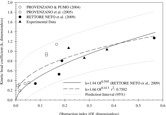
FIGURE 4. Kinetic head coefficient (k) as a function of obstruction index (OI).
In Figure 4 the dashed line corresponds to Equation 2 applied with coefficient equal to 1.66
and coefficient equal to 0.413.
Bagarello et al. (1997) compiling data from Al-Amoud (1995) found for online emitters
coefficients and of 1.68 and 0.645, and Cardoso & Klar (2014) observed of 1.228 and of
0.507. Gomes et al. (2010) in similar studies, but with coaxial emitters obtained 1.387 for and
0.577 for .
However, by performing an analysis with integrated wafer type emitters Rettore Neto et al.
(2009) found values of 1.94 for , and 0.595 for , for domain 1.08 <A/Ar <1.75. The proposed
model by the present study added six new pairs of data, all within the same domain.
All the studies carried out in this sense found similar behavior of the data however, further studies are still necessary in order to allow the best adjustment of the model due to the great variability of the emitters form. It can be stated that physically the regression equation is coherent because when there is a zero obstruction index, that is, no obstruction in the pipe, k coefficient is also zero, with no local head loss.
CONCLUSIONS
The total head loss in the pipe and local head loss on the emitter presented potential relation in function to the flow rate in each studied model of the emitter pipe.
The Rain Bird XF-SDI emitter presented kinetic head coefficient (k) of 0.8625 while the emitters AZUD Premier Line PC and Naan Dan Jain Amnon Drip AS presented values of 1.0337 and 1.0658 respectively.
The kinetic head coefficient can be estimated by the equation (k = 1.66 IO0.413) with r 2 = 0.75
for the OI range from 0.008032 to 0.5649.
REFERENCES
Al-Amoud AI (1995) Significance of Energy Losses Due to Emitter Connections in Trickle Irrigation Lines. Journal of Agricultural Engineering Research 60(1):1-5. DOI:
http://dx.doi.org/10.1006/jaer.1995.1090
Andrade IPS, Carvalho DF, Almeida WS, Silva JBG, Silva LDB(2014) Water requirement and yield of fig trees under different drip irrigation management. Engenharia Agrícola 34(1):17-27. DOI: http://dx.doi.org/10.1590/S0100-69162014000100003
Azevedo Netto JM, Fernandes MF (2015) Manual de Hidráulica. São Paulo, Editora Edgard Blucher. 632p.
Bagarello V, Ferro V, Provenzano G, Pumo D (1997) Evaluating Pressure Losses in Drip-Irrigation Lines. Journal of Irrigation and Drainage Engineering 123(1):1-7. DOI:
http://dx.doi.org/10.1061/(ASCE)0733-9437(1997)123:1(1)
Cardoso GGG, Frizzone JA (2014) Perda de carga localizada em conexão de emissor on-line. Irriga 19(4):537-547.
Cardoso GGG, Klar A (2014) Índice geométrico e perda de carga localizada em conexões de
emissores “online”. Engenharia Agrícola 34(6):1114-1127. DOI: http://dx.doi.org/10.1590/S0100-69162014000600008
Carvalho GC, Coelho E, Silva ASAM, Pamponet AJM (2014) Trickle irrigation: effects on papaya crop. Engenharia Agrícola 34(2):236-243. DOI:
http://dx.doi.org/10.1590/S0100-69162014000200005
Frizzone JA, Freitas PSL, Rezende R, Faria MA (2012) Microirrigação - gotejamento e microaspersão. Maringá, Editora da Universidade Estadual de Maringá.
Geisenhoff LO, Oliveira FC, Biscaro GA, Almeida ACS, Schwerz F (2015) Produtividade do brócolis-de-cabeça sob diferentes sistemas de irrigação. Engenharia Agrícola 35(5):863-874. DOI: http://dx.doi.org/10.1590/1809-4430-Eng.Agric.v35n5p863-874/2015
Gomes AWA, Frizzone JÁ, Rettore Neto O, Miranda JH (2010) Perda de carga localizada em gotejadores integrados em tubos de polietileno. Engenharia Agrícola 30(3):435-446. DOI: http://dx.doi.org/10.1590/S0100-69162010000300008
Paulino J, Folegatti MV, Zolin CA, Sánchez-Román RM, José JV (2011) Situação da agricultura irrigada no Brasil de acordo com o censo agropecuário 2006. Irriga 16(2):163-176.
Provenzano G, Pumo D (2004) Experimental Analysis of Local Pressure Losses for Microirrigation Laterals. Journal of Irrigation and Drainage Engineering 130(4):318-324. DOI:
http://dx.doi.org/10.1061/(ASCE)0733-9437(2004)130:4(318)
Provenzano G, Pumo D, Di Dio PM (2005) Simplified Procedure to Evaluate Head Losses in Drip Irrigation Laterals. Journal of Irrigation and Drainage Engineering 131(6):525-532. DOI:
http://dx.doi.org/10.1061/(ASCE)0733-9437(2005)131:6(525)
Provenzano G, Tarquis AM, Rodriguez-Sinobas L (2013) Soil and irrigation sustainability practices. Agricultural Water Management 120:1-4. DOI:
http://dx.doi.org/10.1016/j.agwat.2013.01.001
Rettore Neto O, Botrel TA, Frizzone JA, Camargo AP (2014) Method for determining friction load loss along elastic pipes. Irrigation Science 32(5):329-339. DOI: http://dx.doi.org/10.1007/s00271-014-0431-7
Rettore Neto O, Frizzone JA, Miranda JH, Botrel TA (2009) Perda de carga localizada em emissores não coaxiais integrados a tubos de polietileno. Engenharia Agrícola 29(1):28-39. DOI: http://dx.doi.org/10.1590/S0100-69162009000100004
Rettore Neto O, Tavares VEQ, Faria LC, Köpp LM, Timm LC (2016) Comportamento das equações de scobey, manning e fairwhipple-hsiao quando utilizadas para estimativa da perda de carga em tubos com comportamento elástico. Revista Brasileira de Agricultura Irrigada 10(1):420-427. DOI: http://dx.doi.org/10.7127/rbai.v10n100343
Uribe RAM, Gava GJC, Saad JCC, Kölln OT (2013) Ratoon sugarcane yield integrated drip-irrigation and nitrogen fertilization. Engenharia Agrícola 33(6):1124-1133. DOI:
http://dx.doi.org/10.1590/S0100-69162013000600005
Zitterell DB, Frizzone JA, Rettore Neto O (2014) Dimensional analysis approach to estimate local load losses in microirrigation connectors. Irrigation Science 32(3):169-179. DOI: