Joana Maria Lopes Delgado
Mestre em Conservação e Restauro
Restoring Medieval
Stained-Glass Transparency:
Use of New Task Specific Luminescent
Ionic Liquids for Corrosion Crusts Removal
Dissertação para obtenção do Grau de Doutor em Conservação e
Restauro do Património
Especialidade em Ciências da Conservação
Orientador:
Márcia Vilarigues, Professor Auxiliar, DRC, FCT/UNL
Co-orientadores:
César A.T. Laia, Investigador Auxiliar, DQ, FCT/UNL
Luís C. Branco, Investigador
Principal, DQ, FCT/UNL
Júri:
Presidente: Prof. Doutor José Paulo Barbosa Mota Arguentes: Prof. Doutor Joost Caen
Prof. Doutor António Jorge Dias Parola
Vogais: Prof. Doutora Maria Helena Figueira Vaz Fernandes Prof. Doutora Isabel Maria Delgado Jana Marrucho Ferreira
Restoring Medieval Stained-Glass Transparency: Use of New Task Specific Luminescent Ionic Liquids for Corrosion Crusts Removal
Copyright © Joana Delgado, Faculdade de Ciências e Tecnologia, Universidade Nova de Lisboa.
A Faculdade de Ciências e Tecnologia da Universidade Nova de Lisboa têm o direito, perpétuo e sem
i
“First God made heaven and earth. The earth was without form and void, and darkness was upon the face of the deep; and the Spirit of God was moving over the face of the waters. And God said, "Let there be light"; and there was light. And God saw that the light was good; and God separated the light from the darkness. God
called the light Day, and the darkness he called Night. And there was evening and there was morning, one day.”
Genesis
“I am too late for the birth of birds but have come just in time for the
opening of a red chocolate bar”
iii
Acknowledgements
This project was held between April 2011 and March 2015, mostly in the campus Faculdade de Ciência e Tecnologia in Caparica, and for some time in Artesis Hogeschool in Antwerp, now University of Antwerp, Belgium, in autumn 2012, and it was financially supported by the Fundação para a Ciência e Tecnologia (SFRH/BD/72808/2010).
I wish to thank first of all, my supervisors, Márcia Vilarigues, César Laia and Luís Branco, who introduced me the idea for this project and were absolutely essential for its materialization and completion, not only for their knowledge and expertise but also for their friendship and constant support. Also a very special thank you to my colleagues; Inês Coutinho and Susana Coentro, who started this journey with me, and were there during all the stages of this project, both of joy and of despair; to Alexandra Rodrigues, Andreia Machado, Hélia Marçal, and later on Amanda Pinto, Fernanda Barroso and Francisca Pulido Valente, who joined a bit later, but for that were not less important. To everybody in Vicarte – in special to the late Solange Muralha, who is deeply missed – and in REQUIMTE, who made it a pleasure to go to work every day. To Ana Maria Martins and Cremilde Cascalheira, who were (and are) always there for us.
I would also like to leave my expression of gratitude for my colleagues in the stained glass conservation studio in the University of Antwerp, who were very welcoming during my stay. And of course a very special word of appreciation to Prof. Dr. Joost Caen, who received me in Antwerp and made me feel as part of the family, but also for his weariless support and advice during and after my stay in Belgium. I also wish to thank Ms. L. Seliger (The Cathedral Studios, Canterbury), Mr. C. Larkum (Sidney Sussex College, Cambridge), and again Prof. Dr. Joost Caen and Dr. Kristel de Vis from the University of Antwerp, for the archaeological samples provided for this study, which without any doubt enriched the discussion tremendously.
For all the time spent helping me analyze the samples in the Scanning Electron Microscope, I must present my sincere acknowledgement to Dr. Daniela Nunes and Dr. Elvira Fortunato, from CENIMAT/I3N; to Maria João Furtado, Filipe Martinho and Dr. Rui Silva, for the help given analyzing the samples in the Optical Microscope available in CENIMAT/I3N. Also a special thank you to Dr. Anabela Raymundo (Instituto Superior de Agronomia), Dr. Luís Cerqueira Alves (Centro de Ciências e Tecnologias Nucleares (C2TN)), Pedro Redol (Monastery of Batalha), and
to the members of my Thesis Advisory Committee, Dr. Isabel Marrucho (Instituto de Tecnologia Química e Biológica) and Lisa Pilosi (The Metropolitan Museum of Art). And of course to Mani Hosseinzadeh, for his precious help and support with the synthesis and characterization of an important part of the ionic liquids used during this project.
v
Resumo
A transparência é uma característica cuja preservação é fundamental num painel de vitral. A passagem da luz é a essência desta forma de arte, sendo, portanto, uma peça crucial da sua intenção original, tanto através do vidro colorido como das pinturas. O vitral medieval é caracterizado por um conteúdo relativamente elevado de óxidos alcalinos e alcalino-terrosos, sobretudo potássio, cálcio e sódio, bem como um reduzido conteúdo de sílica comparativamente ao vidro contemporâneo. Os iões sódicos e potássicos são lixiviados e, uma vez em contacto com a atmosfera, é formada uma camada de sílica-gel (superfície hidratada rica em sílica), seguindo-se consequentemente a formação de uma crosta de corrosão. Esta é composta sobretudo por sais insolúveis, como carbonato (CaCO3), sulfato (CaSO4) e oxalato (CaC2O4) de
cálcio, que são bastante difíceis de remover da superfície do vidro. Os métodos que apresentam maior eficiência na remoção destas crostas – como agentes quelantes (ex.: soluções de EDTA),
ácidos fracos e resinas iónicas – são os mesmos que podem induzir danos ou riscos a longo
prazo na superfície do vidro.
Esta investigação teve como objetivo desenvolver um novo produto – um líquido iónico (LI) – para a remoção da corrosão em vitral medieval, que fosse eficaz e não-nocivo tanto para o vitral como para o utilizador. Para facilitar a remoção completa da corrosão e do material de limpeza (o líquido iónico) após o procedimento, o LI foi composto usando um fluoróforo–líquidoiónico intrinsecamente luminescente. O objetivo foi dotar o LI de uma função dupla: ter um ponto de interação com iões metálicos (neste caso, Ca2+), exibindo ao mesmo tempo fluorescência.
Os efeitos na superfície do vidro modelo de três LIs diferentes, uma solução de EDTA e um ambiente de humidade relativa elevada são descritos e comparados. Foi ainda feita uma comparação entre a eficiência de dois LIs e uma solução de EDTA na remoção de crostas de corrosão, usando fragmentos de vitral arqueológico corroído. Os testes realizados confirmaram a eficácia do líquido iónico na remoção das crostas de corrosão e demonstraram igualmente que não ocorreram quaisquer alterações na superfície do vidro nem na crosta de corrosão remanescente, mesmo quando em contacto direto com os líquidos iónicos durante um longo período de tempo.
vii
Abstract
Transparency is a fundamental feature to preserve on a stained-glass panel. The passage of light is the essence of this art form and, as so, a crucial piece of its original intention, both through the colored glass as through the paintings. Medieval stained-glass is characterized by a relatively high content of alkali and alkali-earth ion oxides, mainly potassium, calcium and sodium, and low contents of silica compared to contemporary glass. These ions are leached, and when in contact with the atmosphere a gel-layer (hydrated silica-rich surface) is formed, and consequently there is the formation of a corrosion crust. This is mainly composed by insoluble salts such as calcium carbonate (CaCO3), sulfate (CaSO4) and oxalate (CaC2O4), which are very difficult to remove
from the glass surface. The methods that present higher efficiency for the removal of those crusts – like chelate agents (e.g. EDTA solutions), weak acids and ionic resins – are the same that may induce damage or long-term risks to the glass surface.
The aim of this research was to develop a new product – an ionic liquid (IL) – for the removal of medieval stained-glass corrosion that is effective and harmless both for the stained-glass and for the user. To assure the complete removal of both corrosion and cleaning material (the ionic liquid) after the procedure, the IL was functionalized using a light emitting marker – intrinsically luminescent ionic liquid. It was our objective to have an IL with a dual function: having a binding site for metal cations (in this case, Ca2+), while exhibiting bright fluorescence.
The effects on the surface of model glass of three different ILs, an EDTA solution and the effect of a high relative humidity (RH) environment are described and compared. A comparison between the efficiency of two ILs and an EDTA solution for the corrosion crusts removal was made using corroded archaeological stained glass samples. The tests performed confirmed the effectiveness of the cleaning material in removing the corrosion crusts, and also demonstrated that there were no detected alterations to the glass surface even when in direct contact with the ionic liquids for a long period of time.
Key words: stained-glass / medieval glass / ionic liquids / glass corrosion / chemical composition / cleaning methods
Published paper: J.M. Delgado, A. Raymundo, M. Vilarigues, L.C. Branco, C.A.T. Laia, Characterization of a Novel Intrinsic Luminescent Room-Temperature Ionic Liquid Based on
[P6,6,6,14][ANS], Chemistry - A European Journal 21 (2015), 726-732.
ix
Symbols and notations
µ-PIXE – micro-Particle Induced X-Ray Emission [ANS] – 8-Anilino-1-naphthalenesulfonic acid
[C2O5MIM] – 1-[2-(2-Methoxyethoxy)ethyl]-3-methylimidazolium
EDTA – ethylenediaminetetraacetic acid FTIR − Fourier Transform Infrared HLLA – High Lime Low Alkali
1H-NMR – Nuclear Magnetic Resonance
IL – Ionic Liquid NIR − Near Infrared
LEDs – Light-Emitting Diode OM – Optical Microscopy
[P6,6,6,14] – Trihexyl(tetradecyl)phosphonium
RH – Relative Humidity
[PyrCOO] - 1-Pyrenecarboxylic RT – Room Temperature
SEM − Scanning Electron Microscopy
SEM-EDS – Scanning Electron Microscopy with Energy Dispersive Scattering T – Temperature
UV− Ultra violet
Vis – Visible
xi
Contents
Introduction 1
Chapter 1 Medieval Stained-Glass 3
1.1 Medieval stained glass windows: paintings in light 3
1.2 Glass production in the Middle-Ages: a short historical introduction 4
1.3 Nature and structure of medieval stained-glass 6
1.4 But what is glass? 9
1.5 Glass corrosion: mechanism of formation 11
1.6 Glass cleaning: State of the art in cleaning technology 15
1.7 Ionic liquids: Introducing a new alternative 16
Chapter 2 Ionic Liquids 17
2.1 What is an ionic liquid? Ionic liquids properties and advantages 17
2.2 Ionic liquids synthesis 19
2.2.1 Synthesis method 19
2.2.2 Equipment and methods 19
2.2.3 Ionic liquids synthesized 20
2.2.4 Why these molecules? 21
2.3 [P6,6,6,14][ANS] – characterization 23
2.3.1 Synthesis of [P6,6,6,14][ANS] 24
2.3.2 Characterization of the IL [P6,6,6,14][ANS] 25
2.3.3 DSC and rheology studies 25
2.3.4 Contact angle 26
2.3.5 NMR studies 27
2.3.6 UV/vis. Absorption Spectroscopy and Emission Spectroscopy
Studies 28
2.4 Characterization of other intrinsically luminescent room temperature ionic liquids
30
2.4.1 [C5O2MIM][ANS] 30
2.4.2 [P6,6,6,14][PyrCOO] 30
xii
Chapter 3 Experimental procedure and techniques 33
3.1 Production of model glass 34
3.2 Corrosion essays: artificial corrosion 35
3.3 Archaeological stained glass samples 35
3.4 Experimental design for the comparison of the ionic liquids effect on model glass
37
3.5 Experimental design for the mid-term effects of the [P6,6,6,14][ANS] IL 38
3.6 Morphologic analysis 39
3.7 Chemical analysis 40
Chapter 4 Corrosion crusts removal: model glass 41
4.1 Samples characterization 41
4.2 Comparison of the effect of ILs and EDTA with high RH on the model glass surface
42
4.3 Mid-term effect of the [P6,6,6,14][ANS] IL on the glass surface 50
4.4 Grisaille: Application of the IL [P6,6,6,14][ANS] on grisaille painted glass 51
4.4.1 Effect of the IL on the grisaille layer 53
4.5 Conclusions 54
Chapter 5 Corrosion crusts removal: archaeological stained-glass 55
5.1 Archaeological stained-glass samples 55
5.2 Comparison of the effect of ILs and EDTA on the glass surface 56 5.3 Effect of the [P6,6,6,14][ANS] IL on the glass surface 60
5.4 Before and after [P6,6,6,14][ANS] 64
5.5 Possible mechanisms and effects: a general comparison between the IL and EDTA
66
5.6 Conclusions 66
Conclusions 67
What comes next? Further suggestions to be developed in the future
67
xiii
Appendix I Complementary data related to Chapter 2 81
i) Nuclear Magnetic Resonance (NMR) of the [P6,6,6,14][ANS],
[C5O2MIM][ANS] and [P6,6,6,14][PyrCOO] ionic liquids
82
ii) [C5O2MIM][ANS] IL complementary data 88
iii) [P6,6,6,14][PyrCOO] IL complementary data 89
Appendix II Complementary data related to Chapter 4 91
i) Optical Microscope images of model glass samples 92
ii) SEM images of model glass samples’ surface 101
Appendix III Complementary data related to Chapter 5 105
i) Archaeological stained-glass fragments: images of the interior and exterior surfaces of the samples.
107
ii) SEM-EDS elementary mapping of archaeological stained glass samples Cant 001, 002, 003, 004, 005, 006, 028, 033 and 034.
113
iii) Cant 042 before and after the application of [P6,6,6,14][ANS] IL 119
xv
List of figures
Figure 1.1 Medieval stained-glass windows at Cathedral of Our Lady of Chartres, France. 3
Figure 1.2 Stained glass Windows in the abside (left) and colors reflected on the wall and on the stained glass windows (right) at Monastery of Santa Maria da Vitória in Batalha, Portugal.
4
Figure 1.3 The Pit of Memnon, depicting glassblowing, from The Travels of Sir John Mandeville (p. 21-22, plate 27). Manuscript dated from 14-15th century (British Library).
5
Figure 1.4 Different phases of the production of a crown glass plate. (a) Plate XI: Wood Glass Making, Operation of Shaping the Tip of the Ball and Blowing it over the Trough, (b) Plate XV: Wood Glass Making, Operation of Heating the Ball to Open it and Make the Pane and Carry it to the Embers Pit, (c) Plate XVI: Wood Glass Making, Operation of Placing the Pane in the Pit and of Refiring it in the Furnace. From
Planches d’Encyclopedie or Dictionnaire raisonée des Arts et Metiers by Diderot and D’Alembert.
6
Figure 1.5 (a) Simplified scheme of the grisaille layer before and after the firing of the glass fragment. (b) Saint Joseph, 16th c., Monastery of Batalha, Portugal and (c) Face detail, 16th c., Convento de Cristo, Tomar, Portugal.
7
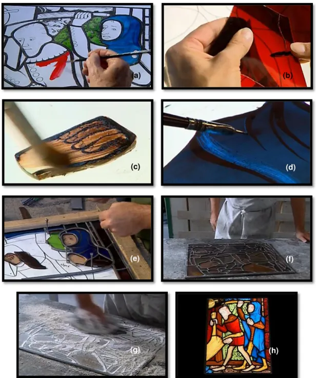
Figure 1.6 Methodology for making a stained glass panel. (a) In the first place, a full size cartoon is made, showing the lead lines around each glass fragment, as well as the colors and details to be painted on the glass; (b) then, the glass – colored or transparent – is cut to size, following the cut-lines from the cartoon; (c) also according to the cartoon, the grisaille painting is made, (d) using different tools and brushes, some of the details being made after the paint is dry. The fragments are fired in a kiln, for the paint – grisaille, yellow silver staining or, later on, enamels – to adhere to the glass surface. (e) By the time all the glass pieces are prepared, they are gathered on the cartoon, over a usually wooden base, and set together by lead came cut to size. (f) After completing this process, each junction is soldered, (g) and cemented on both sides in order to make the panel more resistant and waterproof, being left for a few days to harden. (h) Finally, the panel is complete. These images are stills from the video “Making a stained glass panel”, that can be seen on the Victoria and Albert Museum website.
xvi
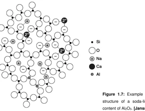
Figure 1.7 Example of a two dimensional structure of a soda-lime glass with a low content of Al2O3.
9
Figure 1.8 Classification of glass used in the production of window glass panes, based on their major composition.
10
Figure 1.9 Types of glass more commonly used in the production of stained glass windows in Europe, from the 13th to the 20th century.
11
Figure 1.10 Glass corrosion mechanism (weathering) starts with a clean and un-corroded surface (a). The formation of a water film occurs, due to the atmospheric conditions, allowing ionic exchange between the ions H+ and H3O+ of water and the alkaline
ions present in glass, which may be reinforced by the presence of acid gases (b). This lixiviation reaction starts slowly, but accelerates overtime; after the formation of a hydrated layer (light blue in the figure), rich in silica and alkaline oxides (c), the glass surface becomes more resistant to the attack of water and the surface pH increases. The crystalline corrosion products (salts) stay in the glass surface after the water evaporates (d).
12
Figure 1.11 SEM-EDS elementary maps of a cross-sectioned archeological sample, presenting Si, O, Ca and Fe elementary maps. 150x magnification.
13
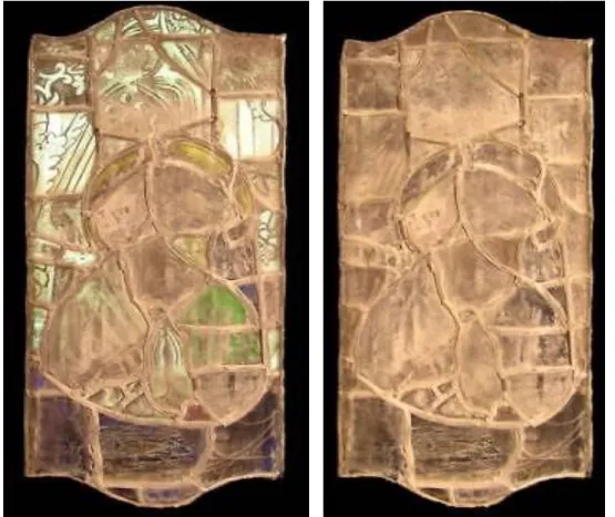
Figure 1.12 Figura aureolada, 15th century stained-glass panel from the Monastery of Batalha, Portugal. Reflected and transmitted light (left) and reflected light (right).
14
Figure 2.1 Functional groups from [ANS] and [PyrCOO] anions molecules where the calcium ions will likely bind.
22
Figure 2.2 Functional groups in the [C5O2MIM] cation molecule more probable to form a link
with calcium ions.
22
Figure 2.3 EDTA molecule with the indication of the areas likely to bind with calcium ions. 22
Figure 2.4 Molecular structures of [ANS] anion and [P6,6,6,14] cation. 23
xvii
Figure 2.6 (a) DSC measurements of [P6,6,6,14][ANS] and (b) viscosity of [P6,6,6,14][ANS] in
heating (circles) and cooling (triangles) cycle. Viscosity values of the heating cycle were fitted with the VTF equation (see text) giving the parameters inserted in the figure.
26
Figure 2.7 Contact angle variation with time of a [P6,6,6,14][ANS] IL drop on a clean glass
surface, and images of this drop at a given time (0, 10, 20, 76 and 118 seconds).
27
Figure 2.8 1H-NMR spectra of pure [P6,6,6,14][ANS] for heating (black lines) and cooling (grey
lines) cycle containing (a) aromatic and (b) aliphatic resonances.
28
Figure 2.9 [P6,6,6,14][ANS] UV/vis absorption and fluorescence spectra (λex=370 nm). 29
Figure 2.10 [P6,6,6,14][ANS] temperature dependence of the fluorescence spectra (λex=370 nm). 29
Figure 2.11 Molecular structures of [C5O2MIM] cation and [ANS] anion. 30
Figure 2.12 Molecular structures of [P6,6,6,14] cation and [PyrCOO] anion. 31
Figure 2.13 [P6,6,6,14][PyrCOO] IL under natural light (transparent yellowish IL) and under UV
light (blue photoluminescence, not as intense as the IL containing [ANS]).
31
Figure 3.1 Stages of production of the glass roundel and final result. 34
Figure 3.2 Experimental design for the experiments comparing the effects of different environment and compounds on model glass samples. Each parameter was tested in 2 samples.
37
Figure 3.3 Scheme of division of an archaeological sample: Section A (control group), section B ([P6,6,6,14][ANS]), section C ([C5O2MIM][ANS]) and section D (EDTA solution).
38
Figure 3.4 Experimental procedure for testing the long term effect of the ionic liquid [P6,6,6,14][ANS] on the glass. (a) One sample was left without any IL, being the control
sample. A drop of IL was deposited on 3 samples of each group. (b) An emission spectra was measured for each sample. (c) The samples were put in a desiccator under vacuum. (d) The emission spectra was measured, (e) and the IL was removed using a swab impregnated with a solution of water:ethanol (1:1/v:v). Its complete removal was always controlled using an UV-light lamp and by the emission spectra.
xviii
Figure 4.1 Comparison between the [P6,6,6,14][ANS] and the [P6,6,6,14][PyrCOO] ILs applied on a
transparent model glass sample after 1 hour and after 1 week, under natural day light and under UV-light. The visual behavior of the other IL, [C5O2MIM][ANS] is
similar to [P6,6,6,14][ANS].
42
Figure 4.2 Optical microscope images of the surface of the model glass samples, with a 5x magnification (a) of a control sample, from group A, (b) a sample from group B, left for 4 weeks in an 88% RH atmosphere, (c) a sample from group C, that was in contact with [P6,6,6,14][ANS] IL for 4 weeks, (d) a sample from group D, that was in
contact with [C5O2MIM][ANS] IL for 4 weeks, (e) a sample from group E, that was
in contact with [P6,6,6,14][PyrCOO] IL for 4 weeks and (f) a sample from group F, that
was in a solution of 3% EDTA + 3% NH4HCO3 in distilled water, pH 8.26, for 1 week.
Optical microscope image with 10 x magnification (g) of the surface of a sample from group B, left for 4 weeks in an 88% RH atmosphere and (h) of a sample from group F, left for 1 day in a solution of 3% EDTA + 3% NH4HCO3 in distilled water,
pH 8.26.
43
Figure 4.3 SEM image of the surface of a model glass sample from group B after being for 7 days in a high RH environment (a) 500x magnification and (b) 1000x magnification. SEM image of the surface of a model glass sample from group F after being for (c) 7 days in an EDTA solution, 500x magnification, (d) and for 28 days in an EDTA solution, 1000x magnification.
45
Figure 4.4 Raman spectra, range 200 to 1200 cm-1, of the model glass samples of all groups. 46
Figure 4.5 Linescan profile (intensities of Ca, Si and K) measured on a cross-sectioned (a) model glass sample from the control group (group A), (b) model glass sample left for 1 week in a high RH atmosphere (group B) and (c) model glass sample immersed in an EDTA solution for 1 week (group F). The red line in the linescan indicates where the glass bulk starts. On the right of each linescan profile, there is the correspondent image of the line where the measure was made, marked as a yellow line with 50 µm.
48
Figure 4.6 Linescan profile (intensities of Ca, Si and K) measured on a cross-sectioned (a) model glass sample after the application of the [P6,6,6,14][ANS] IL for 1 week (group
C), (b) model glass sample after the application of the [C5O2MIM][ANS] IL for 1
week (group D) and (c) model glass sample after the application of the [P6,6,6,14][PyrCOO] IL for 1 week (group E). The red line in the linescan indicates
where the glass bulk starts. On the right of each linescan profile, there is the correspondent image of the line where the measure was made, marked as a yellow line with 50 µm.
xix
Figure 4.7 Emission spectra of the IL (a) 4 weeks after the application of the IL on a model glass sample and (b) after the removal of the IL.
50
Figure 4.8 SEM image of the surface of an un-corroded sample – Group A –(a) before and (b) after the application of [P6,6,6,14][ANS] IL for 12 weeks, 200x magnification. SEM
image of the surface of an artificially corroded sample from Group B (c) before and (d) after the application of [P6,6,6,14][ANS] IL for 12 weeks, 100x magnification.
51
Figure 4.9 Optical microscope images of the surface of the model glass samples, with a 5x magnification (a) of a grisaille painted sample, after the removal of the [P6,6,6,14][ANS] IL using a dry swab, bright field filter, (b) and the same sample under
UV-light filter (c) after the removal of the IL using a swab impregnated with a water:ethanol (1:1) solution once, and (d) after another passage with a swab impregnated in the same solution.
52
Figure 4.10 Optical microscope images of the surface of the model glass samples, with a 5x magnification of grisaille painted model glass samples that were in contact with [P6,6,6,14][ANS] IL for: (a) 15 minutes, (b) 1 day, (c) 1 week and (d) 28 days, all after
the removal of the IL using a swab impregnated with a water:ethanol (1:1).
53
Figure 5.1 Scheme of division of an archaeological sample: Section A (control group), section B ([P6,6,6,14][ANS]), section C ([C5O2MIM][ANS]) and section D (EDTA solution).
56
Figure 5.2 SEM images and EDS maps of a cross-sectioned archaeological sample (a) before and (b) after the application of the [P6,6,6,14][ANS] IL, (c) after the application of the
[C5O2MIM][ANS] IL and (d) after the application of the and EDTA solution. The
corresponding EDS maps for Si, O, Ca and Fe are presented. In these images it is possible to see a layer very rich in Si (hydrated layer), and another above very rich in Ca (corrosion layer), as well as the Fe (corresponding to the grisaille layer).
57
Figure 5.3 FTIR spectra of archeological samples, before and after the application of the IL and EDTA, with the indication of the most representative peaks.
58
Figure 5.4 pH of the surface of samples Cant 028, Cant 033 and Cant 034, before and after the application of [P6,6,6,14][ANS] IL, [C5O2MIM][ANS] IL and an EDTA solution. For
every sample, three measurements were made, and the average is presented in the chart above, with the respective value indicated. The standard deviation is <0.07 for all samples except Cant 028 (a) (0.19) and Cant 033 (c) (0.14).
xx
Figure 5.5 Archaeological sample (a) before and (b) after cleaning tests using [P6,6,6,14][ANS]
IL, under natural light, (c) and after the cleaning tests, under 365 nm UV-light.
60
Figure 5.6 (a) Emission spectra of the IL (i) 4 weeks after the application of the IL on a model glass sample and (ii) after the removal of the IL. (b) Emission spectra of the IL (i) when it is applied on an archaeological sample, (ii) after 4 weeks, (iii) after the removal of the IL (iv) and after being photodegraded using a Solar lamp for 1 minute and (v) 10 minutes.
61
Figure 5.7 Optical microscope image of the surface of an archaeological sample (a) before and (b) after cleaning tests using [P6,6,6,14][ANS] IL. 5x magnification, dark field filter.
SEM image of the surface of an archaeological sample (c) before (d) and after the application of [P6,6,6,14][ANS] IL for 12 weeks, 200x magnification.
61
Figure 5.8 FTIR spectra of the corrosion present in the surface of an archaeological sample (a) before and (b) after the application of the [P6,6,6,14][ANS] IL.
62
Figure 5.9 SEM-EDS elementary maps of a cross-sectioned archeological sample (a) before and (b) after the application of the IL [P6,6,6,14][ANS]. 100x magnification.
63
Figure 5.10 Archaeological stained glass fragment before and after the application of [P6,6,6,14][ANS] IL, with reflected light (a,b) and transmitted light (c,d).
64
Figure 5.11 Archaeological stained glass fragment before and after the application of [P6,6,6,14][ANS] IL, with reflected light (a,b) and transmitted light (c,d).
xxi
List of tables
Table 2.1 Detailed information about the cations used. 20
Table 2.2 Detailed information about the anions used. 21
Table 2.3 UV/vis spectroscopy measurements of [P6,6,6,14][ANS]. 28
Table 3.1 Composition of the glass produced. 34
Table 3.2 Composition of the archaeological stained-glass samples (% mol and % weight). 36 Table 4.1 Identification of the Raman bands associated with the components of the Si–O
stretching and bending modes.
1
Introduction
The idea for the use of ionic liquids to remove glass corrosion emerged and was developed in a previous project at the Conservation and Restoration Department, Vicarte and REQUIMTE, all at FCT-UNL, starting from 2009. The project had very promising results, but one of the problems that came upon was the difficulty in detecting the presence of the ionic liquid on the glass surface after the cleaning procedure. Having this problem in mind, a new alternative was suggested: the use of a luminescent marker to allow an easy detection of the presence of the ionic liquid. This idea was developed and the results of the synthesis and application of novel intrinsically luminescent ionic liquids for corrosion crusts removal are here presented.
One of the most important, but also delicate, phases in the conservation practice is the cleaning process, no matter what is the material. It is also a controversial topic, which makes it important to understand and debate. Corrosion crusts are a result of the deterioration of original material, being a part of the history of the object. However, these crusts can also block the passage of light, one of the most important elements in a stained glass panel. In such cases the corrosion crusts become an obstacle to the visualization of the object in its entire splendor. As corrosion has a protective role, it is very important to have into consideration that any cleaning procedure should remove the corrosion deposits only as far as necessary to improve the transparency, without damaging the hydrated glass surface underneath as the gel-layer protects the glass beneath. There is a balance that needs to be obtained between the preservation of the original material and the preservation of the original essence of the stained-glass panel.
From these considerations, the first chapter of this document is devoted to understand and give a general idea about the importance of stained-glass as an artistic and religious expression in the middle-ages, being this understanding fundamental to comprehend the work of art as a whole. To this follows a description of what is glass as a material, how it was produced in the middle-ages, as well as a succinct introduction of the glass corrosion mechanisms. Finally, an approach on the state of the art of glass corrosion removal from stained-glass and an introduction to the new solution proposed: luminescent ionic liquids.
In the second chapter, a short introduction to what is an ionic liquid is made, followed by the description of the synthesis method of the luminescent ionic liquids that will be tested as well as its characterization. A more in depth study and characterization was carried in the case of the trihexyl(tetradecyl)phosphonium 8-Anilino-1-naphthalenesulfonic acid ionic liquid ([P6,6,6,14][ANS] IL),
with results published in 2015 in Chemistry - A European Journal (DOI: 10.1002/chem. 201402534, ref. [Delgado 2015]).
2
On the fourth and fifth chapters, the application of the ionic liquids is described. The cleaning tests and consequent effects of the ILs tested on the surface of model glass samples will be developed in the fourth chapter, being these results compared to the effect of an aqueous solution of ethylenediaminetetraacetic acid (EDTA) and ammonium bicarbonate (NH4HCO3) and a high relative
humidity (RH) environment. Preliminary tests were also carried out in model glass samples painted with grisaille (which consists in a mixture of grounded glass, iron or copper oxide and a binder, that was
applied to the glass surface and then fired; a more detailed introduction to grisaille can be found in Chapter 1), being the results presented in the end of this forth chapter.
3
Chapter 1
Medieval Stained-Glass
In this chapter, the material aspect of the medieval stained-glass will be developed, starting by understanding what is glass and how was the stained-glass produced in the middle-ages. Then, an insight on the glass corrosion process, as it is important to understand the nature of glass corrosion before discussing new solutions for its removal. Finally, an approach on the state of the art of glass corrosion removal from stained-glass is made, as well as an introduction to the new solution proposed and developed during this project: luminescent ionic liquids.
1.1 – Medieval stained glass windows: paintings in light
In most cultures, the concept of light and clarity holds a positive connotation, associated to the birth of each new day. There are several references on the Bible relating God to light, categorizing it as something mystical and divine, which enlightens the believers. As Saint John refers in the New
Testament, Christ said “I am the light that came into the world, that whosoever believeth on me should
not abide in darkness” (John, 12:46).
“One cannot conceive the sense and grandiosity of a great gothic cathedral without the light and color atmosphere that its stained-glass windows create”. [Alcaide 1969] No other artistic support incorporates, like glass, this fundamental element of the artistic work – light –, neither works with it in such an intimate way. In figures 1.1 and 1.2, the mystical atmosphere of the different buildings, provided by the stained glass windows, is evident.
4
Glass technology itself is very fond of fire, and like this full of symbolism. The creation of stained-glass windows consisted, in the Middle Ages, as a way to express Faith, being its primal objective to ornate the house of God. Through the glass and the colorful lights that resulted from the application of the stained-glass panels, that filtered the entrance of light by projecting colors on the inside of the church – similar to precious stones –, there was created an atmosphere propitious to a mystical adoration, suggesting a semblance to the divine (figure 1.2). [Aubert 1983; Caviness 1985, pp. 548-554; Worringer 1992, Raguin 2003] Pierre de Roissy, chancellor of the chapter of Chartres, said that the windows that are in church and through which it transmits light from the Sun means the Holy Scriptures, which protect us from evil and illuminate us all (c.1200). The poetics and aesthetics of light can be extended to the precious stones, translucent material that reflected colored lights, bringing a theological reflection that can be associated with the heavenly Jerusalem. [Duby 1993] However, the high prices and the difficulties inherent to its execution made it particularly rare in Portugal, when compared to the expression it had in the rest of Europe, from the Middle-Ages until nowadays. [Custódio 2000, Redol 2000]
Figure 1.2: Stained glass Windows in the abside (left) and colors reflected on the wall and on the stained glass windows (right) at Monastery of Santa Maria da Vitória in Batalha, Portugal (Joana Delgado ©).
1.2 – Glass production in the Middle-Ages: a short historical introduction
According to Jorge Custódio, the diffusion of the use of glass in houses and buildings is a medieval
5
On the first half of the 12th century Theophilus Presbyter, a Benedictin monk, wrote De diversis artibus,
one of the most famous manuscripts describing the manufacturing and artistic techniques used to produce a stained-glass panel (amongst other techniques used in various applied arts). [Barroca 2002, pp. 288-289] The raw materials used in the production of glass were sand, ashes of plants (wood from trees such as beech – potash glass –, or from marine plants – soda glass) and colored by adding specific metallic oxides. It is important to mention that many times the color in the glass was granted involuntarily by impurities present in the raw materials. [Redol 2003] In figure 1.3, an illustration from a manuscript dated from the 15th century, the several phases of the production of glass objects are portrayed, from
collecting the raw materials, the glass blowing and manufacture, to the inspection of the final pieces. [Raguin 2003]
Should you intend to make glass, first cut a quantity of beech-wood logs and dry them.
Then burn them together in a clean spot, and, carefully collecting the ashes, take care that
you mix no earth with them. (…)
Then take two parts of the ashes (…) and a third part of sand, carefully purged of earth and
from the stones which you may have brought from the water, mix them in a clean place.
Theophilus, De diversis artibus The second book, Chapter I and Chapter IV [Presbyter 1979]
6
There were two main methods to produce glass sheets, crown and cylinder, both glass blowing methods. With the blowpipe, a portion of fused glass is collected from the furnace, being immediately blown to form a hollow globe (figure 1.4 a). [Redol 2003] For the crown glass, this globe is transferred from the blowpipe to a punty and then reheated and flattened by spinning out the glass globe into a flat disk (figure 1.4 b and c). [Redol 2003] With this method, the resulting glass sheet has a round shape, with a variable thickness from the irregularly shaped center – called bullseye – to the edge, allowing a lower variety of dimensions and shapes when cutting the glass pieces, when compared to cylinder glass. [Redol 2003] As for the cylinder glass the globe is elongated into a cylinder, which is then cut lengthwise and separated from the blowpipe. After being cut, the cylinder is reheated to allow it to open and flatten into a glass sheet, later on smoothed with a piece of wood. This method allows obtaining much larger glass panes, with a more homogeneous surface. In both production techniques, the glass sheets need to be reheated and left to cool down slowly, to reduce tensions and avoid cracking. [Redol 2003, Navarro 2003]
Figure 1.4: Different phases of the production of a crown glass plate. (a) Plate XI: Wood Glass Making, Operation of Shaping the Tip of the Ball and Blowing it over the Trough, (b) Plate XV: Wood Glass Making, Operation of Heating the Ball to Open it and Make the Pane and Carry it to the Embers Pit, (c) Plate XVI: Wood Glass Making, Operation of Placing the Pane in the Pit and of Refiring it in the Furnace. From Planches d’Encyclopedie or Dictionnaire raisonée des Arts et Metiersby Diderot and D’Alembert[d’Ambert 2002].
1.3 – Nature and structure of medieval stained-glass
7
glass facing the interior of the building. It is essentially a mixture of a flux (glass and lead oxide or lead rich glass) with metal powders of metal oxides (iron or copper), a mixture that is usually dark in color (brown or black) and highly pigmented. [Debitus 1991, Redol 2003, Schalm 2003] Then, the powder is mixed with a small amount of water and some binding compound – Arabic gum, for example – in order to obtain a paste that can be used to paint the glass. [Debitus 1991, Redol 2003, Schalm 2003] After dried, the fragments are fired at temperatures between 600 and 750o C in order to obtain the vitrification
of the painting material, resulting in a connection between the glass surface and the flux (glass and lead oxide or lead rich glass), with the pigments in suspension [Debitus 1991, Redol 2003, Schalm 2003] (scheme presented in figure 1.5 (a)).
So ultimately, the final result is a lead reach glass, with particles of metals oxide (mainly iron or copper) in suspension in the matrix. [Debitus 1991] The ratio between the flux and the pigment may determine the adherence of the grisaille to the glass surface underneath [Veritá 1996, Schalm 2003], being the deterioration of the glass or of the flux one of the factors that can lead to the detachment of the paint layers. The decoration of the surface consisted mainly in dark trace lines combined with shades, used to depict faces and garments, architectural elements and landscapes, for example [Redol 2003]. The color and level of detail were variable, as in the examples presented in figure 1.5.
Figure 1.5: (a) Simplified scheme of the grisaille layer before and after the firing of the glass fragment (adapted from O. Schalm et al. [Schalm 2003]). (b) Saint Joseph, 16th c., Monastery of Batalha, Portugal (Paula Fernandes©) and (c) Face detail, 16th c., Convento de Cristo, Tomar, Portugal (Joana Delgado©).
8
Figure 1.6: Methodology for making a stained glass panel. (a) In the first place, a full size cartoon is made, showing the lead lines around each glass fragment, as well as the colors and details to be painted on the glass; (b) then, the glass – colored or transparent – is cut to size, following the cut-lines from the cartoon; (c) also according to the cartoon, the grisaille painting is made, (d) using different tools and brushes, some of the details being made after the paint is dry. The fragments are fired in a kiln, for the paint – grisaille, yellow silver staining or, later on, enamels – to adhere to the glass surface. (e) By the time all the glass pieces are prepared, they are gathered on the cartoon, over a usually wooden base, and set together by lead came cut to size. (f) After completing this process, each junction is soldered, (g) and cemented on both sides in order to make the panel more resistant and waterproof, being left for a few days to harden. (h) Finally, the panel is complete. [Redol, 2003] These images are stills from the video “Making a stained glass panel”, that can be seen on the Victoria and Albert Museum website
[http://www.vam.ac.uk/content/videos/m/video-making-a-stained-glass-panel/], V&A©. (h) (g)
(f) (e)
(d) (c)
9
1.4 – But what is glass?James E. Shelby defines glass as “an amorphous solid completely lacking in long range, periodic atomic
structure, and exhibiting a region of glass transformation behavior”. [Shelby 2005, p.3] Here, glass is an amorphous inorganic material that can be cooled below its super-cooling temperature and re-heated above it, without this causing the appearance of crystalline phases [Janssens 2013, p.8].
In the context of medieval stained glass, the main component of glass is silica, the network former (figure 1.7). The fusion temperature of pure silica is too high to allow a workable glass, and the energy needed to achieve such temperatures would be too expensive. As so, it is necessary to add a flux and a stabilizer
– network modifiers, such as alkali and earth alkali compounds – (figure 1.7), that have a strong effect on the alteration of the glass final structure and properties. [Navarro 2003, Janssens 2013] The flux, usually a soda or potash ash traditionally made from burning marine plants, trees or ferns, helps to lower the fusion temperature; while the stabilizer – calcium oxide being one of the most common, in the form of limestone – will prevent the dissolution of the glass, as well as the formation of crystals, by avoiding phase separation/crystallization, conveying a better durability. [Navarro 2003, Shelby 2005]
Figure 1.7: Example of a two dimensional structure of a soda-lime glass with a low content of Al2O3. [Janssens 2013, p. 9]
However, if a glass has a higher amount of network modifiers, its stability is compromised; the higher the content of silica in a glass matrix, the higher the chemical stability and durability of the glass. [Navarro 2003] And from the 15th up to the mid-16th century, in Europe, the most commonly used glass
in stained-glass windows was potash glass [Caen 2009]1, which contains a high content of Na
2O (see
figure 1.8).
10
In figure 1.8, a scheme is presented with a stratification of glass types according to composition. This was adapted from a O. Schalm et al. publication, being based on several published classifications2
[Schalm 2010]. The first criteria to consider is the amount of PbO in the glass, if being superior to 15 wt%, the glass can be classified as lead glass. If it is inferior to 15 wt%, the wt% of Na2O will be the next
parameter to take into consideration, followed by the ratio of K2O/Na2O, depending on which the glass
will be classified as: soda glass, mixed-alcali glass, potash glass or high lime low alkali (HLLA) glass.
Figure 1.8: Classification of glass used in the production of window glass panes, based on their major composition
[adapted from O. Schalm et al. 2010] Note: HLLA stands for High Lime Low Alkali glass.
In figure 1.9, the evolution of the most commonly used types of glassin the production of stained glass windows in Europe is presented. Potash and HLLA glass were the most common types of glass from the 15th to mid-18th century [Caen 2009], both types containing less than 6 wt% of Na2O in its
composition, and a wt% of CaO varying from 16 to 22 for potash glass and from 21 to 28 for HLLA glass [Schalm 2010].
2 For more detailed information about the compositions and classifications used, some examples of publications
referred in O. Schalm et al. are:
- Gratuze B., 1994, Le verre : les éléments de réponses que peuvent proposer les méthodes de caractérisation physico-chimiques aux problématiques archéologiques posées par ce materiau, Revue dʼArchéometrie, 18 (1994) 75-87.
- Müller W., Torge M., Adam K., Ratio of CaO/K2O > 2 as evidence of a special Rhenish type of medieval stained glass, Glasstechnische Berichte Glass Science and Technology, 67 (2) (1994) 45-48.
11
Figure 1.9: Types of glass more commonly used in the production of stained glass windows in Europe, from the 13th to the 20th century (image adapted from J. Caen, The Production of stained glass in the county of Flanders and
the Duchy of Brabant from the XVth to the XVIIIth centuries: materials and techniques. Brepols, Antwerpen, 2009. Copyright © 2009 Brepols [Caen 2009]).
1.5 – Glass corrosion: mechanism of formation
The medieval stained-glass is composed by a high concentration of alkaline and alkaline-earth ions – mainly potassium, calcium and sodium – and low contents of silica compared with contemporary glass, being the chemical composition of medieval glass one of the main causes for its deterioration. [Newton 1989, Vilarigues 2004, De Bardi 2013, De Bardi 2013i] The other main cause is the presence of water,
being temperature fluctuations, polluting agents and microorganism’s effects other important factors.
[Redol 2003, Vilarigues 2009]
12
Figure 1.10: (a) Glass corrosion mechanism (weathering) starts with a clean and un-corroded surface. (b) The formation of a water film occurs, due to the atmospheric conditions, allowing ionic exchange between the ions H+
and H3O+ of water and the alkaline ions present in glass, which may be reinforced by the presence of acid gases. (c) This lixiviation reaction starts slowly, but accelerates overtime; after the formation of a hydrated layer (light blue in the figure), rich in silica and alkaline oxides, (d) the glass surface becomes more resistant to the attack of water and the surface pH increases. The crystalline corrosion products (salts) stay in the glass surface after the water evaporates (adapted with permission from M. Melcher et al., Degradation of Glass Artifacts: Application of Modern Surface Analytical Techniques, Accounts of Chemical Research (2010), Copyright © 2010 American Chemical Society [Melcher 2010]).
In the presence of water, corrosion of glass will occur with the formation of a hydrated layer and lixiviation of ions of Ca2+ and K+. The presence of pollutant agents, such as CO2 and SO2, will accelerate this
process, and corrosion crusts are formed at the surface. These crusts are composed by insoluble salts, such as calcium carbonate (CaCO3), calcium sulphate (CaSO4) and calcium oxalate (CaC2O4), and
others, which are very difficult to remove from the glass surfaces. [Newton 1989, Clark 1992, Carmona 2006, Cailleteau 2008, Vilarigues 2009] As can be seen in figure 1.10, where we can observe a simplified scheme of a proposed glass corrosion mechanism (weathering), in the presence of water, an ionic exchange between the ions H+ and H3O+ and the alkaline and alkaline-earth ions present in glass
13
loss of paint layers – such as grisaille –, and the loss of the glass material itself. [Romich 2000] The hydrated layer formed in the surface presents mechanical properties different from the original glass matrix, and with the flotation of relative humidity and temperature, tensions between both occur, which may lead to the formation of micro fissures that can develop through the entire glass surface. [Carmona 2006] In some cases there is also the formation of syngenite (K2Ca(SO4)2•H2O) and arcanite (K2SO4) [Tournié 2008, Machado 2010, Machado 2011].
In the figure below (figure 1.11), elementary maps of a cross-sectioned archaeological sample present a good example of the final stage of the corrosion process explained in figure 1.10. The hydrated layer, rich in Si and O, is clearly visible below the grisaille painting layer, rich in Fe, and right above this one there is a calcium corrosion crust, very noticeable as well.3
Figure 1.11: SEM-EDS elementary maps of a cross-sectioned archeological sample, presenting Si, O, Ca and Fe elementary maps. 150x magnification.
These corrosion crusts that cover the surface of the glass can be perceived as a protective layer [Romich 2003, Murcia-Mascarós 2008, Abd-Allah 2013], but, at the same time, are blocking the passage of light, one of the most important elements for a stained-glass panel. In figure 1.12 an example of a heavily corroded panel is presented. Having this into consideration, as well as the fact that the corrosion crust is, in essence, original material deteriorated and, as so, part of the history of the object itself, there is a balance that needs to be obtained between the preservation of the original material and
14
the preservation of the original essence of the stained-glass panel. It is very important to remember that any cleaning procedure should remove the corrosion deposits only as far as necessary to improve the transparency, without damaging the hydrated glass surface underneath as the gel-layer protects the glass beneath. A thin residual layer should be left on the surface, rather than removing the crust down to the bulk glass, which would trigger further degradation. Special attention is necessary when cleaning painted areas, since the loss of paint would irreversibly damage the artistic integrity of the stained-glass. [Romich 2000, Romich 2003, Murcia-Mascarós 2008, Abd-Allah 2013]
Figure 1.12: Figura aureolada, 15th century stained-glass panel from the Monastery of Batalha, Portugal. Exterior side, reflected and transmitted light (left) and reflected light (right) (Joana Delgado ©). Dimensions: 70 x 31.2 cm2.
The stained-glass panel presented in the figure above (1.12) is one of several from the collection of 15th
15
1.6 – Glass cleaning: State of the art in cleaning technology
One of the most important, but also delicate, phases in the conservation practice is the cleaning process, no matter what is the material [Murcia-Mascarós 2008]. It is essential to maintain or increase the chemical stability of the treated object. It is very important to remember that any cleaning procedure should remove the corrosion deposits only as far as necessary to improve the transparency, without damaging the hydrated glass surface underneath. A thin residual layer should be left on the surface, rather than removing the crust down to the bulk glass, which would trigger further degradation. The gel-layer must not be damaged, as it can protect the glass beneath. [Romich 2000] Special attention is necessary when cleaning painted areas, since the loss of paint would irreversibly damage the artistic integrity of the stained-glass. As so, the objective is to reduce or stabilize the weathering process and to improve the readability of the object.
A variety of mechanical and chemical methods is currently used in restoration practice. The mechanical methods include the scalpel, bristle brushes and glass-fiber brushes, among others, and the chemical methods go from the use of water, usually in combination with ethanol (water:ethanol, 1:1 [v/v]), to organic solutions. However, those that present a higher efficiency in removing or diminishing the corrosion crusts are the same that may induce damage or long-term risks to the glass surface. These are the application of chelant agents, such as ethylenediaminetetraacetic acid (EDTA), weak acids and ionic resins. [Romich 2000, Altavilla 2008, Abd-Allah 2013] Depending on the conditions of the glass surface, these products may cause irreversible damage. The consequences of the application are also difficult to control, and it is complicated to evaluate if all the remains of product are completely removed after the treatment, presenting an aggravated risk to the glass surface. [Romich 2000]
16
1.7 – Ionic liquids: Introducing a new alternativeThe development of cleaning methods that are effective and harmless for the work of art but also less harmful to health and the environment are major concerns of conservators/restorers. Therefore, the possibility of replacing volatile and toxic organic solvents by ionic liquids (ILs) could contribute to safer procedures.
A more detailed description on ILs and its characteristics will be given in Chapter 2. However, these compounds possess interesting characteristics, such as the possibility to tune their solubility and viscosity depending on the polarity and functional groups of cation/anion combinations, which make them attractive for many different applications [Branco 2002]. Preliminary studies showed some efficiency of ILs for the gentle cleaning of the corrosion products from the surface of the glass, without damage, through control of its viscosity and solubility properties. [Machado 2010]
New approaches provided by modern chemistry were explored during this project, such as the use of ILs as an alternative non-toxic solvent. ILs are defined as organic salts formed by a combination of an organic cation and organic or inorganic anion with a melting point below 100ºC. [Johnson 2007] Recently, patents describing the use of ionic liquids for surface cleaning were published [Patent A1 2006, Patent A2 2006, Patent 2010] Of special importance is patent WO2010040917A1 [Patent 2010] that describes the use of a protic imidazolium room temperature ionic liquid (RTIL) for the cleaning of surfaces such as metals, ceramics and glass contaminated with oil, grease or soil.
Organic aromatic compounds often exhibit fluorescence emission when irradiated with UV light. Some of those compounds are sensitive to the environment, responding to effects such as temperature or the presence of metal cations such as calcium. Examples of several fluorescent compounds (e.g., coumarins, rhodamines and fluoresceins molecules) are described in the literature for the sequestration of calcium cations in biomedical applications [Silva 1997]. Some of these molecules allow the possibility to have negative charge (anionic), and therefore they may be combined with organic cations that are known to give rise to ILs. These intrinsic luminescent ILs are a new type of luminescent material that was described recently [Tang 2008], but to best of our knowledge there are still no published examples of luminescent ionic liquids able to dissolve inorganic salts such as CaCO3.
17
Chapter 2
Ionic Liquids
As explained before, the intention of this project is to develop a new task specific luminescent ionic liquid for the removal of insoluble stained glass corrosion crusts. Being these crusts mainly composed by calcium salts, enabling the solubilization of the corrosion crusts soluble and consequently an easy removal from of easily removed from the glass surface. That is also what happens with EDTA, a strong chelating agent, which will not only bind with the calcium ions present in the corrosion crusts, but also with the calcium present in the glass surface, as a composing element of this material (see Chapter 1.5). So being, the selected molecules must have a weaker chelating power than EDTA, in order to have a milder effect on corrosion crusts, and especially on the glass surface. It is also important to have intrinsically luminescent ionic liquids allowing the detection of their presence after the cleaning procedure. The viscosity is also of extreme importance, as compound with a low viscosity is more difficult to situate and control during the treatment. Another important requested characteristic is related to the solubility of ionic liquid (IL) in water or in a less toxic organic solvent (e.g. ethanol), making the removal of the ILs from the glass surface after the treatment harmless for the conservator, for the object and for the environment
In this chapter, a brief introduction about ionic liquid topic including their peculiar properties and potential applications will be given, in order to put into context and justify why these class of compounds have been chosen for the specific purpose of this project. Then, a general description of the synthetic methodology and characterization of the intrinsically luminescent ILs, in particular: trihexyltetradecylphosphonium 1-anilino-naphtalene 8-sulfonate, [P6,6,6,14][ANS],
1-[2-(2-Methoxyethoxy)ethyl]-3-methylimidazolium 1-anilino-naphtalene 8-sulfonate, [C5O2MIM][ANS], and
trihexyltetradecylphosphonium 1-pyrene carboxylate, [P6,6,6,14][PyrCOO], will be presented. These ILs
were considered the ones with the most promising characteristics – good viscosity, chemical stability and bright fluorescence – in order to perform the tests in the glass samples, described in Chapters 4 and 5.
2.1 – What is an ionic liquid? Ionic liquids properties and advantages
In the past few years, ionic liquids have been largely studied, and their large range of possible applications was widely explored. Ionic liquids are composed by an organic cation and an organic or
inorganic anion, they are liquid at temperatures under 100 ºC and present some peculiar and tunable
18
Recently, novel generations of ILs were developed, in which a cation or anion is chosen in order to obtain ILs with specific physical, chemical or biological functions, usually called task specific ionic liquids. [Kulkarni 2007,Wasserscheid 2007, Branco 2009, Freemantle 2009, Branco 2011, Branco 2011i, Ferraz 2011, Hallett 2011, Kokorin 2011, Branco 2013]
The first known IL was reported by Walden in 1914 and was an ethylammonium nitrate [Walden 1914]. The main composition of the first generation of ILs was cations like dialkylimidazolium and alkylpyridinium, and toxic and non-biodegradable anions such as metal halides (e.g. chloroaluminate). [Tavares 2013] This first generation was mostly focused on substituting organic solvents, toxic and volatile, by an alternative solvent to be used in synthesis and catalysis operations. [Tavares 2013] The first room temperature IL (RTIL) was reported in 1982 by Wilkes et al. [Wilkes 1982, Faridbod 2011], and since then a big variety of ILs containing various cations and anions has been synthesized.
Consequently, a second generation of ILs appeared, composed by more biocompatible cations and anions [Bogel-Lukasik 2015] and presenting lower melting points and other interesting tunable properties that lead to the widespread of their use in many different fields, facing a significant boost in
the 1990’s. This second generation still presents a level of toxicity comparable to aromatic solvents, which is a disadvantage. [Tavares 2013, Bogel-Lukasik 2015]
A last generation of ILs, the third, can be defined by the use of biocompatible cations and anions, which allowed the exploration of the possibilities of its use for pharmaceutical and biological purposes [Sekhon 2011, Marrucho 2014]. This is based in more hydrophobic and stable anions, also characterized by its biodegradability and low toxicity. [Tavares 2013]
ILs are mostly used as solvents, but its applications are vast, spreading through different fiels, from electrochemistry to engineering, analytic techniques to biological uses, and the field is growing exponentially, partially thanks to a positively close cooperation between academia and industry. [Wilkes 2002, Pechkova 2008]
Within this framework, intrinsically luminescent ionic liquids were also developed, where usually the anion is the luminescent molecule. These ILs represent a new approach for the development of photochemically active materials. The common method would be to dissolve photochromic [Pina 2007, Pina 2011] or photoluminescent compounds [Karmakar 2002, Hu 2006] in neat ILs. However, some groups have described the possible combination of specific molecules such as metal complexes [Tang 2008, Gago 2013, Pereira 2013], fluorescein [Rodrigues 2013] and anthracene derivatives [Babu 2013] with appropriate organic cations giving intrinsic luminescent ILs. Potentially these ILs may have applications in, e.g., foldable light emitting devices, solar cells or fluorescence sensors. [Gago 2013]
19
2.2 – Ionic liquids synthesis2.2.1 – Synthesis method
The method used to synthesize the ILs was a traditional ionic exchange method, as illustrated and described below. In general, the selected cation was dissolved in an appropriate solvent, such as dichloromethane (or another solvent that can be efficient to solubilize the starting materials and simplify the final purification of the product) in slight defect (1:1.1 mol) in relation to anion, in order to force the reaction to occur. Then, this solution is added to a room temperature (RT) solution of the anion using the same solvent and left stirring during at least 24 hours at room temperature. Then, the solution is purified by simple filtration of insoluble inorganic salts (e.g. ammonia chloride or sodium chloride) using the same organic solvent. After this purification, the solvent is removed in rotary evaporator and the final product is dried in vacuum for 24 hours.
2.2.2 – Equipment and methods
Nuclear Magnetic Resonance (NMR) spectra were done on a Bruker AMX 400 instrument operating at 400.13 MHz (1H) and 100.61 MHz (13C). Temperature effects were monitored submitting the sample
to successive heating steps up to 85ºC followed by similar stepwise cooling. Temperatures quoted were those presented in the spectrometer temperature control unit.
Fourier Transform InfraRed (FTIR) spectra were recorded on a Buker Tensor 27, using NaCl cells for the deposition of RTIL as a stable film.
Elemental Analysis (C, H, N) analysis was obtained on a Thermofinnigan Flash EA 1112 Series
instrument by the Laboratório de Análises at REQUIMTE, FCT/UNL.
Differential Scanning Calorimetry (DSC) analysis was carried out using a Setaram, model DSC 131 with a refrigerated cooling system. The temperature range was from -100 to 100 ºC and the scanning
rates were 10 ºC/min. The resolution is ±0.2 µW. The sample is continuously purged with 50 ml/min
nitrogen. About 5-10mg of salt was crimped in an aluminium standard sample pan with lid. Glass transition temperature (Tg) were determinate in the second heating.
20
laser from Quantel, using the second harmonic (λexc=355 nm, laser pulse half-width equal to 6 ns). An optical cut-off filter (570 nm) for the emitted light was used in order to avoid scattering light contamination. Fluorescence lifetimes (τ) were measured via time correlated single photon counting technique (TCSPC) using a home-built equipment. The samples were excited at 373 nm using a nanoled (IBH). The electronic start pulses were shaped in a constant fraction discriminator (Canberra 2126) and directed to a time to amplitude converter (TAC, Canberra 2145). Emission wavelength was selected by a monochromator (Oriel 77250) imaged in a fast photomultiplier (9814B Electron Tubes Inc.), the PM signal was shaped as before and delayed before entering the TAC as stop pulses. The analogue TAC signals were digitized (ADC, ND582) and stored in multichannel analyzer installed in a PC. Temperature control was performed with a water bath connected to the spectrophotometer, with an approximate accuracy of ±1 °C.
2.2.3 – Ionic liquids synthesized
A wide range of non-luminescent ionic liquids was synthesized during the course of this project. The tables 2.1 and 2.2 include information about the cations and anions used in the synthesis of the ILs that were tested in the course of this project, being the results presented in chapters 4 and 5. The prices of each compound are also presented, because this was one of the factors taken into consideration, as having a relatively cheap alternative was also one of the goals.
Table 2.1: Detailed information about the cations used.
Cation, commercial name and molecular formula
Chemical structure (without Cl-)
Brand, reference and price (in 25th January
2016)
[P6,6,6,14][Cl]
[CH3(CH2)5]3P(CH2)13CH3Cl Trihexyltetradecylphosphonium
chloride
MW= 519.31 g/mol
Cytec Sigma-Aldrich
CAS number 258864-54-9
5 g / 16.5 €
[C5O2MIM][Cl] or
[C5O2MIM] [BF4]
C25H29N3O5
1-[2-(2-Methoxyethoxy)ethyl]-3-methylimidazolium
MW= 220.70 g/mol (Cl) MW= 272.05 g/mol (BF4)
Solchemar