Abstract
In this paper, distribution of peeling stress in two types of adhe-sively-bonded joints is investigated. The joints are a single strap and a stiffened joint. Theses joints are under uniform tensile load and materials are assumed orthotropic. Layers can be identical or different in mechanical or geometrical properties. A two-dimensional elasticity theory that includes the complete stress-strain and the complete stress-strain-displacement relations for adhesive and adherends is used in this analysis. The displacement is as-sumed to be linear in the adhesive layer. A set of differential equa-tions was derived and solved by using appropriate boundary con-ditions. Results revealed that the peak peeling stress developed within the adhesive layer is a function of geometrical and mechan-ical properties. FEM solution is used as the second method to verify the analytical results. A good agreement is observed be-tween analytical and FEM solutions.
Keywords
Stress distribution, adhesive joint, strap joint, stiffened joint, finite element, peeling stress
Theoretical Analysis of Stress Distribution
in Bonded Single Strap and Stiffened Joints
1 INTRODUCTION
Adhesively-bonded joints are widely used due to their several advantages over the other methods. Wider contact region in adhesively-bonded joints is the cause of more uniform stress distribution. In the same weight, bonded joints show more strength than the other common methods such as threaded connections, welding and riveting. Adhesively-bonded joints are stronger in fatigue, failure and they are corrosion resistant. Composite materials that are widely used these days are weak in local stresses so it is critical to use mechanical joints due to their stress concentration. Adhesively-bonding acts over areas not a single point so they are the best choice in Adhesively-bonding different composite layers. There are several joint designs for bonding the layers such as single-lap, double-lap, single strap, stepped-lap, stiffened, scarf butt, etc.
Behnam Ghoddous a
a Young Researchers and Elite Club,
Ahvaz branch, Islamic Azad University, Ahvaz, Iran, [email protected]
http://dx.doi.org/10.1590/1679-78253147
distribu-repairing of damaged parts. In a double-strap joint with an embedded patch, patch was embedded into the adherents for structural requirements. In addition, to increase the strength of the joint, two adhesives were used to bond the adherends. They used nonlinear finite element method to predict the failure loads to assist with the geometric design and to identify effective ratios of sizes to max-imize joint strength. Shishesaz and Bavi (2012) had an investigation on void and debond effects in a double lap joint. For symmetric debonds and voids with relative lengths of 0.8, the same effects were observed. In a comparison for defects between single-lap and double-lap joints they reported that the increase in stress is higher in single-lap joint than in double lap joints. Karachalios et al. (2013), studied the effect of defects on the strength of a single-lap joint with various adherend and adhesive materials. Two different types of adhesive were studied with different degrees of ductility since the stress distribution along the overlap depends on the adhesive’s capacity to deform plas-tically. Steel adherends were used from low strength and high ductility to high strength. Rectangu-lar and circuRectangu-lar defects located in the middle of the overlap were studied. The artificial defect con-sists of a thin film of Teflon placed in the middle of the overlap, thus creating a disbond of the re-quired size. When a toughened structural adhesive is used with a high-strength steel, there is an almost linear decrease in joint strength as the defect area increases. In the case of the brittle adhe-sive, the reduction in strength, as the defect size increases, is not proportional for small defect sizes, indicating that the end of the joint becomes more important due to local strains exceeding limiting values. Ghoddous and shishehsaz (2016), investigated an adhesively-bonded stepped-lap joint suffer-ing from a void within its adhesive layer. They used classical elasticity theory to determine shear stress field in the separated sections of the adhesive layer along the overlap length. They declared that the stepped-lap joint performed better in stress distribution with void rather than single-lap and double-lap joint.
In this paper, peeling and shear stress distribution in the middle of the adhesive layer and peel-ing stress field between adhesive and adherends in a speel-ingle strap joint and a stiffened joint are stud-ied. The adherends are orthotropic and it is assumed that the adherends have bending deformation beside longitudinal displacement. The adhesive layer shows shear defamation. Longitudinal and transversal displacement equations are considered as a linear function in the thickness direction. Shear stress is assumed to be constant across the adhesive layer and the layers can be either similar or dissimilar in geometry or mechanical properties. The analytical solution can satisfy the boundary conditions completely. Theoretical results are verified by FEM results which obtained from ANSYS software.
2 ANALYTICAL SOLUTION
2.1 Stiffened Joint
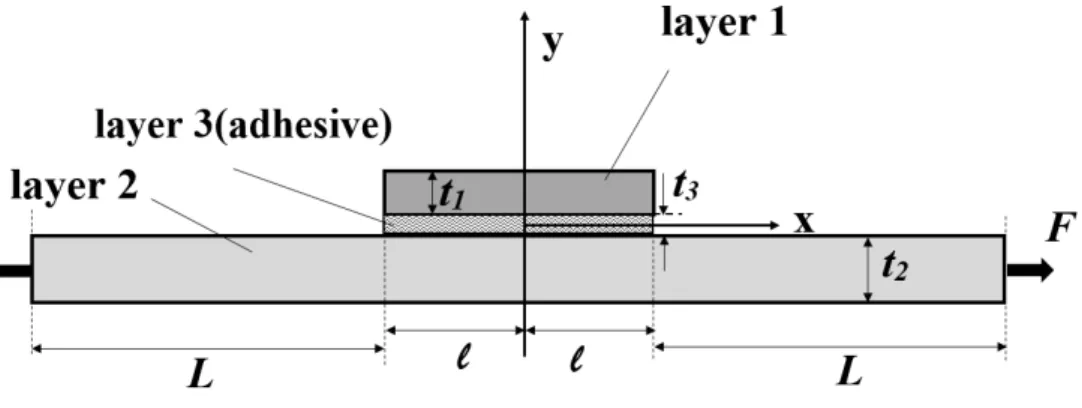
The model of the joint can be reduced to a two-dimensional model because the load is uniform and shear and normal stresses are not varied in the z direction. Figure 1 shows a model of the joint.
Figure 1: stiffened lap joint configuration.
ix
E
andE
iy are the elastic modulus of the layers in x and y directions .
ixz and
izx are Pois-son’s ratio.f
1 andf
2 are internal forces in the unit of width in the layers 1 and 2 respectively. F isthe external tensile force applied uniformly to the joint in x direction. The following assumptions are
assumed in this analysis. The mode of this analysis is plain stress. It means that the stresses in z
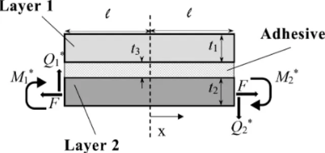
direction are constant. Shear stress is assumed to be constant through the adhesive layer. Differen-tial equation of transversal and longitudinal displacements in the adhesive is assumed to be a linear function. Axial force is ignored in the adhesive layer due to the small Young’s modulus of adhesive rather than the Young’s modulus of adherends. Cylindrical bending theory is used to calculate de-formations in the adhesive and adherends. Free body diagrams for an infinitesimal element in the overlap region are shown in Figure 2.
1,
2 are shear stresses and
1y,
2y are peel stresses inlayer 1 and 2.
From the equilibrium in x and y direction: 1
3
0
df
dx
(1-a)2
3
0
df
dx
(1-b)1
3uy
0
dQ
dx
(2)2
3ly
0
dQ
3
3
(
3uy 3ly) 0
d
t
dx
(4)Figure 2: Free-body stress equilibrium diagram.
From the moment equilibrium in layer 1 and 2:
1 1
1 3
2
0
dM
t
Q
dx
(5-a)2 2
2 3
2
0
dM
t
Q
dx
(5-b)3 3
( )
x
m
is the shear stress in adhesive. 3u y
, 3l y
are peel stress between adhesive and layer 1 and 2 respectively. The relationship between force and moment in the layers with axial stress in x direction is:2
6
(2
1)
ix
f
it
iM
i it
i
(6)0
y
it
i,
i
y t
i i( 1,2)
i
(7)From the elasticity theory and equilibrium:
0
(
1,2,3)
ix i
i
i
x
y
(8-a)0
( 1,2,3)
iy i
i
i
y
x
The subscripts 1, 2 and 3 denote the upper adherend, lower adherend and adhesive, respective-ly. Substituting Equations 8-a, 8-b into 6 and using the Equations 1-a, 1-b, 2, 3 and 4:
2 2
1 3
(3
12 ) 6 (
1Q
1 1 1)
t
1
(9-a)2 2
2 3
(3
24
21) 6 (
Q
2 2 2)
t
2
(9-b)Where,
1
0
10
(10-a)2
1
20
(10-b)Substituting Equations 9-a, 9-b into 8-a, 8-b:
3 2 3 2
3
1y 1
(
1 1)
3uy( 2
13 )
1d
t
dx
(11-a)3 2 3 2
3
2y 2
(
22
2 2)
3ly(2
23
21)
d
t
dx
(11-b)3
3y 3uy 3
(
30.5)
d
t
dx
(11-c)Where,
3 3 3
0.5
(
y t
) 0.5
(12)Constants of integrations for the Equations 11-a and 11-b are determined by Equation 10 and for the Equation 11-c, Equation 13 is used.
3
0.5
3y 3uy
(13)picking
3
0
, and using the Equation 11-c lead to calculate peeling stress in the middle of adhesive layer
m . using Equation 11-c and picking
30.5 and
3
0.5
:3
3
2
u m
y m
t
d
dx
(14-a)3 3ly m m
2
t
d
dx
(14-b)Relationship between shear stress and shear modulus is shown in Equation 15.
(
1,2,3)
i ixy
i
i
G
Stress-strain relationship for orthotropic materials is depicted by Equation 16.
0
0
(
1,2)
0
0
ixz iy ix i i ix ixixz iy iy
iy iy i i ixy i i
E
E
D
D
E
E
i
D
D
G
(16)1
i ixz izx
D
(17)Peeling stress and strain is derived from Equation 16 as follow:
( 1,2)
iy i ixz iy
iy ix
i i i
E
v
E
i
D
y
D
(18)
i
iy i ixz iy ix ix iy
i
v
A
E
E
y
(19)Where,
2 2
(
1, 2)
i i
ix iy ixz iy
D
A
i
E E
E
(20)For transversal displacement of the layer 1, by substituting Equations 6 and 11-a into Equation 19 and then integrating by
1:
1
1 1 1 1 0 1 1 1 1 1 1
4 3 4
3
3 1 1 1
1 1 1 1 1 3 1
2 1
1 1 1 1 1 1 1
1
4
3
2
6
(
)
u xz y x x y
u
u x y
xz x
v
v
A t
E
E
d
d
v
A t E
t
dx
M
A E
f
t
(21) 1uv
is the transversal displacement for top surface of the layer 1. Transversal displacement between adhesive and layer 1 is derived by continuity of displacement and using Equation 21 as follow:3 3 1
1 1
(
11)
1 1 1 112
2
1 1 1 1u y
l u x xz y
d
t
v
v
v
A t E
A E f
dx
(22)4 3 4 3
3 1 1 1
1 1 1 1 1 1 3 1
2 1
1 1 1 1 1 1 1
1
1
1
4
3 12
2
2
6
(
1)
(
)
u
l x y
xz y
d
v
v
A t E
t
dx
M
A E
f
t
(23)Similarly for the layer 2:
4 3 2 4
3
3 2 2 2 1
2 2 2 2 2 2 3 2 2
2 2
2 2 2 2 2 2 2
2
2
4
3
2
2
6
(
)
l
u x y
xz y
d
v
v
A t E
t
dx
M
A E
f
t
(24)From continuity of displacements:
3 1 3 1
3 2 3 2
,
,
u l u l
l u l u
v
v
u
u
v
v
u
u
(25)For longitudinal displacements:
( 1,2,3)
i i i iu
v
i
y
x
(26)By substituting Equation 23 into Equation 26, using Equation 15 and integrating by
1:1
1
u
1u
1l
(27)
3 2 1
1 1 1 1 1 1 1 1 1 1 1
1
2 5 4 5 4
3
2 3 1 1 1 1 1 1
1 1 1 2 1
3 2
3 1 1 1 1 1 1 1 1 1 1
1
1
( )
(
1)
(2
3
1)
1
7
20 12 12 20
10
4
2 20
1
(
1)
l
l xz y
u y x
xz y xz y
dv
u
u
t
Q
A E
dx
G
d
d
A t E
t
dx
dx
t
A E
A E
G
(28)
2 2
2 2 2 0 2 2 2 2
3 2 2
2 2 2 2 2 2 2 2 2
2
2 5 4 3 5 4 2
3
2 3 2 2 2 2 2 2
2 2 2 2 2
3 2
3 2 2 2 2 2 2 2 2
2
( )
( ( )
)
1
(2
3 )
20
6
6
10
4
2
1
2
u
u
u xz y
l y x
xz y xz
v
u
u
t d
x
dv
u
Q
A E
t
G
dx
d
d
A t E
t
dx
dx
t
A E
A
G
2 2
E
y
2
(29)
2u
u
is the displacement of top surface of layer 2 (bonded surface).1 2
0
(
0.5)
i ix i i i
M
t d
(30)1 0
i ix i i
f
t d
(31)Using Equations 11 and 16:
3 2 3 2
3 1
1 1 1 1 1 3 1 1
1 1
1
(
)
u( 2
3 )
x xz y
y
d
u
t
dx
A E
x
(32-a)3 2 3 2
3 2
2 2 2 2 2 2 3 2 2
2 2
1
(
2
)
l(2
3
1)
x xz y
y
d
u
t
dx
A E
x
(32-b)By substituting Equations 32 into Equations 30 and 31 and using Equations 1 to 4:
3
2 2
3 3
1 1 1 1
1 1 1
2 3
1 2
3 1 1 1
1 1 1
1 1 1 3
2 3
1 1 1
11
6
1
210
5
10
12
13
12
1
35
5
2
l x
xz y
u
y u y
x
xz y y
d
d
d v
A E t
A E
dx
dx
G
dx
d
M A E
A E t
A E
dx
t
G
t
(33-a)2 2 3
2 2 2 2 3 3
2 2 2
2 3
2 2
3 2 2 2
2 2 2
2 2 2 3
2 3
2 2 2
11
6
1
210
5
10
12
13
12
1
35
5
2
u x
xz y
l
y l y
x
xz y y
d v
A E t
d
d
A E
dx
dx
G
dx
d
M A E
A E t
A E
dx
t
G
t
(33-b)3 3
1 1 1 1 1 1 1
3 3
1 1 1 1 1
3
1 1
2 2
3 1 1 1 1 1 1
1 1 1
3
2 2
1 1
4
2
105
15
15
6
6
11
1
210
5
10
xz y y
l x
u
y xz y u y
x
y
t
A E
f A E
d
d
du
t A E
t
dx
dx
G
dx
t
d
A E
M A E
t A E
dx
G
t
(34-a) 3 32 2 2 2 2 2 2
2 2 2 2 3 2 3
3
2 2
2 2
3 2 2 2 2 2 2
2 2 2
3
2 2
2 2
4
2
105
15
15
6
6
11
1
210
5
10
xz y y
u x
l
y xz y l y
x
y
t
A E
f A E
du
t A E
d
t
d
dx
dx
G
dx
t
d
A E
M A E
t A E
dx
G
t
(34-b)Differential equations of transversal and longitudinal displacement are assumed to be linear in the
3 direction.3
0.5(
2u 1l)
3(
2u 1l)
u
u
u
u
u
(35-a)3
0.5(
2u 1l)
3(
2u 1l)
v
v
v
v
v
(35-b)Where
v
3 is transversal displacement andu
3 is longitudinal displacement in adhesive. Shear stress in the middle line of adhesive thickness
m is obtained by substituting Equations 35 inEqua-tion 26 and derivaEqua-tion:
2 1 2 1
3 3 3
3
(
) 1
(
0)
2
u l u l
m
u
u
dv
dv
G
t
dx
dx
(36)Neglecting axial load in adhesive layer (
3x), peeling stress in the middle layer of adhesive
mis derived in Equation 37.
3 3
3 3 3 2 1
3 3
(
0)
(
)
m y u l
v
E
E
v
v
y
t
(37)Derivation of Equations 36 and 37, substituting Equations 33 and 34 and using 14-a and 14-b lead to elimination of 3u
y
and 3l y
.2 1 1
3 2 1 1
1 2 7 8 3 1 3 1
1
2
2 2 2 2
2 3 2 3 2
6
(
)
(
)
(
)
6
6
(
)
6
y m m yA E
t f
D
D
D
t
t M
t
A E
t f
1 1 1 2 2 2
3 2
7 8 4 5 3 3
1 2
12
12
(
)
(
)
y ym m
M A E
M A E
D
D
D
t
t
(38-b)Where D=d/dx and
i( 1,2,...,11)
i
is a simplifier coefficient and is related to geometricaland mechanical configurations of the adhesive and adherends.
Derivation of Equations 38-a and 38-b and substitution of derivation moment
M
i and forcef
iby using Equations 1 and 5 create nonhomogeneous differential Equations 39-a and 39-b
1 3 1 1 1
4 2 3
1 2 10 7 8 3
1
2 3 2 2 2 3 2
6
(
)
(
)
6
y
m m
y
t
t Q A E
D
D
D
D
t
t
t Q A E
t
(39-a)1 1 1 2 2 2
3 3
7 8 11 4 5 3 3
1 2
12
12
(
)
(
)
y ym m
Q A E
Q A E
D
D
D
D
t
t
(39-b)Derivation of Equations 39-a and 39-b and using Equations 2, 3 and 14 to eliminate derivation of shear force
dQ
idx
create two fifth order linear homogeneous differential Equations.5 3 4 2
1 2 3 7 8 9
(
D
D
D
)
m
(
D
D
)
m
0
(40-a)5 3 4 2
7 8 9 4 5 6
(
D
D
D
)
m
(
D
D
)
m
0
(40-b)Shear stress distribution and peel stress distribution can be found by solution of Equations 40-a and 40-b.
In this type of joint layer 2 is under tensile load and layer 1 isn’t subjected. Thus,
0
l
m l
dx
(41)For the free surfaces of adhesive in its ends:
0
m x l
(42)Figure 3 shows edge loads in adhesive region.
For the boundary conditions of loads shown in figure 3:
1 1 1 3
0,
2 1,
2 1,
2x
l
M
Q
f
M
M Q
Q f
F
(43-a)2 2
,
2 2,
2,
1 1 1 30
Figure 3: A section of adhesive and its edge loads in the stiffened joint.
Substituting Equations 43-a and 43-b into Equations 38-a, 38-b, 39-a and 39-b determines the other essential boundary conditions to solve Equations 40-a and 40-b. the edges load can be deter-mined by calculating deformations in different parts of the joint. As the joint is symmetric, a half of it is shown in figure 4.
Figure 4: Deflections in different section of stiffened joint.
1 1cosh 1 1 2sinh 1 1
w C
x C
x (44-a)2 3cosh 2 2 4sinh 2 2
w C
x C
x
(44-b)To determine the set of C coefficients four boundary conditions is needed.
1 0 : 1 0
x w (45-a)
1 1, 2 0: 1 2
x L x w w (45-b)
1 2
1 1 2
1 2
,
0 :
dw
dw
x
L x
dx
dx
(45-c)2
2
:
0
dw
x
l
dx
As the joint symmetric:
1
2
* * 1
1 2 2 2
1
u x L
d w
M
M
D
dx
(46)2.2 Single Strap Joint
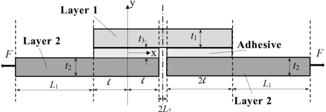
Single strap joint is consisted of three composite layer with orthotropic properties. It can be either symmetric or asymmetric in geometry and property. Figure 5 shows a two-dimensional model of a single strap joint.
Figure 5: Single strap joint configuration.
Analytical solution of the joint is similar with the solution of previous joint and derived differ-ential Equations expressed in Equations 40-a and 40-b are valid here. Figure 6 shows edge loads in three different sections. Set of Equations 47 expressed deflection function of adhesive and adherends.
2
1 1
1 2
1 1 1
(
)
u u
d w
M
F
w
dx
D
D
(47-a)2
2 2
2 1 2
2
2 2 2
1 (
)
2
u u
d w
M
F
w
t
t
dx
D
D
(47-b)2
3 3 2
3 2
3 3u 3u
2
d w
M
F
t
w
dx
D
D
(47-c)General solution of Equations 47-a to 47-c is derived in set of Equation 48.
1 1cosh 1 1 2sinh 1 1
w C
x C
x (48-a)2 3cosh 2 2 4sinh 2 2 ( 1 2) 2
w C
x C
x t t (48-b)3 5cosh 3 3 6sinh 3 3
w C
x C
x
(48-c)To determine the set of C coefficients six boundary conditions is needed.
1 0 : 1 0
x w (49-a)
1 1, 3 0: 1 3
x L x w w (49-b)
3 1
1 1 3
1 3
,
0 :
dw
dw
x
L x
dx
dx
(49-c)3 2
2 3
2 3
0,
2 :
dw
dw
x
x
l
dx
dx
(49-d)2 0, 3 2 : 2 3
x x l w w (49-e)
2 2 2
2
:
dw
0
x
L
dx
(49-f)Finally, determination of edge loads is done by using Equations 50-a to 50-d
1 1
2
* 1
1 1 2
1
u x L
d w
M
D
dx
(50-a)2
2
* 2
2 2 2 0
2
u x
d w
M
D
dx
(50-b)1 1
3
* 1
1 1u 3 x L
d w
Q
D
dx
2
3
* 2
2 2 3 0
2
u x
d w
Q
D
dx
(50-d)3 FINITE ELEMENT MODEL
The finite element method was used as the second method to verify analytical solution. A two-dimensional model was created by ANSYS. Element PLANE 183 was chosen to mesh the geometry model. This high order eight-node element has two degrees of freedom at each node, (translation in the nodal x and y directions). External tensile load (0.6kN/mm) was applied to the right edge of Layer 2 and the left edge of this layer was constrained both in x and y directions. The adhesive layer is Epoxy and adherends are made of aluminum with their nominal mechanical properties ex-pressed by table 1. The geometry of joint is reported by table 2. Figure 7 shows the meshed FEM model.
E(GPa) ν
Adherends 69 0.3
Adhesive 3 0.35
Table 1: Mechanical properties of the adherend and adhesive.
Figure 7: FEM model of a stiffened joint.
t3 0.2
t1 2
t2 2
l 10
4 RESULTS AND DISCUSSION
Derived analytical equations showed that geometry, material properties and load condition affect shear and peel stress distribution along the joint length. These effects are studied in this part beside comparisons of solution methods employed in the article.
4.1 Stiffened Joint
Peeling and shear stress in a stiffened joint are shown in Figure 8 and Figure 9. Results of numeri-cal and analytinumeri-cal method for stress distribution can be compared in the Figures.
Figure 8: Peeling stress
0
m
p
distribution in overlap region of the stiffened joint.Figure 8 indicates that peak peeling stress
0
m
p
is at both ends of overlap length. This type ofstress is in its minimum value at the middle point of the joint where
x
0
.Peak shear stress0
m
occurs at a point near two ends of overlap length as Figure 9 shows. Figures 10 and 11 depict peel-ing stress distribution between the adhesive and layer 1, 3uy
and the adhesive and layer 2, 3l y
,respectively. Comparing Figure 10 and 11 reveals that peak peeling stress between layer 2 and ad-hesive is much more than peak peeling stress between the adad-hesive layer and layer 1. Values of 3u
y
and 3l y
are zero except their severe gradient at 12% of both overlap length ends. Except for the end regions of overlap length, FEM results shows good agreement with analytical results. Simplifi-cations due to the applied assumptions may have a role in the incompatibility of results in the end regions.Figure 10: peeling stress distribution between the adhesive and layer 1 in the stiffened joint.
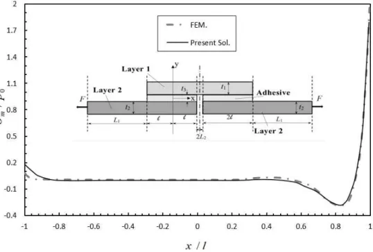
4.2 Single Strap Joint
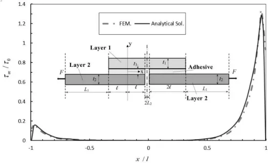
Shear stress distribution in the adhesive layer (in its middle of thickness) along the overlap is depicted in Figure 13.
Figure 11: peeling stress distribution between the adhesive and layer 2 in the stiffened joint.
Figure 13: shear stress distribution in the middle of adhesive layer in stiffened join.
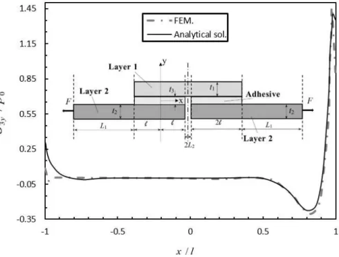
Shear stress distribution in Figure 13 declares peak of shear stress is near the internal edge of layer 2. Its value is about zero in along the 75% of overlap length. Shear stress at the left edge of adhesive is about 12% of the peak. Results show that two methods of solution are in good agree-ment but FEM is more conservative in estimating of maximum stress. Figures 14 and 15 depict peeling stress distribution between the adhesive and layer 1, 3u
y
and the adhesive and layer 2,3ly
, respectively.It is observed that peeling stress that is tolerated by the joint between the upper adherend and adhesive is about zero along the overlap except the middle region of joint at the internal edges. In this region the peak stress is occurred. The stress field shown in Figure 15 has a similar shape to depicted field of Figure 14 but it is clear that the peak peeling stress between the upper adherend and adhesive is greater. Peak peeling stress between the lower adherend and adhesive is about 56% of its corresponding value for peeling stress between the upper adherend and adhesive. FEM meth-od agreed analytical solution. In edges some incompatibility are observed and they are considered to be the result of stress concentration.
Figure 15: peeling stress distribution between lower adherend and adhesive.
5 CONCLUSION
external edges in the stiffened joint and internal edges in the single strap joint were observed as critical locations in designs.
References
Chun, H. (1999). Stress analysis of adhesively-bonded single-lap joints, J. of Composite Structure 47: 673-678. Ghoddous, B., Shishesaz, M. (2016). Investigation on Void Effect on Shear Stress Field in Bonded Stepped-Lap Joint, J. of Latin American Journal of Solids and Structures 13: 331-343.
Karachalios, E.F., Adams, R.D., Da Silva, L.F.M. (2013). Strength of single lap joints with artificial defects, J. of Adhesion and adhesive 45: 69-76.
Li, G., Sullivan, L.P. (1999). Thring RW. Nonlinear finite element analysis of stress and strain distributions across the adhesive thickness in composite single-lap joints, J. of Comp. Struct. 46: 395–403.
Lou, Q., Tong, L. (2008). Analytical solutions for adhesive composite joints considering large deflection and trans-verse shear deformation in adherends, J. of International Journal of Solids and Structures 45: 5914-35.
NASA-CR-112235 NASA Langley contract report. Hart-Smith, L.J., (1973). Adhesive-bonded single-lap joints. Ojalvo, U., Eidinoff, H.L. (1978). Bond thickness effects upon stresses in single-lap adhesive joints, J. of American Institute of Aeronautics and Astronautics Journal 16: 204-211.
Sawa, T., Liu, J., Nakano, K., Tanaka, J. (2000). A two-dimensional stress analysis of single-lap adhesive joints of dissimilar adherends subjected to tensile loads, J. of Adhesion Science and Technology 14: 43-66.
Shahin, K., Taheri, F. (2009). Deformations in adhesively bonded joints on elastic foundations, J. of Composite Structure 90: 130–140.
Shishesaz, M., Bavi, N. (2012). Shear stress distribution in adhesive layers of a double-lap joint with void or bond separation, J. of Adhesion science and technology: 1-29.
Temiz, S., Adin, H., Sulu, I.Y. (2015). Behaviour of Bi-Adhesive in double-strap joint with embedded patch subject-ed to bending, J. of Theoretical and Applisubject-ed Mechanics 45: 83–96.