Abstract
In this paper, an adhesively-bonded stepped-lap joint suffering from a void within its adhesive layer is investigated. The void separates the layer into two sections. The joint is under tensile load and materials are isotropic and assumed to behave as linear elastic. Classical elasticity theory is used to determine shear stress distribution in the separated sections of adhesive layer along the overlap length. A set of differential equations was derived and solved by using appropriate boundary conditions. Finite element solution was used as the second method to verify the obtained results by analytical method. A two-dimensional model was creat-ed in ANSYS and meshcreat-ed by PLANE elements. A good agreement was observed between two methods of solutions. Results revealed that the stepped-lap joint performed better in stress distribution with a void rather than single-lap and double-lap joints.
Keywords
Shear stress, adhesive joint, stepped-lap, finite element, void.
Investigation on Void Effect on Shear Stress
Field in Bonded Stepped-Lap Joint
1 INTRODUCTION
Adhesively-bonded joints are widely used due to their several advantages over the other common methods. The most important property is controllable stress distribution compared to high stress concentration regions in most mechanically joints. There are several joint designs for bonding parts. The Stepped-lap joint is one of the most common and efficient designs. Stepped lap joint design is used in the F/A-18, a twin-engine supersonic combat jet, to attach wings to the fuselage. There is no moment to be applied to parts due to the inline loading path.
Considerable researches in the field of bonded joints have been conducted on single lap joints, Volkersen (1938), Goland and Reissner (1944), Hart-Smith (1973), Chuan (1999), double lap joints, Smith (1973), Chuan (1999), Da Silva et al. (2009), scarf joints and stepped-lap joints, Hart-Smith (1973), Mortnsen and Thomsen (1997), Ichikawa et al. (2008), Sawa et al. (2010), Kimiaeifar et al. (2013). Effects of defects have been analyzed in some works, Kan and Ratwani (1983), Ros-settos and Zang (1993), Lang and Mallic (1999), Chadegani and Batra (2011), Bavi (2011),
Behnam Ghoddous a Mohamad Shishehsaz b
a Department of mechanical engineering,
Islamic Azad University, Ahvaz Branch, Ahvaz, Iran, [email protected] b Department of mechanical engineering,
Shahid Chamran University, Ahvaz, Iran, [email protected]
http://dx.doi.org/10.1590/1679-78252211
Latin American Journal of Solids and Structures 13 (2016) 331-343
Shishesaz and Bavi (2012). The effects of void in scarf joint was investigated by Kan and Ratwani (1983). In the study, they assumed that the adhesive takes on only shear stress. They used a nu-merical method to solve differential equations. Results showed an increase stress up to 40% adjacent to edges of the void. Stepped-lap joint with empty butted regions, which can be considered as a single lap joint, was investigated by Rossettos and Jang (1993). They used two non-dimensional terms to determine the effects of a void in the adhesive. It was reported that the peak shear stress is dependent on void length and its location. A void near an end of overlap length can increase the maximum of shear stress up to 20%. Bavi (2011) in a void analysis for a single-lap joint assumed that the adhesive layer is under shear and tensile stress. The research showed that a void with a relative length of 0.4 in the central region of overlap length has no effects on peak shear stress hap-pening on the both ends of overlap length. Shishesaz and Bavi (2012) had an investigation on void and debond effects in a double lap joint. For symmetric debonds and voids with relative lengths of 0.8, the same effects were observed. In a comparison for defects between single-lap and double-lap joints they reported that the increase in stress is higher in single-lap joint than in double lap joints. Karachalios et al. (2013), studied the effect of defects on the strength of a single-lap joint with vari-ous adherend and adhesive materials. Two different types of adhesive were studied with different degrees of ductility since the stress distribution along the overlap depends on the adhesive’s capaci-ty to deform plastically. Steel adherends were used from low strength and high ductilicapaci-ty to high strength. Rectangular and circular defects located in the middle of the overlap were studied. The artificial defect consists of a thin film of Teflon placed in the middle of the overlap, thus creating a disbond of the required size. When a toughened structural adhesive is used with a high-strength steel, there is an almost linear decrease in joint strength as the defect area increases. In the case of the brittle adhesive, the reduction in strength, as the defect size increases, is not proportional for small defect sizes, indicating that the end of the joint becomes more important due to local strains exceeding limiting values. Pethric (2014) outlined some of the points that should be noticed while choosing an adhesive for particular structural adhesively-bonded joints. It dealt with the effects of various additives on the physical properties of the adhesives created. Pethric considered joints cre-ated using metal substrates and carbon fiber composites. He declared that performance and durabil-ity of an adhesive bond is critically dependent on the stabildurabil-ity of the interface between the adhesive and adherend and is sensitive to the pre-treatment process used in the creation of the bond. He noticed that the dominant force in a butt joint would be tensile, whereas in a lap joint, shear be-comes more important.
Latin American Journal of Solids and Structures 13 (2016) 331-343
layer. Finally, the effect of a void in the adhesive layer on stress distribution is studied. To verify the results, a two-dimensional FEM model is created.
2 ANALYTICAL SOLUTION
A joint suffering from a void in its adhesive layer is shown in Figure 1. Two L-shape adherends have been bonded by a thin Z-shape adhesive layer. The adhesive that is used in bonded joints can be brittle or ductile. Ductile adhesive is good for overcoming possible manufacturing non-uniformity in stepped-lap joints. If the possibility exists high, ductile adhesive is used. Otherwise, if the possi-bility is low, brittle adhesive is applicable. In this paper, the adhesive is not ductile and behaves elastically. Both adherends and the adhesive are isotropic and behave as linear elastic. The perpen-dicular stress
y is neglected because of small relative thickness. There is no eccentric loading path.The net load path does not produce bending. The adherends take on only axial load and the adhe-sive takes on only shear load. This is appropriate in bonded joints, which are designed so that the net load path does not produce bending.
Figure 1:stepped-lap joint configuration.
Latin American Journal of Solids and Structures 13 (2016) 331-343 d d a d a u u
t
E
t
P
G
x
N
k
dx
(x)
N
d
(
1
)
)
(
2 2
2
2
(1) Where, 1 (1 2) 1 (1 2)
2 d d d u u u a a t E t E t G
k
(2)There are three functions to define longitudinal stress distribution along the upper adherend:
, ( )
u I
N x , Nu II, ( )x , Nu III, ( )x . These values are per unit width. It should be noted that indexes a,
u, and d, stand for adhesive, upper adherend and lower adherend, respectively. Also each section
has its own shear stress distribution:
I( )x ,
II( )x ,
III( )x . It is clear that there is no shear stress for the adhesive in Region II. So:( ) 0
II x
(3)From the equilibrium equation:
) ( ) ( x dx x u dN
(4) d u N NP (5)
where P is the external tensile load per unit width. Index u refers to the upper adherends and d
refers to lower adherends. From Equation 3 and Equation 4:
0 ) ( , dx x II u dN (6)
Equation 6 shows that longitudinal stress along Section II in the upper adherend is constant. The differential Equation 1 can be converted to Equation 7-a and 7-b for Region I and III in the upper adherend. d d a d a I u I u
t
E
t
P
G
x
N
k
dx
(x)
N
d
(
1
)
)
(
2 , 2 2 , 2
(7-a) d d a d a III u III ut
E
t
P
G
x
N
k
dx
(x)
N
d
(
1
)
)
(
2 , 2 2 , 2
(7-b)Solutions of inhomogeneous differential Equations 7-a and 7-b are written in Equation 8-a and 8-b.
p u I
u
x
A
kx
B
kx
N
Latin American Journal of Solids and Structures 13 (2016) 331-343
p u III
u
x
A
kx
B
kx
N
N
,(
)
3sinh(
)
3cosh(
)
, (8-b)where Nu p, is the private solution of the differential equation and is determined by Equation 9.
) ν ( t E ) ν ( t E ) ν ( t P E N u d d d u u d u u ,p
u 2 2
2 1 1 1 (9)
To determine longitudinal stress distribution along adherends and consequential shear stress along the adhesive layer, four unknown values of A B A B1, 1, 3, 3 should be determined. Also
,
u II
N and tension per unit width in butted regions Tuand Td must be determined. Overall, Seven
boundary conditions should be applied to solve the set of equations. Constant tension in the adhe-sive of butted regions can result in Equation 10 and Equation 11.
u I
u
T
N
,(
0
)
(10)d III
u
l
P
T
N
,(
)
(11)From continuity conditions for both edges of the void:
II u I
u
a
N
N
,(
)
, (12))
(
,,
N
b
N
uII
uIII (13)For the tensile strain in the adhesive in the upper and lower butted regions, Equation 14 and Equation 15 can be written as follows:
)
1
(
2
)
0
(
, a u a u u I uh
t
m
T
dx
dN
(14))
1
(
2
)
(
, a d a d d III uh
t
m
T
l
dx
dN
(15)Unequal displacements of the adherends over the void length (Section II), causes change in shear stress from a to b. this change is represented by Equation 16.
III I I u III u dx a dN dx b dN ( ) ) ( , , (16)
where IIII is defined as Equation 17.
) ( )
(b I a
III III
I
(17)
Latin American Journal of Solids and Structures 13 (2016) 331-343
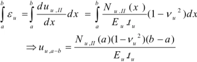
, . ( ) 2
(1 )
.
b b b
u II u II
u u
u u
a a a
d u N x
d x d x
d x E t
2 ,
,
( )(1 )( )
.
u II u
u a b
u u
N a b a
u E t
(18)Similar to Equation 18, Equation 19 is derived for the lower adherend.
d, d.
( )
(1
2)
.
b b b
II II
d d
d d
a a a
du
N
x
dx
dx
dx
E t
2 u,
,
[
( )](1
)(
)
.
II d
d a b
d d
P N
a
b a
u
E t
(19)The last boundary condition is obtained by replacing Equation 19 and Equation 18 with Equa-tion 17 and then EquaEqua-tion 16. So equaEqua-tion 20 can be written as follows:
2 2
,
( )(1
)(
)
(
,( ))(1
)(
)
.
.
u II u u II d
a I III
a u u d d
N
a
b a
P N
a
b a
G
t
E t
E t
(20)By using boundary conditions (Equation 10 to 16), stress distribution in adherends is deter-mined. Shear stress distribution along the adhesive can be found by Equation 21-a for Section I and Equation 21-b for Section II.
)
sinh(
)
cosh(
)
(
x
A
1k
kx
B
1k
kx
I
(21-a))
sinh(
)
cosh(
)
(
x
A
3k
kx
B
3k
kx
III
(21-b)3 FINITE ELEMENT SOLUTION
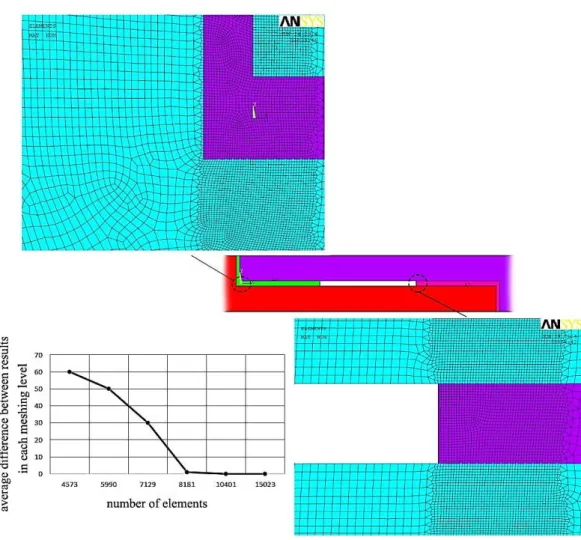
The finite element method was employed as the second method to verify analytical solution. A two-dimensional model was created by ANSYS. Element PLANE 182 was chosen to mesh the geometry model. This four-node element has two degrees of freedom at each node.( translation in the nodal x and y directions). Plane strain option of the element was selected. External tensile load(500kN/m) was applied to the right edge of the upper adherend and the left edge of lower adherend was con-strained both in x and y directions. The geometry and material properties of joint is reported by table 1 and 2. Figure 2 shows the meshed FEM model and its convergence diagram.
ta 0.32 mu 0.2
tu 1.6 md 0.2
td 1.6 l 16
hu 1.92 a 5
hd 1.92 b 11
Latin American Journal of Solids and Structures 13 (2016) 331-343
Eu 71 GPa
νu 0.3
Ed 71 GPa
νd 0.3
Ea 5.64 GPa
νa 0.33
Table 2: material properties of adhesive and adherends.
Figure 2: 2-D Finite element model and convergence diagram.
4 RESULT AND DISCUSSION
4.1 Central Void
distri-Latin American Journal of Solids and Structures 13 (2016) 331-343
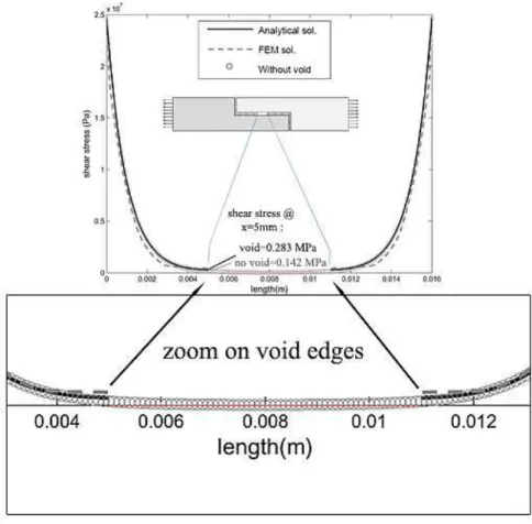
bution can be compared in the figure. Also shear stress distribution of the normal joint (without void) is plotted. Note that shear stress results in adhesive layer were obtained at mid-bondline in ANSYS model.
Figure 3: shear stress distribution in adhesive with central void (a5, 11b ).
Figure 3 indicates that this void has no effect on peak shear stress. But on the edges of the void, stress increases about 49%. Also FEM solution verifies the analytical results except near the void edges. FEM predicts 5.5% higher stress than analytical solution.
4.2 Acentric Void
Shear stress distribution in adhesive layer which suffers a void with relative length of 0.125 located near the left edge of joint (
a
3mm, 5mm
b
) is shown by Figure 4. The peak shear stress in this case occurs at the left edge of overlap length. It has been increased just 0.1% than a normal joint.Analysis of void edges reveals that stress increases 51% for the left side and becomes 3.8 times higher for the other side. The effect of void (a2mm, 4mmb ) on longitudinal stress in the upper
Latin American Journal of Solids and Structures 13 (2016) 331-343 Figure 4: shear stress distribution in adhesive with void (a3, 5b ).
Latin American Journal of Solids and Structures 13 (2016) 331-343
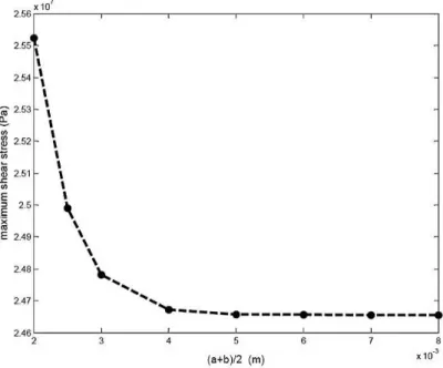
It is observed that stress increases for a region of the adherend beside the left half of void, but it decreases beside the right half of void. Figure 6 depicts the effect of central void length on peak shear stress in adhesive layer.
Figure 6: effect of a central void length on peak shear stress.
Figure 6 shows that for the voids shorter than 0.6 (relative length), no change is observed, but that for longer voids, peak stress increases rapidly. To study the influence of void location on peak shear stress in the adhesive layer, the peak shear stress for several voids with the same length (3mm) but a different location is plotted in Figure 7. The void gradually approaches the left edge of the joint. The void location is assumed to be in its center.(
2
a b
). For the voids between the cen-ter and one-fourth of the overlap length, no change in peak is observed. However, as the cencen-ter of the void approaches the end of the overlap length (in the first one-fourth), peak shear stress in-creases rapidly.
To compare the effect of void on single-lap and stepped-lap joints, a single-lap joint without load eccentricity suffering from a void (a3mm, 5mmb ), Rossettos and Jang (1993), and its
Latin American Journal of Solids and Structures 13 (2016) 331-343 Figure 7: effect of void location on peak shear stress.
Latin American Journal of Solids and Structures 13 (2016) 331-343 5 CONCLUSION
A void in the adhesive layer separated the layer into two sections. By using an equilibrium equa-tion, differential equations of three zones for adherends and two sections of adhesive were derived. The set of equations was solved by applying boundary conditions at both void edges and two ends of overlap length. Shear stress distribution of the adhesive layer was obtained for several voids with different locations or sizes. The FEM solution was compared with the analytical solution and satis-factory agreement was observed. Results indicated that a void does not change peak shear stress in the adhesive layer until one of its edges approaches one of two ends of overlap. However, on both edges of the void, shear stress increases even for central or short voids. Totally, as the critical re-gions of joint are two ends of the overlap length, a far void from these rere-gions can be neglected. Critical limit can be expressed as 20% of the overlap ends. It was found that rise in peak shear stress for a single-lap joint is 19%, but it is reported at about 2% for the stepped-lap joint. Avoid in the single-lap joint causes a 60% increase in shear stress on the left edge, but it is only 40% for the stepped-lap joint. On the right side of the void, shear stress becomes four times higher in both joints. Thus, the stepped-lap joint has a better performance in reducing the effects of the void on shear stress field when compared to the single-lap joint. this fact can be related to the butted re-gions.
References
Volkersen, O., (1938). Die Niektraftverteilung in Zugbeanspruchten mit Konstanten Laschenquerschritten. Luftfahrtforschung 15: 41–68.
Goland, M., Reissner, E., (1944). The stresses in cemented joints, Journal of Applied Mechanics, Trans. ASME: 66: 17-27
NASA-CR-112236 NASA Langley contract report. Hart-Smith, L.J., (1973). Adhesive-bonded single-lap joints. Chun, H., (1999). Stress analysis of adhesively-bonded single-lap joints, Journal of Composite Structure 47: 673-678 NASA-CR-112235 NASA Langley contract report. Hart-Smith, L.J., (1973). Adhesive-bonded double-lap joints. da Silva, L., das Neves, P., Adams, R.D., Spelt, J., (2009). Analytical models of adhesively bonded joints-Part I: Literature survey, International Journal of Adhesion & Adhesives: 41-47.
NASA-CR-112237 NASA Langley contract report. Hart-Smith, L.J., (1973). Adhesive-bonded scarf and stepped-lap joints.
Mortensen, F., Thomsen, O.T., (1997). Simplified linear and non-linear analysis of stepped and scarf adhesive-bonded-lap-joints between composite laminates, Journal of Composite Structures 38: 281-294
Gleich, D.M., (2002). Stress analysis of structural bonded joints, Delft University Press (Delft).
Ichikawa, K., Shin, Y., and Sawa, T., (2008). A Three-dimensional Finite-element Stress Analysis and Strength Evaluation of Stepped-lap Adhesive Joints Subjected to Static Tensile Loadings, International Journal of Adhesion and Adhesives 28: 464–470.
Sawa, T., Ichikawa, K., Shin, Y., (2010). A Three-dimensional Finite-element Stress Analysis and Strength Evalua-tion of Stepped-lap Adhesive Joints Subjected to Bending Moments. InternaEvalua-tional Journal of Adhesion and Adhe-sives 30: 298–305.
Kimiaeifar, A., Lund, E., Thomsen, O.T., Sorensen, J.D., (2013). Asymptotic Sampling for reliability analysis of adhesive bonded stepped-lap composite joints, J. of Eng. Structures 49: 655-663
Latin American Journal of Solids and Structures 13 (2016) 331-343
Rossettos, J.N., Zang, E., (1993). On the peak shear stresses in adhesive joints with voids, J. Appl. Mech 60: 559– 560.
Lang, T.P., Mallick, P.K., (1999). The effect of gaping on the stresses in adhesively bonded single-lap joints. Int. J. Adhes. Adhes. 19: 257–271.
Chadegani, A., Batra, R.C., (2011). Analysis of adhesive-bonded single-lap joint with an interfacial crack and a void. Int. J. Adhes. 31: 455–465.
Bavi N. (2011). Stress distribution in adhesively bonded joints including matrix extension, MSc thesis (in Persian), Shahid Chamran University, Iran
Shishesaz, M., Bavi, N., (2012). Shear stress distribution in adhesive layers of a double-lap joint with void or bond separation, J. of Adhesion science and technology: 1-29
Ghoddous, B., Shishesaz, M., (2014). Shear stress analysis of adhesively-bonded stepped-lap joint using analytical method and numerical model, the 22nd annual Intl. conference on mech. Eng. ISME-2014, Ahvaz, Iran
Karachalios, E.F, Adams, R.D., da Silva, L.F.M, (2013). Strength of single lap joints with artificial defects, J. of adhesion and adhesive 45: 69-76