Abstract—Distribution transformer is one of the most important power equipments in distribution network, whose running state exercises a great influence on the stability of the network. Transformer Terminal Unit (TTU) is an effective device to monitor the running state of transformers in the distribution automation system. In this paper, we study a new smart TTU which uses ARM7 series chip as processor, equipped with ATT7022B based electric meter module and GPRS module for remote data transmission control. We focus on the corresponding hardware, software design and the measurement principle of harmonics of TTU. The new TTU can measure the electric parameters of the distribution transformer precisely. Taking advantage of the powerful ARM processor, it can analyze harmonic of the power line effectively. Due to the always-on-line feature of GPRS, TTU can achieve reliable communication with the remote terminal and the master station. Compared with other similar units, the new unit outperforms in terms of real-time, precision and reliability, which can fully meet with the high-speed development of distribution automation system.
Keywords—ARM, GPRS, ATT7022B, Transformer Terminal Unit (TTU).
Original Research Paper DOI: 10.7251/ELS1317144W
I. INTRODUCTION
ISTRIBUTION transformers are widely used in distribution networks. But at present, most of distribution transformers are not equipped with intelligent monitoring
Manuscript received 13 May 2013. Received in revised form 17 October and 18 November 2013. Accepted for publication 16 December 2013.
The paper is supported by the following projects: Natural Science Foundation of China (61071087); National Natural Science Foundation of Shandong province (ZR2011FM018); National Natural Science Foundation of Shandong province (ZR2012EEM021); Innovation projects of Shandong postdoctoral (201103099).
Na Wu is the Doctoral Candidate and Lecturer of College of Information and Electrical Engineering, Shandong University of Science and Technology, Qingdao, Shandong China. (Tel: 86-532-86057525; fax: 86-532-86057155; e-mail: [email protected]).
Yinjing Guo is the Professor of College of Information and Electrical Engineering, Shandong University of Science and Technology, Qingdao, Shandong China. (e-mail: [email protected]).
Yongqin Wei is the Lecturer of College of Information and Electrical Engineering, Shandong University of Science and Technology (e-mail: [email protected]).
Aying Wei is the Doctoral Candidate and Lecturer of College of Information and Electrical Engineering, Shandong University of Science and Technology (e-mail: [email protected]).
devices with the ability of communication. In recent years, some efforts have been made to distribution transformers in terms of non-oiling, combination and maintenance-free at home, therefore some automation equipments for transformers in the distribution system have come forth. Unfortunately due to the limited economic strength of China, it is impossible to set uniform provision for distribution transformers and most of the existing automation equipments are high-cost that are unsuitable to be used universally for enormous distribution transformers. With the in-depth development of distribution automation, Transformer Terminal Unit (TTU) has a very broad market demand [1].
TTU is an important component of distribution automation system. It is the remote terminal which is installed in the bottom of the system and used for monitoring the real-time operation parameters of the distribution transformers [2]. Under the market demand of distribution transformers, it is therefore desirable to design a monitoring device which can collect the data precisely, meanwhile it can communicate with the remote terminals and monitoring center reliably [3].
The remainder of this paper is organized as follows: Section 2 summarizes the research situation of TTU in China and abroad. In section 3, we propose the structure of transformer monitoring system and introduce the function of TTU in the system. The overall design of TTU is consequently given in section 4. Section 5 discusses the detailed hardware design of each part of TTU. Section 6 is the software design of TTU, and we focus on the algorithm of harmonic analysis and the flow chart design of the main program. Section 7 presents the analysis of harmonic detection results. Section 8 is the conclusion of the paper.
II. THE DEVELOPMENT AND RESEARCH OF TTU
In traditional design of TTU, single chip microcomputers such as 8031 or 8051 are mostly used as the CPU. This kind of single chip has many disadvantages such as slow data processing rate, small memory capacity, relatively simple interface circuit and more complicated hardware design of data acquisition. Most of the analog acquisition modules in traditional TTU design are as follows. Voltage and current signal firstly flowed into the corresponding sensors, then the filter circuit, sample hold circuit, multiplex switch, A/D conversion, and finally entered into the CPU. The communication module mostly adopts RS-485 Bus or other wired communication mode. All of them need laying so much
Study on New Smart Transformer Terminal Unit
Based on ARM and GPRS Network
Na Wu, Yinjing Guo, Yongqin Wei, Aying Wei
D
communication line resulting in increasing the investment of hardware inevitably. Moreover most designing of TTU did not consider harmonic analysis function of the distribution line. Thus many scholars have made some improvement in the designing of TTU in recent years, where outstanding contributions are summed up as follows: New single chip microcomputers such as MSP340, SCM F449 and F2012 are adopted as CPU [4]. Double CPU structure is used in reference [5]. Powerful ARM is used as the microprocessor in [1] [6] [7], but the data acquisition circuit and communication circuit of them are designed in the traditional way. In [2] [3] [9], the design of communication circuit is only the way of GPRS wireless communication, and no improvement has been made in other ways. In [8], only data acquisition circuit has been made for certain improvement, and the electric energy meter chip is adopted. The contribution of [9] is the harmonic analysis circuit in the design of TTU. Through analysis of all literatures above, it's obvious that not all aspects are considered comprehensively in the design of TTU.
For these reasons shown above, this paper designed a new intelligent transformer terminal unit (TTU) in distribution network. This device adopted ARM7 series chip as processor, which would improve the processing speed of the system greatly. GPRS wireless communication mode is chosen in communication module, which saves the investment in communication line enormously. Electric energy metering chip ATT7022B is used in the design of data processing module, which simplifies the hardware design of the data acquisition circuit and the harmonic analysis function is considered in the design too. This device combined many functions in one, realized the real-time data acquisition and control, alarm in time and solved the problem of remote data transmission between distribution transformers and master station effectively.
III. THE STRUCTURE AND FUNCTION DIVISION OF
DISTRIBUTION TRANSFORMER MONITORING SYSTEM
The distribution transformer monitoring system is composed of Transformer Terminal Unit (TTU), GPRS wireless communication network and master station. TTU is installed in the transformer, which mainly accomplishes data collection, analysis and record, pops up alarm information in time when the transformer has abnormal events, receives the command from the master station and implements it. GPRS wireless communication network is the bridge of data transmission between the master station and transformers. Master station receives the real-time data of transformers through GPRS wireless communication network, implements further data processing and saving, consequently issues control command. Therefore the system can achieve a comprehensive monitoring and control for distribution transformers. At the same time, it can provide users with a visual interface and let dispatches obtain monitoring performance of far transformers in time for never leaving home. The structure of transformer monitoring system is shown in Figure 1.
Monitoring main station
Fig. 1. The structure of transformer monitoring system.
IV. OVERALL DESIGN OF TTU
A. The Main Function of TTU [10]
(1) Measurement capabilities: TTU can online measure three-phase voltage, current, harmonic current, active power, reactive power, electric energy, power factor, etc.
(2) Recording capabilities: TTU can online record all measured values of the parameters mentioned above which includes minimum value and maximum value.
(3) Statistical capabilities: TTU can online make a statistical investigation of blackout time in one year, voltage qualified rate, switching times of capacitor, etc.
(4) Analysis Functions: TTU can complete online and offline analysis of current curves, voltage quality, harmonic distortion rate, etc. and give corresponding governance methods.
(5) Protection Functions: TTU can provide an alarm signal in real time. It has perfect communication function and operation record function, and can record all the operation events for analysis.
(6) TTU can control the switching of capacitors accurately, keep the three-phase low-voltage balance of transformer and adjust the power factor to the optimal state.
B. The General Structure Design of TTU
According to the monitoring system structure introduced above and the main function of TTU, the hardware architecture of TTU is shown in Figure 2.
Ia,Ib,Ic Ua,Ub,Uc
switch input
switch output
Fig. 2. The hardware architecture of TTU.
In the hardware architecture of TTU, chip LPC2138 based on ARM7TDMI-S is the core of the system. It consists of such modules as analog input module, electric energy measurement
circuit, switch input circuit, switch output control circuit, the keyboard and LCD display circuit, GPRS wireless communication circuit, voice alarm circuit, clock circuit, watchdog circuit, uninterruptible power supply (UPS), etc.
V. HARDWARE DESIGN OF TTU
A. Design of Analog Input Module
Analog input module is responsible for voltage and current collection from three-phase transformer. It has two parts of the signal conditioning circuit and chip ATT7022B for electric energy metering.
1 Current and Voltage Signal Conditioning Circuit
In the three-phase current signal collections, phase current IA is changed into suitable voltage signal for measuring range of chip ATT7022B by 10A/10mA current transformer and resistance. 1.2kΩ resistance and 0.01uF capacitance constitute the anti-aliasing filter and the voltage signal after filtering flows into the current input channel of ATT7022B. The principle of three phase voltage signal collections is the same as three phase current collection circuits. Because the voltage transformer adopts 2mA/2mA current-mode voltage transformer, voltage UA needs to be changed into 2mA current signal by the resistor R1 firstly [11]. The current and voltage conditioning circuits are shown in Figure 3.
Fig. 3. Circuit diagrams of current and voltage conditioning.
2 ATT7022B Electric Energy Metering Chip
After the processing of signal conditioning circuits, three phase voltage and current enter into the electric energy metering chip ATT7022B. ATT7022B is a three-phase power special measurement chip which has high precision and anti-pilfering electricity function. The chip is used to measure parameters of voltage, current, active power, power factor and frequency, etc, and monitor the running status of three-phase power line. Because of the open phase threshold register of ATT7022B, bit0, bit1and bit2 in measurement register 0x2C would give a status flag of three-phase voltage-absent when the detected voltage effective value in the register is lower than that
of open phase threshold register. Thus it can reliably judge whether the power transmission line is lack of a phase or a power outage occurs. ATT7022B can also judge whether the voltage and current phase sequence are normal by detecting the sequence of zero-crossing point of voltage and current signal [12]. The schematic diagram of the interface circuit between ATT7022B and LPC2138 is shown in Figure 4.
Fig. 4. Schematic diagram of the interface circuit between ATT7022B and LPC2138.
B. Design of Switch Input Module
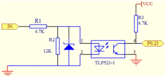
Switch input signal of TTU mainly includes remote signal and remote pulse signal. Remote signal indicates the position status of the circuit breaker of the distribution transformer and the action status of protection and automatic devices. Remote pulse signal is to read the pulse signal of multi-function electric meter. Switch input signal must be converted to 3.3V logic signal by the isolation of the optocoupler firstly and then enters into I/O port of LPC2138. The circuit of the switch input module is shown in Figure 5.
Fig. 5. Circuit diagram of switch input.
C. Design of the Central Processing Module
The central processing module and peripheral circuit can realize data collection and data processing of all kinds of analog quantities and switching values. At the same time it can control the module sending and receiving short message and dialing the alarm telephone number. Because of the distribution monitoring function, the historical data and statistical data must be saved timely, besides it needs a memory bank to save a large number of control parameters. So a piece of AT241024 EEPROM is extended in the system, which storage space can achieve 1M byte.
D. Design of GPRS Wireless Communication Module
GPRS wireless communication module in the system is composed of MC55 produced by Siemens Company, which is the minimum size of three-frequency module in the market. In addition to the original function of GSM module, MC55 supports packet service functions, which embeds TCP/IP protocol stack of high reliability and usability. So it is very suitable for wireless communication as a terminal module [13].
(b)Conditioning circuit of A-Phase current.
(a) Conditioning circuit of A-Phase voltage.
Such functions of MC55 as power on and off, working mode and working condition, etc. are controlled by LPC2138. Serial port 0 of MC55 and serial port 1 of LPC2138 are used to realize the TCP/IP network communication in the system. LPC2138 realizes commands and data control with MC55 through AT command.
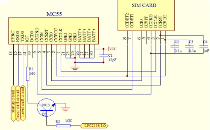
MC55 has 50 pins which can be divided into the function modules as following: power charging management module, double serial ports module, double audio interface module and SIM card interface module. The SIM card interface module provided by MC55 can drive SIM holder directly. The CCIN pin of MC55 is designed for testing SIM card. When the SIM card is inserted, the output level of CCIN is high and MC55 is on work, otherwise the output level of CCIN is low and MC55 is closed. CCIN pin controls the switch of MCU through the electrical level in order to prevent the damage of MC55 when SIM card is pulled out in the process of work. In order to guarantee the electromagnetic compatibility, the distance between SIM card and MC55 is no more than 200mm [13]. The interface circuit between MC55 and SIM card is shown in Figure 6.
Fig. 6. Diagram of interface circuit of MC55 and SIM card.
The typical voltage of MC55 is 2.65V when the serial-port sending and receiving data, while the voltage of ARM7 is 3.3V. So direct connection between them may cause data error, and two electric level conversion circuits are designed, which respectively convert 5V to 2.5V, 2.5V to 5V. Two bipolar junction transistors are used in each conversion. Electric level conversion circuits of MC55 are shown in Figure 7.
Q4
9013 Q5
9013 R4 10K R3 10K
R6 10K
VCC-2.5V
R5 10K
VCC
MC55TXD
MCU TXD
Q1 9013
Q2 9013 R10 10K
R11 10K
VCC-5V
R9 10K R8 10K
MC55 RXD
MCU RXD
Fig. 7. Diagram of electric level conversion circuits.
E. Design of Other Major Modules
1 Design of the keyboard and LCD module
In the distribution automation system, we can realize the function of data acquisition through remote communication. But on many occasions, users need to understand real-time situation of the transformer directly. Thus, the Liquid Crystal Display function is extended, which provides a great convenience for users. So it is very helpful to field maintenance and detection for distribution transformer [9]. The Liquid Crystal Display module MS12864R is used to display Chinese and graph. We can control the content of Liquid Crystal Display and modify the field parameters of TTU by the key module. Six keys are designed in the key module. Input signal of the key is detected by the interrupt pin GPIO of ARM, and the interrupt signal of the key is provided by the chip 74LS14.
2 Design of the Alarm Module
Once the transformer has been stolen, broken line fault or power failure occurs, alarm module will immediately detect out them and report to operators on duty through GPRS short message or voice alarm and store the alarm data into the database in the end. In the electronic map of master station, the corresponding emergency alarm will keep flashing, which will display the time, location and type of the alarming. So it is very convenient for the staff of the scene to arrive at the alarm point in time.
The design of the power module and clock module circuit is no longer described.
VI. SOFTWARE DESIGN OF TTU
A. Algorithm Selection
Due to the electric energy metering chip completing the collection of three-phase voltage and current, and calculating parameters such as voltage, current, power, electric energy and so on, the software design of the measurement module is relatively simple. Here only the algorithm of harmonic analysis is introduced [14].
In power system, the equation of voltage and current is as follows.
k 1
u ( )t Uk sink
ω
t∞
=
=
∑
(1)
k 1
( ) ksin( k)
i t U kωt θ ∞
=
=
∑
−(2)
As periodic function, voltage and current signal can be
decomposed into the Fourier series as follows.
0 1
x n n (3.a)
n
( t ) A ( A cos n tω B sin n t )ω
∞
=
= +
∑
+or
0 1
x n n (3.b)
n
( t ) A C sin n tω ψ )
∞
=
= +
∑
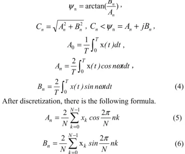
+In the formula,ω =2πf is the corresponding angular frequency, n=1, 2… is the harmonic order. A0is the DC component which is the average value of one cycle in the periodic function.
A
n and Bn are the coefficient of Fourierseries, which are the rectangular coordinate component of N harmonics. The corresponding n harmonic vector is as follows.
) arctan( n
n n
A B
=
ψ ,
2 2
n n n A B
C = + ,Cn<
ψ
n= An+ jBn,0 0
1 x T
A ( t )dt T
=
∫
,0
2 x T n
A ( t )cos n tdt
T ω
=
∫
,0 2 T n
B x( t ) sin n tdt
T ω
=
∫
(4)After discretization, there is the following formula.
1
0
2 N 2
n k
k
A x cos nk
N N
π −
=
=
∑
(5)
1
0
2 2
x N
n k
k
B sin nk
N N
π −
=
=
∑
(6)
In the formula above, n = 0, 1, 2, … , N – 1 is the harmonic order, k = 0, 1, 2,…, N – 1 is the sampling number, and xkis the sampling value at k time.
But in the actual measurement, the functional relationship between the formula (1) and (2) is unknown, we can get the limited length sequence, whose cycle is N, through the voltage and current sampling circuits. According to the theory of digital signal processing, the Discrete Fourier Transform (DFT) is expressed as follows.
1 2
0
0 k 1
n
N j k
N
k
X ( n ) x( k )e π ( n )
− −
=
=
∑
≤ ≤ − (7)In the equation, X(n is the size of the n times harmonic component.
From the equation (4), (6), (7), we can get the following equation.
2
n n
X ( n ) A jB
N = − (8)
So the amplitude of each harmonic, the phase angle between the same harmonic, etc. can be got by Discrete Fourier Transform (DFT) in actual measuring system. But DFT needs extensive calculation, so Fast Fourier Transformation (FFT) is used in the system.
B. Flow Chart of Software Design
The working process of the main program of TTU is as follows. The system is powered on and initialized firstly, that is setting the value of each control register of the ARM which includes system clock, I/O port, UART, SPI, I2C, SSP, interrupt timer, etc. Then it carries out a self-checking on the special chips including memory, real-time clock, LCD module, electric energy metering chip ATT7022B, etc. If there is some
abnormal chip, the system would alarm, otherwise continue to run the main program.
The main program flow chart is shown in Figure 8. It judges whether the circuit breaker of the transformer circuit has acted or not firstly. If the circuit breaker has acted, the system would alarm, or go into the acquisition of voltage, current and other parameters, and perform harmonic analysis. According to the acquisition parameters, we can diagnose whether the transformer working properly. If there is a fault of transformer, the system would alarm, or go into the next round of data collection.
Fig. 8. The flow chart of the main program.
Subroutine contains such modules as data acquisition module subroutine, display subroutine, fault alarm subroutine, harmonic detection subroutine, GPRS communication module subroutine, etc.
VII. ANALYSIS OF EXPERIMENTAL RESULTS OF HARMONIC
DETECTION
Harmonic source generator is adopted in order to output harmonic signal.If each harmonic of the harmonic source are set in table I, each harmonic phase can be given freely. After harmonic signal sampled (each cycle by 128 points) and calculated by FFT, each harmonic content rate can be got, which will be compared with the set value. Measurement value of harmonic percentage is shown in table II.
TABLEI
HARMONIC PERCENTAGE OF SETTING
Harmonic frequency of setting
3 5 7 9 11 13 15 Harmonic ratio of
setting %
2.5 4.0 3.5 1.8 1.0 0.9 0.7
TABLEII
HARMONIC PERCENTAGE OF MEASUREMENT
Harmonic frequency of measurement
3 5 7 9 11 13 15
Harmonic ratio of measurement
%
2.491 3.982 3.488 1.789 0.990 0.902 0.697
VIII. CONCLUSION
Facing the demand of users, in this paper we design an easy-to-use distribution transformer monitoring terminal with powerful functions by use of advanced techniques. Compared with similar products, the proposed system has completed not only all basic functions of TTU but also the harmonic detection which reduced the harmonic harm to distribution transformer and utility grid. We achieve the data acquisition and processing and some other management functions of distribution transformer by GPRS wireless communication mode, which has the outstanding advantages in terms of cost-effective, fully functional, easy maintenance management, etc. This new system has been put into running for more than a year in distribution department of Jining Power Supply Company in China. Operation practice shows that the system has achieved satisfactory results in the control accuracy, reliability, real-time and harmonic analysis so that it has a satisfied promotion and application value.
With the development of microelectronics technology and communication technology, the TTU designed in this paper can also be further improved and the below development directions
can be taken. Double CPU structure such as ARM+DSP can be used and other parts of the hardware design can adopt new chips in the market, etc. The functions of TTU can also be further enhanced to collect the information of distribution transformer as much as possible and it can better promote the development of intelligent distribution network.
REFERENCES
[1] Ma Ming, Design of Distribution Transformer Monitoring Terminal Unit (TTU) Based on ARM, Master . Thesis, Dept. North China Electric Power University, China, 2010.
[2] Li Guanghui, Chen Zhiying, Design of Distribution Remote Terminal Unit (TTU) Based on DSP , Advanced Technology of Electrical Engineering and Energy, Vol.23, n.3, July 2004,pp.72-75.
[3] Li Shuiping, He Jianjun, Research on On-line GPRS-based Monitoring System of TTU , Automation Instrument. Vol.29, n.9, Sep. 2008,
pp.33-39.
[4] Tao Weiqing, Li Lin, YANG Mei, The distributed transformer terminal unit with function of reactive power compensation control based on MSP340 , Power System Technology, vol.30, supplement , oct.2006,
pp.414-418.
[5] Tao Weiqing, WANG Fujun, Development of intelligent transformer terminal unit based on dual MCUs , Journal of Hefei University of Technology, Vol. 31, n. 8, Aug. 2008,pp.1172-1175.
[6] Xie Zhiyuan, Ma Ming, Guo Yihe, Design of transformer terminal unit based on ARM . Telecommunications for Electric Power System, Vol.31, n.210, Apr. 2010,pp.28-31.
[7] Xie Zhiyuan, Ma Ming, Design of TTU communication module based on PLC , Measurement Control Technology and Instruments May.2010,pp.94-99.
[8] He Wei, Cai Meiyuan, Liu Xiliang, Design of transformer remote monitoring system based on GSM , Power System Protection and Control, Vol.37, n.1, Jan. 2009,pp.83-103.
[9] Shi Juanjuan, The design and implementation of distribution transformer terminal based on uClinux , Master. Thesis, Dept. Wuhan University of Technology, China, 2008.
[10] Li Ruxiong, Lin Meijin, The Study of Trans former Terminal Unit(TTU) Based on GPRS Network , Microcomputer Information, Vol.22, n.32, 2006,pp.146-148.
[11] Zhang xiaoming, Gong Maofa, The Design of Transformer Comprehensive Monitoring Alarm System Based on the C8051F360 + TC35i + ATT7022 , Electric Power Automation Equipment , Vol.31, n.9 , Sept.2011,pp.139-143.
[12] User's Manual of ATT7022, Design of Power Integrated Circuit, Limited Company of Zhuhai , EBOL.2005.2010-05-05. http:// www.actions semi.com/ Actions V8 /Chinese/ Product View. aspx?cat= 25.
[13] Siemens, MC55/ M C56 Hardware Interface & MC55 AT Command and Set [R], Siemens, 2006.
[14] Zhao Wen-lei Li Hui, Study of Measuring Algorithms for Electric Parameters with Harmonic , Journal of Dalian Railway Institute, Vol.24, n.4, 2004,pp.58 -62.