wind turbine in the manmade wind
field from air conditioner of buildings
K.H. Goh, Fei Duan*ABSTRACT
Harnessing waste energy from the manmade air fields of buildings presents a new area of renewable energy to explore. Due to the unpredictability of the natural wind, this study is to evaluate the practicality for harnessing waste energy from the air conditioner exhaust units which are a more constant and predictable source available in the buildings. A prototype of the micro wind turbine has been designed to minimize the negative effect of the exhaust sources. After the micro wind turbine was manufactured, the performance of the turbine was tested in the selected air conditioner exhaust unit. Increasing the rotor solidity and decreasing the resistance of the generator contribute to improved starting torque and decreased generator break in torque respectively in the design. The power generation of the micro wind turbine increases with an increase of the rotor speed. The 24-hour operation of the prototype presents an observation for both exhaust performance and power generation prediction when the prototype is mounted on the exhaust unit.
Keywords:micro wind turbine, manmade wind field, waste energy
Cite this article as: Goh KH, Duan F. Performance of a prototype micro wind turbine in the manmade wind field from air conditioner of buildings,QScience Connect2013:4
http://dx.doi.org/10.5339/connect.2013.4
http://dx.doi.org/ 10.5339/connect.2013.4
Submitted: 27 December 2012 Accepted: 21 January 2013
ª2013 Goh, Duan, licensee Bloomsbury Qatar Foundation Journals. This is an open access article distributed under the terms of the Creative Commons Attribution license CC BY 3.0 which permits unrestricted use, distribution and reproduction in any medium, provided the original work is properly cited.
1. INTRODUCTION
Rapid globalization and urbanization of the world has resulted in a significant increase in demand for energy, which is mainly depended on fossil fuels. The dramatic growth of the fuel consumption might inevitably lead to a disaster of lack of the fossil fuels.1The problem promotes the application of developing the cleaner sources of energy. Among them, the wind turbine technology has been rapidly improved.2Manwell et al.3suggested that the wind energy application can be improved on materials science, computer science, aerodynamics, testing, and power electronics. The various fields have been developed on materials optimization for blade construction and accurate designs on the wind turbine performance to generate electricity.4 – 6The capacity of the power generation is found to depend on the environmental factors including geographical location, wind speed, wind availability, etc. However, the wind turbine power generation using the natural wind is normally highly unstable because the natural wind is unpredictable, especially for building-mounted wind turbines in the cities. The studies have been conducted to evaluate the performance of the kind of the building wind turbine, and pointed out the limitations of the most commercially available building wind turbine.5,6On the other hand, the exhaust of various urban buildings are more predictable, and the exhaust units of the building produce significantly waste energy to the surroundings. Harnessing the waste energy from these manned wind fields provides a more reliable energy source.7,8The area remains under-explored. Installing of a micro wind turbine on such an exhaust unit as an air conditioner unit requires us to resize the wind turbine into a small scale. A major problem in a mini wind turbines is the small torque due to the small rotor diameter, resulting in difficulty to start rotating in low speeds.9,10In the conditions, one of the methods to increase the starting torque would be to increase the rotor solidity of the wind turbines. The solidity is defined with the blade area divided by the rotor area. Duquette and Visser11indicated that increasing rotor solidity at 15– 25 % increased the power coefficients while decreased the tip speed ratio at 2 – 4, in which the ratio is between the rotational speed of the tip of a blade and the actual velocity of the wind. The lack of torque also suggests that the total mechanical resistance of the mini turbine due to the friction has to be kept to a minimal. According to the work of Gipe,12the micro wind turbines are defined with a rotor diameter less than 1.25 m. A 0.5 m prototype (mF500) was designed and tested by Hirahara, et al.8 However, if the wind turbine totally covers the exhaust unit, the back pressure could reduce the performance of exhaust. A 0.5 m rotor would still be too large for installation on typical exhaust units for buildings. This paper is to develop a micro wind turbine that can be mounted on the existing air conditioner exhaust units, but minimize the negative effect of air conditioners. The performance on power generation has been studied by testing the micro wind turbine.
2. MICRO WIND TURBINE DESIGN AND PROTOTYPE
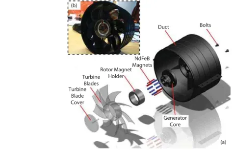
A micro wind turbine was designed, as shown inFigure 1(a). The micro wind turbine is made of turbine blades, turbine blade cover, Neodymium Iron Boron (NdFeB) magnets with a holder, a duct for wind
(a)
Duct Bolts
NdFeB Magnets Rotor Magnet
Holder Turbine
Blades Turbine
Blade Cover
Generator Core (b)
flow, and necessary bolts. The selection of Neodymium Iron Boron (NdFeB) magnets has not been optimized in the present study. The manufactured prototype is illustrated inFigure 1(b)based on the design. The specifications of the prototype can be found inTable 1. The power generator is the brushless one to decrease the mechanical resistance,13,14which is modified from a personal computer (PC) fan motor. The rotor magnet material is NdFeB. The prototype uses 9-blade fan with a diameter of 110 mm coupled with a brushless DC (Direct Current) generator. The 9-bladed fan was selected due to increasing in rotor solidity and being easy to start up the turbine. The power output is AC (Alternating Current) and then is rectified through a Schottky bridge rectifier into DC immediately for a convenient analysis. All the components are in a duct as shown inFigure 1(b). The inclusion of the duct provides several advantages, namely, turbine protection during operation, reduction of crosswind effects, channeling of the turbulent exhaust velocity, mounting properly, and allowing its attachment to concentrators, diffusers and other attachments. A stator inside the duct is added for mounting the generator securely to the duct. This ensures that the losses through vibrations are minimized. The relative costly part is the 9-blade fan, however, the total spending of the fabricated wind turbine prototype is less than a hundred dollars without considering the manpower.
3. EXPERIMENTAL TEST
3.1 Electric power output of the micro wind turbine
Electric power output was evaluated before the micro wind turbine was tested in an air conditioning exhaust unit. The micro wind turbine was mounted on a mechanical rotor to maintain the revolution per minute (RPM) of turbine at a constant value within^1% uncertainty, as illustrated inFigure 2. The DC signals were record by a PC via a Keithley 2612A system source meter while the AC signal was Table 1. The specifications of the micro wind turbine prototype.
Prototype components Specifications
Generator type Brushless (PC fan, 2 phase, 4 poles)
Rotor magnets NdFeB magnet
Electric output Rectified DC
Gearing –
Turbine blades 9 blades (110 mm in diameter)
Duct Ducted
Mechanical rotor Prototype
Sourcemeter DAQ
AC PC
DC
transferred to the PC via an Agilent 34970A data acquisition/switch (DAQ) unit. Thus, the power curve would be able to be determined from the measured voltage and current. RPM of the fan was calculated from the frequency recorded from the DAQ unit. RPM was converted by using the relation of 60£f/Np, wherefis the frequency with a unit of cycles per second, andNpis the number of pole pairs.
3.2 Air flow determination of the air conditioner exhaust
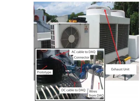
The exhaust unit used in the experiments is shown inFigure 3. The velocity of the wind flow exiting the air conditioner exhaust unit was measured with a flow meter (TSI VelociCheck) at the given positions as a function of height, distance from center line, and angular positions. To determine the effect of the air exhaust of the air conditioner, the micro wind turbine over a range of time can enable us to get a good representation of the exhaust cut-in and cut-out periods and also the performance of the prototype. The experimental setup is shown in the inset ofFigure 3. The prototype was mounted at the location for the highest exhaust wind velocity of the exhaust source. The voltage output was recorded by the computer through the cable. The test was lasted 24 hours to test the stability of the micro wind turbine designed while RPM of the fan was monitored from the DAQ readings.
4. RESULTS AND DISCUSSION
4.1 Micro wind turbine power output evaluation
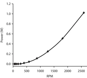
The relation of power output and RPM was investigated before the micro wind turbine was applied for the real test on an air condition exhaust unit.Figure 4shows the power as a function of RPM. The source voltage was multiplied with the current measured from the meters to give the power value. As seen there, the power generated increases parabolically as RPM of the rotor increases. It is seen that as the rotor speed (to simulate blade speed of wind turbine) increases, the generator torque is higher; as a result the power is generated at the modified generator with a higher power. The power output is about 0.1 W as the rotor speed is at 900 RPM, however it can reach over 1 W as the rotor is about 2600 RPM. The designed micro wind turbine shows the potential application in the high speed exhaust source. The error bars inFigure 4are the standard deviation of the experimental data. Under the mechanical rotor reached a steady-state conditions, the current and voltage readings were rather steady. RPM, voltage and current were recoded for 30 s with a rate of one time per second. The error bars of RPM are at about^20, as covered by the symbols inFigure 4. The instantaneous power is the product of the instantaneous current and instantaneous voltage, in which the voltage and current are
Exhaust Unit
DC cable to DAQ Prototype
AC cable to DAQ
Connector
Wires from DAQ
measured as a function of time. The standard deviation is at roughly^0.03 W. Simply speaking, the power output is proportional to the wind velocity, the practical testing was conducted in an air conditioner exhaust unit selected.
4.2 Exhaust flow velocity
The vertical velocities collected under the stable cut-in period of the air conditioner exhaust unit (Figure 3) are shown inFigure 5. The velocities are more uniform at the extent length (L) at 0.25 m than those at 0.10 m from the center line of the exhaust unit. It is shown that the highest exhaust velocity occurs at 330 degrees at a height (H) of 0.3 m for a fixed extension length of 0.1 m. For an extension distance of 0.25 m from the center line shown inFigure 5, the highest exhaust velocity is observed at the height of 0.05 m and 330 degrees. It can also be observed that an extension distance of 0.25 m generally improves the exhaust velocity available. The increase in velocity of the air with respect to the
L
H (a)
(b) (c)
(m/s) (m/s)
H=0.05 m; L=0.10 m
Exhaust H=0.20 m; L=0.10 m
H=0.30 m; L=0.10 m
H=0.05 m; L=0.25 m H=0.20 m; L=0.25 m H=0.30 m; L=0.25 m
Figure 5.Velocity at different heights, distance from center, and angular positions, measured position with the radius, L and height H shown in (a). The vertical velocities are at L¼100 mm, H¼50 mm, 200 mm, 300 mm in
(b); and at L¼250 mm, H¼50 mm, 200 mm, 300 mm in (c). 0.0
0.2 0.4 0.6 0.8 1.0 1.2
0 500 1000 1500 2000 2500
Power (W)
RPM
extension distance can be explained by the fact that the velocity of the air is accelerated as it travels along the length of the blade. Crosswinds from the environment were also observed to result in the disturbance of the exhaust wind flow as the height increases. However, the crosswind can be reduced by the micro wind turbine duct in the test. The best location to position the turbine is about 0.25 m from the center of the exhaust unit, 330 degrees, and the height of 0.05 mm. The mean wind velocity is 10.6 m/s. Under the normal cut-in running period of the air conditioner, the velocity is relative constant.
4.3 24-hour prototype test
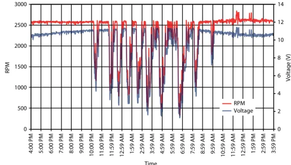
Figure 6shows the 24-hour performance of the micro wind turbine prototype when it was mounted on the air conditioner exhaust unit. Note that the diameter is about 0.7 m, while the diameter of the micro wind turbine is 0.11 m, the coverage of wind turbine is only 2.5%. Thus, the effect of the back pressure generated on the exhaust is very limited. The test was conducted in a clear day. The test period was from 4:00 pm to 4:00 pm in the second day. RPM from the exhaust unit was rather constant with a value 2597^41 in the period before 10:00 pm in the first day and after 10:00 am in the second day. The voltage is about 10.74 V with a standard deviation of 0.22 V. However, there is a cut-out period of 30 min every 1 hour of operation of the air conditioner from 10:00 pm to 10:00 in the second day. As the air conditioner stops, the speed of exhaust fan would reduce, but cannot stop immediately due to inertia, RPM of the micro wind turbine reduces as a result. Thus, the generated voltage reduces. The minimum value is about 1.25 V when RPM is at 325. When the air conditioner starts, RPM of the micro wind turbine is accelerated, driven by the increased exhaust mass flow until it reaches the constant RPM at about 2600. Consequently, the voltage increases to above 10 V. As shown inFigure 6, the patterns of RPM and voltage output matches in both cut-in and cut-out periods of the air conditioner. This present data can allow us to plan the usage of the micro wind turbine. If the turbine is switched to charge batteries during the day where the exhaust performance is constant and the charged batteries can then be used to supplement a system during the periods of low exhaust velocities to maintain a constant applications. Such a mini wind turbine is managed to light the light-emitting diodes (LEDs), which is being optimized. We have to note that the mounting of micro wind turbine has not changed the air conditioners working load and power consumption since it only covered relative small ratio of the exhaust area. In the test, the extra power consumption was not found if the micro wind turbine was mounted on the air conditioner exhaust unit. Thus, since the air conditioner exhaust gas is free, the period of capital cost return will depend on the potential application.
5. CONCLUSIONS
The micro wind turbine with a fan diameter at 0.11 mm has been designed and manufactured for collecting the waste energy in a manmade wind field of the air conditioner unit. The experiments were
0 2 4 6 8 10 12 14
0 500 1000 1500 2000 2500 3000
4:00 PM 5:00 PM 6:00 PM 7:00 PM 8:00 PM 9:00 PM 10:00 PM 11:00 PM 11:59 PM
12:59 AM 1:59 AM 2:59 AM 3:59 AM 4:59 AM 5:59 AM 6:59 AM 7:59 AM 8:59 AM 9:59 AM 10:59 AM 11:59 AM 12:59 PM 1:59 PM 2:59 PM 3:59 PM
Voltage (V)
RPM
Time
RPM Voltage
conducted to pre-test the design. The results show that the power output increases parabolically with an increase of RPM inFigure 4. The real test was conducted in air conditioner exhaust unit, which was observed to have various exhaust velocities at different positions inFigure 5. The region of the highest wind speed was used to mounted the micro turbine for 24-hour run. A 24-hour observation of the prototype’s RPM is the most stable from morning to evening when the exhaust fan is on. During the night, the exhaust roughly cuts out every half an hour for a period of half an hour, accordingly the micro wind turbine has the period voltage output shown inFigure 6. Since the wasted wind from the air conditioner has not given the equipment more power load, it is promising to harvest the wasted energy by using the micro wind turbine. The study of the exhaust performance, therefore, allows us to predict the performance of the designed micro wind turbines for collecting the waste energy from a manned wind field without affecting the performance of the exhaust sources. The technique is viable for low powered applications such as powering the LEDs for area lighting or battery charging. The further work is being conducted on exergy analysis of the manmade wind field and on fluid dynamic optimization of the wind turbine design. The results will be reported in the future.
Competing interests:The authors have declared that no competing interests exist.
Authors’ contributions:FD initiated the study; KHG conducted the design and experiments.
Acknowledgements
The authors want to thank the staff from Energy Systems Lab in School of Mechanical and Aerospace engineering at Nanyang Technological University.
REFERENCES
[1] Meadows DH.The limits to growth: a report for the Club of Rome’s project on the predicament of mankind. New York: Universe Books; 1972.
[2] Fleming PD, Probert SD. The evolution of wind-turbines – an historical review.Appl Energy. 1984;18:163– 177. [3] Manwell JF, McGowan JG, Rogers AL.Wind energy explained: theory, design and application. New York: Wiley; 2002. [4] Crawford RH. Life cycle energy and greenhouse emissions analysis of wind turbines and the effect of size on energy
yield.Renew Sust Energ Rev. 2009;13:2653– 2660.
[5] Bahaj AS, Myers L, James PAB. Urban energy generation: influence of micro-wind turbine output on electricity consumption in buildings.Energ Buildings. 2007;39:154– 165.
[6] Mithraratne N. Roof-top wind turbines for microgeneration in urban houses in New Zealand. Energ Buildings. 2009;41:1013 – 1018.
[7] Grant A, Johnstone C, Kelly N. Urban wind energy conversion: the potential of ducted turbines. Renew Energ. 2008;33:1157– 1163.
[8] Hirahara H, Hossain MZ, Kawahashi M, Nonomura Y. Testing basic performance of a very small wind turbine designed for multi-purposes.Renew Energ. 2005;30:1279–1297.
[9] Wang F, Bal L, Fletcher J, Whiteford J, Cullen D. Development of small domestic wind turbine with scoop and prediction of its annual power output.Renew Energ. 2008;33:1637 – 1651.
[10] Wright AK, Wood DH. The starting and low wind speed behaviour of a small horizontal axis wind turbine.J Wind Eng Ind Aerod. 2004;92:1265– 1279.
[11] Duquette MM, Visser KD. Numerical implications of solidity and blade number on rotor performance of horizontal-axis wind turbines.J Sol Energ – T ASME. 2003;125:425–432.
[12] Gipe P.Wind energy basics: a guide to home- and community-scale wind energy systems. 2nd ed. White River Junction, VT: Chelsea Green Pub. Co. 2009.
[13] Moradi H, Afjei E. Analysis of brushless DC generator incorporating an axial field coil.Energy Convers Manage. 2011;52:2712– 2723.