António Gelásio Frazão Isidro Teófilo
Mestre em Engenharia Electrotécnica e de ComputadoresWiFi-Direct InterNetworking
Dissertação para obtenção do Grau de Doutor em Informática
Orientador: Hervé Miguel Cordeiro Paulino, Professor Auxiliar,
Universidade NOVA de Lisboa Co-orientador: João Manuel dos Santos Lourenço,
Professor Auxiliar,
Universidade NOVA de Lisboa
Júri
Presidente: Professor Doutor José Augusto Legatheaux Martins Arguentes: Professor Doutor Luciano Baresi
Professor Doutor Nuno Miguel Carvalho dos Santos Vogais: Professor Doutor José Augusto Legatheaux Martins
Professor Doutor Rolando da Silva Martins Professor Doutor Hervé Miguel Cordeiro Paulino
WiFi-Direct InterNetworking
Copyright © António Gelásio Frazão Isidro Teófilo, Faculdade de Ciências e Tecnologia, Universidade NOVA de Lisboa.
A Faculdade de Ciências e Tecnologia e a Universidade NOVA de Lisboa têm o direito, perpétuo e sem limites geográficos, de arquivar e publicar esta dissertação através de exemplares impressos reproduzidos em papel ou de forma digital, ou por qualquer outro meio conhecido ou que venha a ser inventado, e de a divulgar através de repositórios científicos e de admitir a sua cópia e distribuição com objetivos educacionais ou de inves-tigação, não comerciais, desde que seja dado crédito ao autor e editor.
Este documento foi gerado utilizando o processador (pdf)LATEX, com base no template “novathesis” [1] desenvolvido no Dep. Informática da FCT-NOVA [2]. [1]https://github.com/joaomlourenco/novathesis [2]http://www.di.fct.unl.pt
Ac k n o w l e d g e m e n t s
Firstly, I would like to express my sincere gratitude to my advisers Prof. Hervé Miguel Cordeiro Paulino and Prof. João Manuel dos Santos Lourenço for the continuous support of my Ph.D research, for their patience, motivation and knowledge.
Besides that, I would like to thank the remaining members of the thesis committee: Prof. José Augusto Legatheaux Martins, Prof. Luciano Baresi, Prof. Nuno Miguel Car-valho dos Santos and Prof. Rolando da Silva Martins, for their insightful comments and encouragement, but also for the hard questions, which incite me to widen my research from various perspectives.
I would also like to thank, once again, Prof. José Augusto Legatheaux Martins and Prof. Rolando da Silva Martins, as members of the Thesis Accompanying Committee, for their, once again insightful comments and encouragement, but also for the hard questions, which incite me to widen my research from various perspectives
I would also like to thank the Hyrax Project (grant CMUP-ERI/FIA/0048/2013), the NOVA Laboratory for Computer Science and Informatics (NOVA LINCS) and the Depart-ment of Informatics (DI) of NOVA School of Science and Technology (FCT) for the partial support for the research activities.
I would also like to thank Prof. Nuno Correia (PhD Coordinator) and Prof. Luís Caires (Department chair) for their help in administrative processes in very stressed moments.
I would also like to thank all in DI and in particular the reading group in Computer Systems for the fresh, creative, constructive and motivating environment. In special I would like to thank Prof. Nuno Preguiça and Prof. João Leitão.
I would also like to thank, again, Prof. Nuno Preguiça as my initial PhD tutor. I would also like to thank my PhD colleagues: João Silva, Diogo Remédios, Valter Balegas and Paulo Araújo, which in a way or another they contributed to create a nice and motivating research environment.
I would also like to thank all that contributed to keep the DI cluster of machines running and updated. Without their precious support, I would not have been able to conduct this research.
I would also like to thank, again, Diogo Remédios for the initial joint work. That was a very enjoyable and important step in the research.
I would also like to thank all in the Departamento de Engenharia Eletrónica e Teleco-municações e de Computadores (DEETC) of Instituto Superior de Engenharia de Lisboa
(ISEL) of Instituto Politécnico de Lisboa (IPL) that contributed to this PhD. In particular, I would like to thank: Diogo Remédios (again x2), Porfírio Filipe, Carlos Gonçalves, Pedro Fazenda and Jorge Pais for their sacrifice to handle part of my work, which allowed me to focus on the PhD. Without their help I doubt that I could have finished the PhD within the deadlines. I would also like to thank Pedro Mendes Jorge (course coordinator of my teaching activities) for the class timetables, at ISEL, which enabled me to focus on the PhD.
I would also like to thank Rosário Ainslie for the help with the English.
I would also like to thank my friends for their patience and unconditional support.
Finally, my deep and sincere gratitude to my family, specially to Ana, for their contin-uous love, help, patience and support.
“Begin at the beginning,” the King said, very gravely, “and go on till you come to the end: then stop.” – Lewis Carroll, Alice in Wonderland
A b s t r a c t
We are on the verge of having ubiquitous connectivity. However, there are still sce-narios where public communication networks are not reachable, are saturated or simply cannot be trusted. In such cases, our mobile phones can leverage device-to-device com-munication to reach the public network or to enable local connectivity.
A device-to-device communication technology, with at least WiFi speed and range, will offer sufficient connectivity conditions for interconnection in areas/situations where it is not currently possible. Such advance will foster a new breed of systems and appli-cations. Their widespread adoption is, nonetheless, bound to their usage in off-the-shelf devices. This raises a problem because the device-to-device communication technologies currently available in off-the-shelf mobile devices have several limitations: Bluetooth is limited in speed and range, Wi-Fi Direct is limited in speed and connectivity for medium and large scenarios, and WiFi-Aware is a new and untested technology, whose specifica-tion does not cover large scenarios.
In this thesis, we address this problem by presenting two communication topologies and a network formation algorithm that enable the use of Wi-Fi Direct communication between off-the-shelf mobile devices in medium and large scale scenarios. The commu-nication topologies, named Group-Owner Client-Relay Group-Owner and Group-Owner Group-Owner, allow for Wi-Fi Direct intergroup communication, whilst the network formation algorithm, named RedMesh , systematically creates networks of Wi-Fi Direct groups. The algorithm proved to be very effective, achieving full connectivity in 97.28% of the 1 250 tested scenarios.
The RedMesh algorithm distinguishes itself for being the first one to use Wi-Fi Direct communication topologies that can form tree and mesh structures, and for being the first algorithm able to build networks that can rely only on unicast communication. We may hence conclude that the work developed in this thesis makes significant progress in the formation of large scale networks of off-the-shelf mobile devices.
Keywords: Wireless communication, Wi-Fi Direct, Autonomous networks, network for-mation algorithms, mesh networks
R e s u m o
Correntemente, estamos à beira de ter conectividade de forma ubíqua. Contudo ainda há cenários que as redes públicas de comunicação não cobrem, ou que não podem ser utilizadas por estarem saturadas ou por falta de confiança no seu uso. Em tais situações, os nosso telemóveis poderiam utilizar comunicação dispositivo-a-dispositivo para chegar à rede pública ou permitir comunicação local.
Uma tecnologia de comunicação dispositivo-a-dispositivo com a velocidade e o al-cance do WiFi iria oferecer uma satisfatória conectividade em tais condições e permitir o aparecimento de um novo tipo de sistemas e aplicações. No entanto, a sua ampla adoção somente será garantida caso a sua utilização seja permitida nos telemóveis sem serem alterados (com a garantia intacta). Contudo, as tecnologias de comunicação dispositivo-a-dispositivo, disponíveis para esses dispositivos, têm varias limitações: o Bluetooth é limitado em velocidade e alcance; o Wi-Fi Direct é limitado em velocidade e conectivi-dade para cenários de media larga escala e o WiFi-Aware é uma tecnologia por testar mas que a sua especificação não cobre cenários de larga escala.
Nesta tese nós abordamos esse problema apresentando duas topologias de comuni-cação, chamadas de Owner Client-Relay Owner e Owner Group-Owner, que permitem a comunicação entre grupos de dispositivos Wi-Fi Direct e um algoritmo, chamado de RedMesh , que permite a formação sistemática de redes pela inter-ligação desses grupos. O algoritmo provou a sua eficiência ao atingir 97.28% de sucesso em conseguir conectividade entre todos os nós em 1250 cenários.
O algoritmo RedMesh diferencia-se por ser o primeiro a utilizar conjuntamente to-pologias de comunicação Wi-Fi Direct que permitem a formação de estruturas do tipo árvore e malha e também por construir redes que permitem a utilização exclusiva de comunicação porunicast. Tal leva-nos a concluir que o trabalho desenvolvido nesta tese
faz significativos avanços na área das redes em larga escala em dispositivos móveis não alterados.
Palavras-chave: Comunicação em redes móveis, Wi-Fi Direct, redes autónomas, algorit-mos de formação de redes, redes do tipo malha
C o n t e n t s
List of Figures xvii
List of Tables xix
Acronyms xxi
1 Introduction 1
1.1 Context . . . 1
1.2 Challenges and statements . . . 3
1.3 Proposed solutions . . . 6
1.4 Contributions . . . 7
1.5 Document structure . . . 8
2 WiFi-Direct Group Interconnection 9 2.1 Context and problems. . . 9
2.1.1 WiFi-Direct introduction . . . 9
2.1.2 Group interconnection challenges. . . 12
2.1.3 Group interconnection current solutions . . . 12
2.1.4 Conclusion . . . 15
2.2 Solutions and results . . . 15
2.2.1 Proposed group interconnection topologies . . . 15
2.2.2 Topologies analysis . . . 20
2.2.3 Topologies evaluation. . . 32
2.2.4 Conclusion . . . 36
2.3 Conclusions . . . 36
3 WiFi-Direct Network Formation 39 3.1 Context and problems. . . 39
3.1.1 Existing WiFi-Direct network formation algorithms . . . 39
3.1.2 Network formation algorithms from BSF and MANETS . . . 41
3.1.3 Conclusion . . . 43
3.2 Solutions and results, the RedMesh algorithm . . . 43
C O N T E N T S
3.2.2 Algorithm introduction and stages . . . 49
3.2.3 Algorithm auxiliary procedures . . . 55
3.2.4 Algorithm evaluation . . . 60
3.2.5 Algorithm limitations. . . 75
3.2.6 Reflections about network redundancy and node churn . . . 78
3.2.7 Conclusion . . . 80
3.3 Conclusions . . . 80
4 Conclusion 83 4.1 Q1 – WFD intergroup for large scale mesh networks . . . 83
4.2 Q2 – WFD large scale mesh network formation . . . 84
4.3 MQ – WFD large scale mesh networks . . . 84
4.4 Future work and open issues . . . 84
L i s t o f F i g u r e s
1.1 Scenarios that can require autonomous connectivity . . . 4
2.1 A 3 group scenario in GOCR topology. . . 14
2.2 A 3 group scenario in GO2CR topology. . . 18
2.3 A 3 group scenario in GOCRGO topology. . . 19
2.4 A 3 group scenario in GOGO topology. . . 20
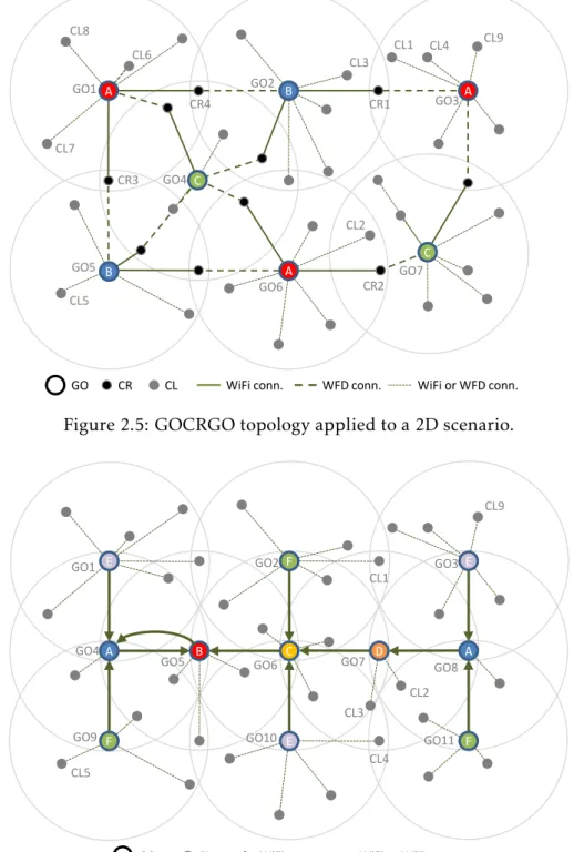
2.5 GOCRGO topology applied to a 2D scenario. . . 25
2.6 GOGO topology applied to a 2D scenario. . . 25
2.7 GOCRGO and GOGO in a 2D grid scenario. . . 26
2.8 Application of GOCRGO topology to a sparse scenario. . . 29
2.9 Application of GOGO topology to a sparse scenario. . . 29
2.10 A crowded scenario with GOCRGO topology. . . 30
2.11 A crowded scenario with GOGO topology. . . 30
2.12 A 3 group scenario in GOCRUCvariant. . . 32
2.13 Experimental scenario for each tested topology. . . 33
2.14 Topologies communication speed. . . 34
2.15 Topology consumed energy. . . 35
3.1 Slave interface connection. . . 44
3.2 Connectivity scenario. . . 45
3.3 Scenario modelled in a UDG and in an AG. . . 46
3.4 An AG modelled scenario not connected by WFD. . . 48
3.5 Running scenario after DNE stage. . . 50
3.6 Running scenario after CLB stage. . . 53
3.7 Running scenario after MCI stage. . . 55
3.8 Running scenario after FCI stage. . . 56
3.9 Connectivity after MCI and FCI stages. . . 63
3.10 Communication results for all stages. . . 63
3.11 Time results for all stages. . . 64
3.12 Cluster interconnections in MCI and FCI stages. . . 65
3.13 MCI interconnection rule applications. . . 66
3.14 FCI interconnection rule applications. . . 66
L i s t o f F i g u r e s
3.16 RedMesh with and without one rule. . . 67
3.17 LCsToGOs results. . . 68
3.18 Rule order results. . . 70
3.19 Connectivity with and without intermediate connections. . . 70
3.20 Scenario not connected with L = 5 and connected with L = 6. . . . 72
3.21 1st scenario connected with L = 5 and not connected with L = 6.. . . 72
3.22 2ndscenario connected with L = 5 and not connected with L = 6. . . . 73
3.23 RedMesh versus MAGNET. . . 75
3.24 Scenarios not connected by RedMesh : 1 and 2. . . 76
3.25 Scenarios not connected by RedMesh : 3, 4 and 5. . . 77
L i s t o f Ta b l e s
1.1 Samsung Galaxy S evolution . . . 2
2.1 Communication assessment . . . 16
2.2 Topologies spatial node requirements. . . 21
2.3 Topologies communication speed. . . 22
2.4 Topologies routing operations. . . 23
2.5 Topologies comparison . . . 31
2.6 Experimental setup. . . 34
3.1 RedMesh cluster interconnection rules. . . 57
3.2 Scenarios metrics . . . 61
Ac r o n y m s
A5C Android 5 Compliant. AG Arbitrary Graph. AP Access Point.
BAS Bonjour Advertising Service. BCF Broadcast Factor.
BCS Broadcast Speed. BLT Bluetooth.
BSF Bluetooth Scatternet Formation.
CIP Cluster Interconnection Procedure.
CL Client.
CLB Cluster Building.
CNG Cluster Neighbourhood Gathering. CR Client Relay.
CSS Candidate Slave Set.
DFS Depth-First Search.
DHCP Dynamic Host Configuration Protocol. DNE Dominant Node Election.
DTN Delay Tolerant Network.
EBO Enslaved By Others Set.
EIP End of Interconnections Procedure.
FCI Final Cluster Interconnection.
GO Group Owner.
AC R O N Y M S
GOCR Group-Owner Client-Relay.
GOCRUC Group-Owner Client-Relay UniCasts.
GOCRGO Group-Owner Client-Relay Group-Owner. GOD Dominant Group Owner.
GOGO Group-Owner Group-Owner.
LC Legacy Client.
LTE Long Term Evolution.
MANET Mobile Ad Hoc Network.
MCF Multipeer Connectivity framework. MCI Main Cluster Interconnection. MIS Maximal Independent Set.
NAN Neighbor Awareness Networking. NoA Notice of Absence Protocol. non-A5C non-Android 5 Compliant.
OPS Opportunistic Power Save Protocol.
PSK Pre-Shared Key.
SGF Smart-Group-Formation. SSID Service Set Identifier.
UDG Unit-Disk Graph.
WFD Wi-Fi Direct.
WFR Wi-Fi Range.
WFS Wi-Fi Speed.
WiFi Wi-Fi.
WPA2 Wireless Protected Access - 2. WPS Wi-Fi Protected Setup.
C
h
a
p
t
e
r
1
I n t r o d u c t i o n
The main research statement of this thesis is“It is possible to build large scale mesh networks of Wi-Fi Direct (WFD) enabled devices”. This statement is decomposed into two: “It is possible to do WFD intergroup connection and communication for large scale mesh networks”
and“It is possible to systematically form WFD large scale mesh networks”.
This Introduction presents the context and all the steps taken along the research pro-cess driven by those statements. It is composed by the following sections: 1.1Context;1.2
Challenges and statements;1.3Proposed solutions;1.4Contributions and1.5Document structure.
1.1
Context
According to Ericsson Mobility Report of November 2017 [22], the number of smartphone subscriptions will increase from 4.4 billion in 2017, to 7.3 in 2023. The same report also unveils that smartphone mobile data traffic will increase from 13.8% to 40% of total data traffic, in the same period. Therefore we can state that smartphones will become ubiquitous and users will become huge data producers and/or consumers.
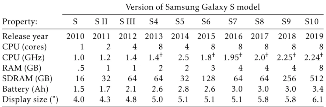
To help this revolution, the capabilities of the hardware of the smartphones continue increasing in every aspect. Table1.1shows the evolution of a well known mobile phone model over the last 9 years. It shows an increase of CPU power by more than 8 times, of main memory by 16 times, and of internal memory by 32 times. Battery power and display area have also increased by factors of 2.2 and 2.3, respectively. Furthermore, nowadays we can find mobile phones equipped with many communication technolo-gies (GSM/CDMA/HSPA/LTE, Wi-Fi 802.11 a/b/g/n/ac, dual-band, WiFi-Direct, DLNA,
C H A P T E R 1 . I N T R O D U C T I O N
Table 1.1: Samsung Galaxy S evolution
Version of Samsung Galaxy S model
Property: S S II S III S4 S5 S6 S7 S8 S9 S10 Release year 2010 2011 2012 2013 2014 2015 2016 2017 2018 2019 CPU (cores) 1 2 4 8 4 8 8 8 8 8 CPU (GHz) 1.0 1.2 1.4 1.4† 2.5 1.8† 1.95† 2.0† 2.25† 2.24† RAM (GB) .5 1 1 2 2 3 4 4 4 8 SDRAM (GB) 16 32 64 64 32 128 64 64 256 512 Battery (Ah) 1.5 1.7 2.1 2.6 2.8 2.6 3.0 3.0 3.0 3.4 Display size (") 4.0 4.3 4.8 5.0 5.1 5.1 5.1 5.8 5.8 6.1 Source: www.gsmarena.com. SDRAM in maximum values.†, in average.
hotspot, Bluetooth, NFC, etc.), sensors (GPS, fingerprint, accelerometer, compass, gy-roscope, proximity, ambient light, barometer, heart rate, SpO2, microphones, etc.) and cameras. This hardware increase confirms the trend of the use of mobile devices to become major players as data producers and/or consumers.
Current smartphone capabilities enable rich consumer interactions over the internet, producing and consuming contents like music, photos, videos or data in general. Such collaborative interactions should not be restricted to the internet, as users may demand to have them even when there are no communication infrastructures (for example, in isolated areas and disaster situations), the communication infrastructure is saturated (such us in crowded venues, as in big sports and cultural events [22, 31, 48]) or when the public network cannot be trusted (like in political demonstrations in countries that censor network traffic or in the event of governmental actions in foreign countries) [58]. Collaborative systems, exclusively based on mobile devices, may not only help to disseminate information (like messages and photos) but also to share resources among users. These systems can act as a mobile cloud for data and computation [34], providing users with the sum of all the connected resources. Real-world examples of applications that can be used in such scenarios include:
• the USA military CBMEN (Content-Based Mobile Edge Networking) program1, aim-ing at “enabling efficient, transparent distribution of content in mobile ad hoc network environments” that will allow soldiers to share information in war scenarios, like
in Figure1.1a1;
• a photo face recognition system to look for missing people in crowded scenarios, to be used like in Figure1.1e2;
• a video sharing system for sport events recorded and watched by in-place fans [12];
1http://www.darpa.mil/program/content-based-mobile-edge-networking, accessed on Jul 26, 2019. 2https://sverigesradio.se/sida/artikel.aspx?programid=83&artikel=7243712, accessed on Jul 26, 2019.
1 . 2 . C H A L L E N G E S A N D S TAT E M E N T S
• a system supporting the exchange of emergency messages in disaster scenarios, to be used like in Figure1.1c3;
• a system supporting the exchange of messages and videos for political demonstra-tions, to be used like in Figure1.1e2;
• a system to enable cave explorers/rescuers to communicate and transfer data, among themselves and to the outside team, to be used like in Figure1.1b4;
• an educational system to enable data exchange for outdoor classes, to be used like in Figure1.1f5; and
• a system for scientists or photographers, connecting mobile phones, sensors, photo cameras, wireless flashes, external disks, offering a kind of a cloud to save and share data and photos, to be used like in Figure1.1d6.
1.2
Challenges and statements
However, the feasibility of such infrastructureless collaborative mobile systems is bound to the ability to interconnect them. In that context, Bluetooth (BLT), Wi-Fi Direct (WFD), WiFi-Aware, MCF and MeshTalk are (or will be) communication technologies that can be used for direct interconnection of off-the-shelf mobile devices. Here we will give a brief description of these technologies.
Before that, we have to clarify that devices may benon-rooted or rooted. Non-rooted
devices are the ones which are in the conditions they are sold. Thus, they keep their manufacturer/seller warranty valid. Rooted devices are the ones which have their
operat-ing system changed outside the manufacturer/seller control and consequently they are out of warranty. Rooted devices may incorporate any software, including a complete new
operating system. Its purpose is to explore the use of the hardware beyond what the operating system from the manufacturer offers. Hence, rooted devices may improve their use, but users usually reject it, as they are not interested in losing the warranty of their phones. Therefore, we only targetnon-rooted, which is off-the-shelf, devices to allow a
general use of the intended device-to-device connectivity that we are looking for.
Bluetooth (BLT)[6] is a technology for device-to-device communication, conceived for devices with few capabilities and reduced battery. Therefore, its communication speed and coverage range are much more restrictive than those of Wi-Fi (WiFi) or WFD. Besides that, there is a lot of work in BLT intergroup communication (named Bluetooth Scatternet
3
https://temblor.net/earthquake-insights/nasa-radar-maps-reveal-massive-extent-of-amatrice-damage-from-italy-earthquake-1271/, accessed on Jul 26, 2019.
4https://svhtt.thuathienhue.gov.vn/?gd=6&cn=1&id=187&tc=2109, accessed on Jul 26, 2019.
5http://jonnelexplorer.blogspot.com/2014/06/mt-telakawa-capas-national-shrine.html, accessed on Jul
26, 2019.
6https://blog.nature.org/science/2019/01/03/what-scientists-can-learn-from-sound-and-silence/,
C H A P T E R 1 . I N T R O D U C T I O N
a: Autonomous military scenario b: Cave scenario
c: Earthquake scenario d: Scientific expedition scenario
e: Crowded scenario f: Outdoor educational scenario Figure 1.1: Scenarios that can require autonomous connectivity
Formation (BSF)) like in [14,28,29,40,41,54,59,60] and, also, recently BLT version 5 specification endorsed BSF in its Mesh networking Specification [3].
Wi-Fi Direct (WFD)[56] is an interesting technology as it may offer device-to-device
communication with WiFi range and speed. It is a WiFi-based protocol that can form groups of devices, where one device named Group Owner (GO) acts as a coordinator of the group, providing advertising and discovery of devices and services, group formation and authentication, Dynamic Host Configuration Protocol (DHCP) and data forwarding services for group members. Nevertheless, as a WFD group can usually support only 8 clients and all of them must be in the GO coverage range, crossing groups is funda-mental for medium and large scale scenarios. The WFD specification does not tackle group interconnection, leaving it open for research. Yet, once built, a WFD multi-group communication network may provide long-range and fast data transfer in scenarios with
1 . 2 . C H A L L E N G E S A N D S TAT E M E N T S
off-the-shelf mobile devices and with no network infrastructure, paving the way for col-laborative systems that can be useful in the situations already mentioned.
WiFi-Aware/Neighbor Awareness Networking (NAN)[1] is a device-to-device tech-nology recently proposed by the WiFi Alliance. It organizes devices in clusters, called
NAN Clusters, sharing parameters like a cluster id, a synchronization clock and a main
master (anchor master). Clusters may merge to form a common cluster. Devices may participate in several clusters, but that is not covered by the specification. Devices may operate concurrently in a NAN cluster and also on WiFi infrastructure or WFD, but that is also not covered by the specification. Communication is based on the WiFi 802.11 physical layer complemented with a NAN MAC layer. Google already defined an API for WiFi-Aware in its Android 8.0 version7and there are now some mobile phones, like Google Pixel 3, with WiFi-Aware certification. Therefore, we conclude that WiFi-Aware is now ready to be tested. However, it cannot be used in large scale scenarios, as: 1) clusters have a single main (anchor) master, which will not be a scalable solution for large clusters; and 2) neither multi-cluster operation, nor concurrent operation with other technology is defined.
There are also the Multipeer Connectivity framework (MCF)8developed by Apple. This technology offers device-to-device discovery and communication, but also over the WiFi infrastructure for iOS or over the internet for macOS. There is no public specification and the on-line documentation only affirms that MCF uses peer-to-peer WiFi (Wi-Fi Direct) and BLT for the underlying transport. It organizes devices, called peers, in groups, called sessions. Sessions can have a total maximum of 8 devices. A peer may be connected to several sessions and may transfer data among sessions. A peer can send/receive data to/from another to peer in a common session. Hence, we conclude that MCF builds on Wi-Fi Direct and BLT and should have their identified limitations for large scale scenarios.
MeshTalkis a device-to-device technology recently announced by the Oppo manufac-turer9. This technology promises to allow device-to-device communication up to 3 Km away, without using cellular networks, WiFi or BLT. They claim that this technology will enable text messages and voices calls, and offer low-power consumption. They also claim that devices will be able to last 72 hours in standby (with MeshTalk active). However, its specification is not available and the technology is, for now, just a promise.
From BLT, WFD, WiFi-Aware, MCF and the possible MeshTalk we can conclude that the mobile reality is moving strongly to enable device-to-device communication and a connectivity solution for large scale is now, or in a near future, a real demand.
From the existing device-to-device technologies, when we had to make the selection, we elected Wi-Fi Direct as it was the one that could provide WiFi range and speed. The
7https://developer.android.com/guide/topics/connectivity/wifi-aware, accessed on Jul 26, 2019. 8https://developer.apple.com/documentation/multipeerconnectivity, accessed on Jul 26, 2019. 9https://www.gsmarena.com/oppo_meshtalk_can_make_calls_and_send_texts_with_no_carrier_or
C H A P T E R 1 . I N T R O D U C T I O N
Aware is now available to be tested, but not ready at that time. Nevertheless, WiFi-Aware needs a solution for large scale scenarios.
Focusing on WFD, the existing work in inter-group communication has several draw-backs as it mainly forms tree like networks, it requires many nodes and transmissions per group and it uses broadcast communication. However, for medium or large scale scenarios, mesh networks offer advantages over tree ones, as they can be built in a dis-tributed way and offer alternative traffic paths, which can reduce the average short path length between devices and enable redundant paths. The main challenges here were: all GOs have the same IP address and devices connected to two groups can only initiate communications through their priority interface.
The meanwhile produced state-of-the-art in network formation algorithms for WFD attempt to build tree networks which are not adequate for large networks or they create mesh networks but with limited connectivity. Besides that, they use communication topologies that use broadcasts, which are slow and energetically demanding. The main challenges here were: to have and select a topology to use; define which nodes to use for interconnection; and how to connect them.
This context motivated the main research question of this thesis:
MQ) “Is it possible to build large scale mesh networks of WFD enabled devices?”.
The answer to the main research question (MQ) raised two base questions:
Q1) “Is it possible to do WFD intergroup connection and communication for large scale mesh networks?” and
Q2) “Is it possible to systematically form WFD large scale mesh networks?”.
However, as a solution using WFD will be the only existing solution for off-the-shelf (non-rooted) devices, the main research question can be framed by the following wider
question:
WQ) “Is it possible to build large scale mesh networks of off-the-shelf mobile devices?”.
1.3
Proposed solutions
To overcome existing challenges, in relation to WFD group interconnection, we devel-oped the Owner Client-Relay Owner (GOCRGO) and Owner Group-Owner (GOGO) connection and communication topologies. They, together, offer comple-mentary ways to cross WFD groups and provide connection for any configuration of nodes. They also accomplish two secondary goals of using only unicast communication and requiring the minimum number of nodes and transmissions per group.
Building from GOCRGO and GOGO topologies, we developed RedMesh , a mesh network formation algorithm for off-the-shelf WFD enabled devices. The conceived al-gorithm defined several cluster interconnection rules, used gateway nodes in a way to
1 . 4 . C O N T R I B U T I O N S
prevent the blockage of possible connections and used a second interconnection round to improve connectivity. With these innovative aspects the algorithm achieved full con-nectivity in 97.28% of the 1250 test case scenarios, with up to 250 nodes. An emulation of the best state-of-the-art algorithm, meanwhile developed, even when added with our innovative aspects, only achieved 84.88% of fully connected scenarios.
1.4
Contributions
This thesis makes the following contributions:
• two communication topologies, named Group-Owner Client-Relay Group-Owner (GOCRGO) and Group-Owner Group-Owner (GOGO), which allow WFD inter-group communication for up to large scale scenarios. The former enables to form mesh like structures and the latter enables to form tree like structures. Both of them use the minimum number of devices and allow the use of unicast communication.
• a secondary communication topology named Group-Owner 2 Client-Relay (GO2CR) and a variant named Group-Owner Client-Relay UniCasts (GOCRUC), which allow
the use of unicast communication, but require more devices than the first two topologies.
• a network formation algorithm, called RedMesh , which defines five cluster inter-connection rules, uses three communication rounds, and manage gateway nodes to increase connectivity.
• the identification of possible improvements in the RedMesh algorithm.
We also produced the following papers in the scope of this thesis:
• Core A, short paper: [49] A. Teófilo et al. “Group-to-Group Bidirectional Wi-Fi Direct Communication with Two Relay Nodes.” In: 12th Int. Conf. on Mobile and Ubiquitous Systems: Computing, Networking and Services. MobiQuitous’15. Coimbra,
Portugal: ACM, July 2015, pp. 275–276. i s b n: 978-1-63190-072-3. d o i: 10.4108/ eai.22-7-2015.2260272
• National conference, full paper: [50] A. Teófilo et al. “Comunicação Móvel Inter-Grupo Baseada em TCP sobre Wi-Fi Direct.” In: 8th INForum - Simp. de Informática.
INFORUM’16. Lisboa, Portugal, 2016
• Core A, full paper: [51] A. Teófilo et al. “GOCRGO and GOGO: Two Minimal Communication Topologies for WiFi-Direct Multi-group Networking.” In: 14th Int. Conf. on Mobile and Ubiquitous Systems: Computing, Networking and Services.
MobiQuitous’17. Melbourne, Australia: ACM, 2017, pp. 232–241. i s b n: 978-1-4503-5368-7. d o i:10.1145/3144457.3144481
C H A P T E R 1 . I N T R O D U C T I O N
Therefore, with the communication topologies and the network formation algorithm created in this thesis, the ground is provided for systems that enable mobile resource sharing without the support of a communication infrastructure. Thus, the way is now paved to create autonomous mobile collaborative applications that can explore the ever increasing capabilities of smart phones.
This work can also be used in hybrid systems that have some parts that require device-to-device communication and other parts that may build bridges to a backbone, either by cable or wireless (Wi-Fi/3G/4G/5G). In [47] one case of such hybrid systems is presented, where, in simulation, data from mobile devices is shared by aMobile Ad Hoc Network (MANET)network supported by the devices and shared by an infrastructure network where it is available. The work in this thesis could offer the background to bind the
MANETused, in the mentioned system, to a real communication support based on the devices without the need to violate their warranty integrity.
1.5
Document structure
The reminder of this document is structured as follows.
Chapter2 covers the research question “Is it possible to do WFD intergroup connec-tion and communicaconnec-tion for large scale mesh networks?”. Firstly, it presents the research
context in WFD intergroup connection and communication, its current solutions and problems. Secondly, it contains our developed topologies for WFD intergroup connection and communication and also their evaluation.
Chapter3covers the research question“Is it possible to systematically form WFD large scale mesh networks?”. It starts presenting the current state-of-the-art algorithms for
WFD network formation and identifies their major problems to support large scale mesh networks. Then it covers RedMesh , our developed WFD network formation algorithm and present its evaluation, its limitations and some reflections about improvements.
Finally, Chapter 4 concludes this dissertation and presents future work and open issues.
C
h
a
p
t
e
r
2
Wi F i - D i r e c t G r o u p I n t e r c o n n e c t i o n
This chapter covers the question“Is it possible to do WFD intergroup connection and com-munication for large scale mesh networks?”.
Section2.1introduces WFD intergroup connection and communication and existing challenges, and presents current solutions and their inefficiencies. Section2.2presents our newly proposed topologies, for WFD intergroup connection and communication, and their evaluation. Finally, Section 2.3exposes our conclusions about the addressed research question.
2.1
Context and problems
Here we present the context and problems in WFD group interconnection and commu-nication. We start with an introduction to WFD in Section2.1.1and then we discuss the problems to support WFD group interconnection and communication in Section2.1.2. Next, we present current solutions and its limitations to achieve WFD group interconnec-tion and communicainterconnec-tion in Secinterconnec-tion2.1.3and conclude the topic in Section2.1.4.
2.1.1 WiFi-Direct introduction
Wi-Fi Direct (WFD) is a technology that enables direct device-to-device communication and is tailored to operate inside groups of devices. Its base services are device, and service, advertising and discovery, group authentication and formation, DHCP and data forwarding services.
Nodes start announcing their presence and trying to discover peer devices. They send probe requests in 802.11 channels 1, 6 and 11, in the 2.4 GHz band, and listen for probes of other devices. Each device elects one of these channels as its listen channel and only
C H A P T E R 2 . W I F I - D I R E C T G R O U P I N T E R C O N N E C T I O N
listen on that channel. They alternate between sending and listening stages, spending on each state a randomly distributed amount of time between 100 and 300 ms.
After device discovery and before group formation, devices may announce their ser-vices and query for peers with specific serser-vices using the Generic Advertisement Service (GAS) (802.11u) [26]. Android devices may use the UPnP and the Bonjour [15] as high level discovery protocols to query for services. In this thesis as we only use the Bonjour protocol we call it: Bonjour Advertising Service (BAS). Devices also use this service to broadcast generic data to spread information to neighbour peers. With advertised in-formation nodes discover their neighbour nodes and their state and they can proceed to group formation.
WFD groups have one node named Group Owner (GO) that acts as a group coor-dinator. This coordinator acts as an Access Point (AP) providing group authentication and formation, DHCP and data forwarding services to the remaining group members. Group formation can be done in three ways:Standard Group Formation, Persistent Group Formation and Autonomous Group Formation.
InStandard Group Formation two devices negotiate an intent value to be GO (a value
in [0..15]) and the one with the highest value is elected. When the intent values are equal, devices use a random tie breaker bit (also sent) and the one with this bit active (generat-ing new random bits if necessary) is the one elected. The elected node then defines the channel where the group will operate, creates an IEEE 802.11 Access Point (AP) and be-comes ready to accept requests, from devices in the neighbourhood, in Wireless Protected Access - 2 (WPA2) [25]. The nodes then go through a Wi-Fi Protected Setup (WPS) [55] phase, establishing a secure connection and where the non-GO device connects by the WFD interface with the GO. Finally, the new client receives a DHCP address and is ready to use group services.
InPersistent Group Formation, devices use group credentials previously stored (from a
past formed group with the involved devices). Hence, this case requires that, once a group is formed, devices save the group credentials and later, on a new connection, the devices will restore the GO and Client (CL) roles and re-stablish the saved group (between them). This possibility saves time, skipping the negotiating phase.
InAutonomous Group Formation, a device autonomously creates a group, becoming a
GO on its own. Then, devices can discover this new GO and connect to it, also skipping the GO negotiation phase.
Once a group is formed, the GO can accept WFD clients, called CLs, but also WiFi clients, called Legacy Clients (LCs), if they know the Service Set Identifier (SSID) and Pre-Shared Key (PSK) of the announced network/group. Normally, GOs can only accept 8 clients. In generic terms we define that value as L and then L = 8. If a GO leaves the group, the group is broken and a new group has to be formed. There is no way of transferring the GO role to another node. All clients of a GO must be in the GO range and all the communication among them goes through the GO, being forwarded by the GO at MAC level. A detailed description of WFD can be found in [8].
2 . 1 . C O N T E X T A N D P R O B L E M S
Now we will analyse the sub-topics of: how to deal with Android WFD user connection approval and WFD characteristics to support multi-groups.
Android WFD user connection approval
Here we approach the practical detail of Android user connection approval. In a GO, the connection of a new client, for security reasons, requires a user approval action.
In this thesis as we would like to connect one device with several others and possibly changing connections over time, we do not want the inconvenience of asking the user for such confirmations. Therefore, to skip the user confirmation we set the GO device in WPS mode (push button method) to accept connections from other nodes (as clients). In this case the Android only shows a notification, but does not require a confirmation. That is not the correct way of doing it, as it weakens the security, but it was done for practical reasons.
This aspect calls for improvements in the Android interface, like having a way of disabling these notifications. Other possible ways are to present them as normal notifica-tions or avoiding them by allowing connecnotifica-tions by sending a PIN or the PSK to the GO and without having to activate the WPS push button method.
WFD characteristics to support multi-groups.
A WFD device can be connected to two WFD groups. It must be a LC in one group and it can be CL or GO in the other group. When a device is connected to two groups it must be active in only one of them at the time. Thus, when a device is inactive in a group, it should notify the group.
The WFD defines two power saving protocols that can be used to suspend the partici-pation in a group. They are the Opportunistic Power Save Protocol (OPS) and the Notice of Absence Protocol (NoA).
The Opportunistic Power Save Protocol (OPS) allows clients to notify the GO that they will go into the inactive state. That allows them to be absent from the group, entering in a power save mode and be active in another group. This protocol also enables the GO to enter in an inactive state when all clients are in that same sate. Therefore, we conclude that this protocol can be used to allow the absence of clients by their own initiative.
The Notice of Absence Protocol (NoA) allows the GOs to notify clients of their absence from the channel (group), regardless of clients being in the active or in the inactive state. Those notifications establish NoA absence schedules using the parameters: delta time to first period, period duration, time between periods, and number of periods. A schedule can be cancelled or updated any time, with new notifications. Thus, we conclude that this protocol can be used to allow GOs absence by their own initiative.
We then conclude that WFD has the means to coordinate devices inside and among groups.
C H A P T E R 2 . W I F I - D I R E C T G R O U P I N T E R C O N N E C T I O N
2.1.2 Group interconnection challenges
WFD specification does not tackle group interconnection, leaving this functionality open for research. Here we will see the challenges to connect two GOs directly and indirectly. Two GOs can be connected directly if one connects its WiFi interface to the other. However, GOs usually have the same IP address (192.168.49.1/24) in the WFD interface and lower level communication layers eliminate packets from, or to, any address that is considered local. Therefore, two connected GOs will not be able to communicate directly using that address, as it is simultaneously a local and the destination address and that causes address conflict.
Two GOs may be connected indirectly by using a node as middle-point. That node should connect its WiFi and WFD interfaces to the GOs and is called a gateway or Client Relay (CR). Normally, it will not be able to address nodes from the groups of both GOs, as they all share the same network address 192.168.49.x/24. In these cases, the Android platform directs all packets to one interface, thepriority interface. Consequently, relay
nodes cannot normally initiate communications through theirnon-priority interface.
To make matters worse, thepriority interface behaviour is not uniform. Some devices
have WiFi aspriority interface (e.g. Nexus 7), others have WFD (e.g. Nexus 5X, 6, 6P and 9)
and others only support one active interface at a time (e.g. Motorola G2 2nd generation). Also, Duan [13] and Casetti [10] reported that when devices have WiFi as their pri-ority interface, broadcasts are sent out by both interfaces (WiFi and WFD). However, the
opposite is not true, as we observed (in Nexus 6, Nexus 9 and OnePlus One) that when WFD is thepriority interface, broadcasts are not sent by the WiFi interface.
With these difficulties, most of past WFD work focused on dealing with a single group or using a second communication technology or intermittent connections to cross WFD groups.
2.1.3 Group interconnection current solutions
To cross WFD groups we can use intermittent or permanent connections, as well as other technology. In Section2.1.3.1we discuss existing work when using another technology or intermittent connections. The use of permanent WFD connections is the most interesting solution as it offers WiFi speed and range, if devices can operate with both interfaces simultaneously and in an independent way. To the best of our knowledge, the only solution to offer WFD intergroup communication over persistent connections is from Duan et al [13], which is presented in Section2.1.3.2.
2.1.3.1 Interconnection with no permanent connections
Inside one WFD group we identified the following works: Menegato et al [7] and Demir et al [11] proposed GO election schemes to form a group of WFD devices; Funai et al [18] proposed a task distribution system, using WFD to interconnect five devices in a WFD
2 . 1 . C O N T E X T A N D P R O B L E M S
group; Mao et al [33] studied data transmission strategies with three devices, inside one WFD group; Penner et al [39] formed a cloud with WFD group with three devices, to share tasks among devices; Pozza et al [42] used WFD to spread internet data through one WFD group, using several sharing schemes and comparing with BLT; and Rodrigues et al [44] benchmarked content dissemination in several wireless configurations, one of them was inside one WFD group.
One possible solution to cross WFD groups is to use a second technology. In these cases, WFD communication occurs just inside one group. Using Long Term Evolution (LTE) or Bluetooth (BLT) to communicate between WFD groups or with WFD groups and some internet service provider, we identified the following works. Asadi et al [2] connected three WFD groups with mobile LTE, they use groups with ten members but only in simulation; Pyattaev et al [43] analysed LTE traffic offloading onto WFD devices
to share data inside WFD groups; Trestian et al [52] analysed energy consumption in multimedia data delivery comparing LTE, WFD and BLT, used one WFD group with one GO and one CL and their tests showed that WFD required less energy to transmit and receive data than BLT; and Gong et al [21] proposed a video streaming system, by enabling a WFD group of three devices to access a video server connected by LTE.
Some works use the WFD Generic Advertisement Service (GAS) to spread data in an augmented group of nodes. Marinho et al [35] implemented a routing messaging scheme over GAS, which became saturated with only 6 devices; and Shahin et al [46] proposed an alert dissemination protocol over GAS.
Nevertheless, the use of a second technology has the drawback of losing the WFD benefits of speed and range.
Besides that, Jung et al [30] proposed a self-organizing multi-group WFD network based on data location. However, they work in simulation and did not approach the limitations of WFD multi-group communication.
Delay Tolerant Networks (DTNs) [53] are networks where one device interconnects two WFD groups, but to transfer data, it connects to one of them at a time. DTNs enable intergroup communication, but require buffering and impose delays in data delivery. Example of works with WFD DTNs are: Hoang et al [23]; Felice et al [17]; Mizumura et al [36]; Funai et al [19,20]; and Wong et al [57]. As Android allows multicasts to be sent by a specific interface, Funai et al [20] extended the DTN model, using multicasts to control the connections and the direction of the communications. Nevertheless, multicasts are almost as slow as broadcasts.
In summary, the address conflict and the priority interface limitations turn WFD intergroup communication in a non simple task. Presented solutions confirm that, as they use WFD but cannot make full use of WFD capabilities for intergroup communication.
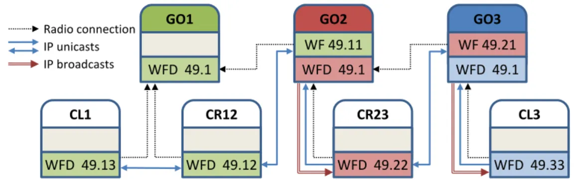
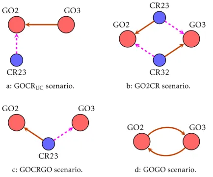
C H A P T E R 2 . W I F I - D I R E C T G R O U P I N T E R C O N N E C T I O N GO2 WF 49.11 WFD 49.1 GO3 WF 49.21 WFD 49.1 CL1 WFD 49.13 IP unicasts Radio connection IP broadcasts GO1 WFD 49.1 CR12 WFD 49.12 CR23 WFD 49.22 CL3 WFD 49.33 Figure 2.1: A 3 group scenario in GOCR topology.
GO nodes have identification and colour in top section. All nodes have, in their two lower sections, the IP and colour of the destination GO for WiFi and WFD interfaces, when connected.
Similar scenarios use these features.
2.1.3.2 Group-Owner Client-Relay (GOCR) topology
TheGroup-Owner Client-Relay (GOCR) topology, proposed by Duan et al [13] and Casetti et al [10], enables direct GO connection. GO nodes connect their WiFi interface to the next GO, although they do not communicate directly. They use a client as an auxiliary node, which acts as a relay node (CR) to avoid the address conflict. To enable communication by thenon-priority interface, GO nodes use broadcasts. This work assumes WiFi as the priority interface.
To provide a global perspective, Figure2.1presents a three group scenario using this topology. In this figure, and in similar ones, nodes contain identification and addresses in WiFi and WFD interfaces. To keep figures and text clear enough, addresses are only mentioned by their last two octets.
Figure2.1also shows interface radio connections (in black dash arrows), UDP unicasts (in blue solid arrows) and UDP broadcasts (in red double arrows). Communications will go over the established radio connections. In terms of message path and using GO2 to GO3 as an example, from GO2 to GO3, GO2 sends a broadcast to CR23 and this one relays the message in a unicast to GO3. CR23 can address GO3 because both are GO2 clients. The last message is addressed to 49.21 and packets are forwarded by GO2 at MAC level. In the opposite direction, GO3 sends a unicast to the CR23, which resends it in another unicast to GO2. GO3 can address CR23, as they are both GO2 clients and packets are sent by GO3priority interface (the WiFi interface). Furthermore, communication will
go from 49.21 to 49.22 without any conflict of address.
The relevant points in this topology are that GOs connect directly but communicate through one relay (CR) node and GOs must broadcast data to their CRs.
IP messages between CRs and the next group GOs are forwarded at MAC level by the GO of the CR, resulting in 2 MAC messages over the channel of the GO. We conclude that GOCR requires: 2 nodes per WFD group (1 GO and 1 CR) and per additional Wi-Fi Range (WFR)1, and 3 MAC messages to cross a WFD group in each direction. It needs
2 . 2 . S O LU T I O N S A N D R E S U LT S
broadcasts and also 3 routing operations (2 by GOs and 1 by CRs) in each direction. This topology, to have all nodes interconnected, forms tree like networks, as each GO should connect its WiFi interface to another GO that is not its client or part of the networks of its clients. The tree top GO will be the only node with a free WiFi interface, which can be connected to any node. Nevertheless, it will not be enough to create a true mesh network.
2.1.4 Conclusion
This section showed that crossing WFD groups is not currently done in a way of poten-tially achieving WiFi speed and range. From all solutions, only GOCR topology goes in what we identify as the best direction: the simultaneous use of WiFi and WFD interfaces. Nevertheless, it presents many inefficiencies, namely requiring broadcasts, many nodes, data transmissions and routing operations per group and can only form tree networks. Therefore, it creates the opportunity and motivation to find topologies to use in WFD mesh networks that only communicate by unicasts.
Thus, we conclude that the question“Is it possible to do WFD intergroup connection and communication for large scale mesh networks?” is an open research question.
2.2
Solutions and results
Here we present the developed solutions and their results to address the question“Is it possible to do WFD intergroup connection and communication for large scale mesh networks?”.
In Section2.2.1we present our proposed topologies for WFD group interconnection. In Section 2.2.3we evaluate existing and newly proposed topologies. Finally, in Sec-tion2.2.4we present our conclusions about WFD group interconnection.
2.2.1 Proposed group interconnection topologies
To create large scale networks it is necessary to have non-GO nodes that connect their WiFi and WFD interfaces to distinct groups. This solves the interconnections of LC2 -GO and LC-LC, assuming that one LC will turn into a -GO. The -GOCR topology may complement these configurations providing interconnection for GO-GO.
Besides the LC-GO interconnection, we have the secondary goal of conceiving e ffi-cient topologies that use unicasts, a minimum number of nodes per WFD group and a minimum number of messages and routing operations to cross WFD groups.
With these goals, we present three new topologies that may rely only on unicasts: the Group-Owner 2 Client-Relay (GO2CR) topology [49], which needs two CRs between GOs for LC-GO interconnections; theGOCRGO topology [51] which needs just one CR between GOs for LC-GO interconnections and theGOGO topology [51] that allows direct
C H A P T E R 2 . W I F I - D I R E C T G R O U P I N T E R C O N N E C T I O N
Table 2.1: Communication assessment
GO1 —WFDCRWiFi— GO2 GO4WiFi.41— GO5WiFi.51—.61WiFiGO6 GO1 ↔ CR CR ↔ GO2 GO4 ↔ GO5 GO5 ↔ GO6 GO4 ↔ GO6
→ ← → ← → ← → ← → ←
TCP 3a 3a 7j 3c 7 7 7 7 7 7
UDP 3a 3a 7j 3d 7 .41f .61g.51g 7 7
T/U-WF – 7 3b – .51e 7 .61h.51h .61i .41i
T/U-WF: TCP and UDP sockets bound to WiFi interface
unicast communication between GOs in GO-GO interconnections. We also developed a variant of GOCR topology that only needs unicast communication.
All our developed topologies enable the exclusive use of TCP channels or UDP uni-casts between nodes.
Now we will present the communication assessment that enables us to develop the topologies. After that we present the topologies.
2.2.1.1 Communication assessment
Android 5.0 (API 21) introduced the capability of binding TCP sockets to a specific interface, being the feature extended to datagram sockets in Android 5.1 (API 22). So, with Android 5 Compliant (A5C) devices it is possible to create sockets that force traffic out through a specific interface, circumventing thepriority interface. Given this context,
we will assess which communication possibilities are available to A5C and non-A5C
devices using their WiFi and WFD interfaces. Table2.1lists the communication behaviour in two cases: two GOs interconnected by a relay node; and three GOs. Both cases were tested with Nexus 6, Nexus 9 and OnePlus One devices, all with WFD aspriority interface.
Table addresses just mention the last octet and they are mentioned only when they are not obvious. In the first line of the table, the addresses mentioned are the ones in the WiFi interface of each node. The addresses mentioned, in other lines, are the destination addresses used in the messages/datagrams. As UDP broadcasts and multicasts have slow communication speed, they are not used in the proposed topologies and are omitted from the table. Nevertheless, broadcasts can only be sent via WFD interface, while multicasts can be sent by both interfaces (if bound to the interface).
We begin by analysing the case of a CR in between GOs: case GO1-CR-GO2 in the table. On the CRpriority interface side, both the CR and the GO1 can send UDP datagrams
or create TCP sockets to the other (3a). On its non-priority interface side, the CR can
communicate with the GO2 by sending UDP datagrams or creating TCP sockets if bound to the WiFi interface (3b). However, binding sockets to the WiFi interface is only available in A5C devices. If CR is anon-A5C one, it has to wait for a TCP connection coming from
GO2 (3c) and leverage on the bi-directional nature of that connection. Although GO2 could send UDP datagrams to the CR (3d), the CR could not answer in the same protocol.
2 . 2 . S O LU T I O N S A N D R E S U LT S
We move now to the analysis of GO to GO communication in case GO4-GO5-GO6 in Table2.1. We start by assessing the situation of GO4-GO5, where GO4 is a client of GO5. As these GOs have the same IP address (192.168.49.1), they cannot communicate, between them, using that address. Ergo, to communicate, these devices must send the data addressed to the IP address, on the WiFi interface, of the other node: cases (.41f) and (.51e). The former (.41f) is only possible because, unlike TCP, the UDP stack, at GO4, does not eliminate packets coming from an IP address that is also local (.1). The latter (.51e) requires GO4 to create a unicast socket bound to its WiFi interface and direct all communication (TCP or UDP) to the address in WiFi interface of GO5. This enables: a) sockets to link to the correct interfaces, and to have a source address other than .1 (.41, in this case) needed for TCP; and b) to have a destination address also other than .1 (.51, in this case). The downside is that, to enable WiFi bounded sockets, GO4 must be an A5C device. In summary, data exchange between a GOCL(GO4) that is a client of another GOGO(GO5) is only possible if the GOCL is an A5C device and the GOGO has its WiFi
interface connected. In that case, GOCLcan create a TCP connection to GOGO, or both of
them can use UDP datagrams.
Now we assess the GO5-GO6 connection. In this case GO5 and GO6 are both inter-connected by their WiFi interfaces, and can communicate directly with UDP (.61g, .51g) or using UDP or TCP with sockets bound to WiFi (.61h, .51h), if they are A5C devices. All those sockets or datagrams must be directed to the IP address on the WiFi interface of the destination device. Lastly, GOs that are clients of one common GO, as GO4 and GO6, can communicate using UDP or TCP sockets bound to the WiFi interface and linked (addressed) to the address on the other GO WiFi interface (.61i, .41i).
In conclusion, it is possible to communicate, using UDP or TCP unicasts: (i) between GOs connected by a CR, if the CR is an A5C device or if it receives a TCP connection from itsnon-priority interface; and (ii) between GOs, if both are in the same network, if they
have the WiFi interfaces connected, and, also, if the one that is client is an A5C device.
2.2.1.2 Group-Owner 2 Client-Relay (GO2CR) topology
In [49], we proposed theGroup-Owner 2 Client-Relay (GO2CR) topology, which
intercon-nects a pair of GOs using two CRs. For that purpose CRs must connect their WiFi and WFD interfaces, to the GOs, in a symmetrical way and each CR will only forward data from thenon-priority interface to the priority interface. Consequently, CRs will send data
only through theirpriority interface, and so they can depend only on unicast
communica-tion.
Figure2.2depicts the radio links (by WiFi and WFD interfaces) and communication paths, in a three WFD group scenario using this topology. likewise in [49], due to the characteristics of the devices used in tests, we consider WFD as thepriority interface in
Figure2.2, here and in the remainder of this document.
C H A P T E R 2 . W I F I - D I R E C T G R O U P I N T E R C O N N E C T I O N GO1 WFD 49.1 GO2 WFD 49.1 IP unicasts Radio connection CL1 WFD 49.13 CR21 WF 49.22 WFD 49.12 CR32 WF 49.32 WFD 49.24 CR23 WF 49.23 WFD 49.31 CR12 WF 49.11 WFD 49.21 CL3 WFD 49.33 GO3 WFD 49.1
Figure 2.2: A 3 group scenario in GO2CR topology.
use itspriority interface (WFD interface) to send unicasts directly, at IP level, to the next
CR, being relayed at MAC level by the intermediary GO. Consequently this topology: needs an average of 1.5 nodes per WFR, as it needs 1 GO and 2 CRs per 2 additional WFRs; needs 2 hops (data transmissions and routing operations) to cross 1 WFD group; can use onlyunicasts; and enables to form mesh networks.
This topology can be used by devices with WiFi as thepriority interface. It should be
applied the same rule: CRs symmetrically forward data from thenon-priority interface to
thepriority interface, which in this case is from the WFD interface to the WiFi interface.
2.2.1.3 Group-Owner Client-Relay Group-Owner (GOCRGO) topology
In [50,51] we proposed theGroup-Owner Client-Relay Group-Owner (GOCRGO) topology,
that interconnects a pair of GOs using only one CR. The CR device will connect to the adjacent GOs using its WiFi and WFD interfaces.
In this topology, CRs have no problems creating TCP sockets or sending UDP data-grams from their priority interface side. But from the non-priority interface side, CRs
cannot create any kind of socket without resorting to the features of Android 5. Yet, lev-ering on the bidirectional nature of TCP connections, if a node from that side establishes a TCP connection to the CR, the CR can use that connection to send data to that side.
Figure2.3showcases the use of this topology, resorting only to the TCP protocol. It uses TCP connections from CL1 to CR1249.11 (meaning address 49.11 in CR12), from
CR12 to CR2349.23, and from CR23 to CL349.33 or from CL3 to CR2349.31, which will enable communication between CL1 and CL3. Communication from the CRs with the GOs is also possible, if for example each GO creates TCP connections to connected CRs. Furthermore, if CRs are A5C devices, it is also possible to communicate using only UDP datagrams.
To conclude, this topology needs an average of 1 node per WFR (1 GO and 1 CR per 2 WFRs) and needs 2 MAC messages and 2 routing operations to cross a WFD group. It can only resort to unicasts and can form mesh networks.
2 . 2 . S O LU T I O N S A N D R E S U LT S GO1 WFD 49.1 GO2 WFD 49.1 TCP connection establishment Radio connection CL1 WFD 49.13 CL3 WFD 49.33 GO3 WFD 49.1 CR12 WF 49.11 WFD 49.21 CR23 WF 49.23 WFD 49.31
Figure 2.3: A 3 group scenario in GOCRGO topology.
This topology can be used directly by devices with WiFi aspriority interface. With
non-Android 5 Compliant (non-A5C) devices, each CR should receive a TCP connection from itsnon-priority interface interface. In Figure2.3, considering WiFi aspriority interface, we
can create TCP connections from CL3 to CR2349.31, from CR23 to CR1249.21 and from
CR12 to CL149.13(or from CL1 to CR1249.11).
2.2.1.4 Group-Owner Group-Owner (GOGO) topology
In [50, 51] we also proposed the Group-Owner Group-Owner (GOGO) topology, which
enables direct GO-GO connection and communication. This topology has the goal of being more efficient than GOCR topology.
In this topology3, GOs must have their WiFi interface connected to another GO. To communicate by TCP, a GO, connected by WiFi to another GO, can establish a channel (socket) to the other but it must go out by WiFi interface, requiring an A5C device. The channel must target the address in the WiFi interface on the other GO. This last require-ment avoids the conflict of address and can be used because nodes decode that address as a local one. Having a TCP channel created, which is bidirectional, both nodes can exchange messages. To communicate by UDP, a GO (GO1), connected by WiFi to another GO (GO2), the first one (GO1), if it is an A5C device, can send unicasts from the WiFi interface (non-priority interface) to the second (GO2), if they are addressed to the WiFi
address of the second (GO2). In the same scenario, GO2, if it is an A5C device, can send UDP unicasts to GO1 if sent from the WFD interface (priority interface) and targeted to
WiFi address of GO1. These UDP unicasts are not suppressed by the Android/Linux communication layers. GO1 like nodes, must be A5C devices to allow UDP unicasts to be sent through thenon-priority interface.
Figure2.4depicts the use of this topology in a 3 group scenario. It can be seen that all GOs have the WiFi interface connected, offering an alternative IP address, other than 49.1, to avoid conflicts of address. For data communications we use the notation “Di
Ea”4to denote a data transmission from device D, bound to interface i, to address a of device E. If i is omitted, it means that transmission uses priority interface or the only connected interface. As now expected, transmissions bynon-priority interface must be bound to that interface.
3By default, we consider WFD aspriority interface. 4To make it simple, addresses only mention the last octet.
C H A P T E R 2 . W I F I - D I R E C T G R O U P I N T E R C O N N E C T I O N GO1 WiFi 49.51 WFD 49.1 GO2 WiFi 49.167 WFD 49.1 GO3 WiFi 49.241 WFD 49.1 IP unicasts Radio connection CL1 WFD 49.13 CL3 WFD 49.33
Figure 2.4: A 3 group scenario in GOGO topology.
In that scenario, a UDP communication from CL1 to CL3 follows path CL1 GO1.1, GO1WiFi GO2.167, GO2 GO3.241, and finally GO3 CL3.335. In turn, a
communica-tion from CL3 to CL1 follows the path CL3 GO3.1, GO3 GO2.167, GO2 GO1.51, and finally GO1 CL1.136.
To use TCP, between CL1 and CL3, we can establish the following bidirectional con-nections: CL1 GO1.1, GO1WiFi GO2.167, GO2WiFi GO3.241 and finally GO3
CL3.33.
Consequently, this topology needs 1 node per WFR, and needs 1 MAC message and 1 routing operation to cross a WFD group. It can also only resort to unicasts and it forms tree like networks (like GOCR).
If GOs have WiFi as thepriority interface, and even if devices are non-A5C, each GO
can create TCP sockets from its WiFi interface to the WiFi address of next GO, allowing bi-directional communication between them. In Figure2.4we can create the following TCP sockets (or paths to UDP datagrams): GO1 GO2.167; GO2 GO3.241; and GO3 GO2.167. Furthermore, GO2 can create UDP sockets to GO1.51, but only if bound to the WFD interface (A5C property). Therefore, this topology, with WiFi as the priority interface, can use TCP connections with no restrictions, but needs A5C devices to allow
UDP communication.
The GOGO topology is better than GOCR in every aspect, except that it requires A5C GOs while GOCR does not impose any restrictions. We present a detailed compara-tive analysis between all four topologies (GOGO, GOCR, GOCRGO and GO2CR) in the immediate section (2.2.2).
2.2.2 Topologies analysis
In this section we perform a comparative analysis of the proposed topologies (GO2CR, GOCRGO and GOGO) and the current state-of-the-art topology (GOCR) concerning their spatial node requirements, communication speed, routing demands, frequency usage, network redundancy, connection flexibility and behaviour in extreme situations.
5Path can be shortened in 1 hop by either: GO1
WiFi GO3.241; or GO2WiFi CL3.33.
6Path can be shortened in 1 hop by either: CL3 GO2
2 . 2 . S O LU T I O N S A N D R E S U LT S
Table 2.2: Topologies spatial node requirements.
Topology #GOs #CRs Range (in WFRs) #nodes/WFR
GOCR 1 1 1 2
GO2CR 1 2 2 1.5
GOCRGO 1 1 2 1
GOGO 1 0 1 1
#GOs and #CRs columns contain the nodes per additional group, which extends the range by the value in the Range column.
Spatial node requirements
We begin by analysing the node density (the number of nodes) imposed by each topology. For that purpose, we consider the conceptual measure Wi-Fi Range (WFR), which denotes the maximum coverage distance of a WiFi (and WFD) radio for a mobile device.
GOCR topology requires 1 GO and 1 CR per additional WFD group, which extends the coverage range by WFR, giving 2 nodes per WFR. GO2CR topology requires 1 GO and 2 CRs per additional group, extending the coverage range by 2 WFRs, giving an average of 1.5 nodes per WFR. GOCRGO topology requires 1 GO and 1 CR per additional group, extending 1 WFR, giving an average of 1 node per WFR. Lastly, GOGO topology requires 1 GO per additional group, extending 1 WFR, giving 1 node per WFR. This information is summarized in the Table2.2.
We, then, conclude that the GOGO and GOCRGO topologies present the best average values for #nodes/WFR. Among them, GOGO provides the best radio coverage as it builds only on GO nodes.
Communication speed
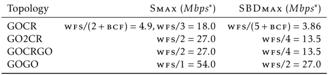
We now want to assess the maximum communication speed in one direction, while in the presence of bi-directional simultaneous communications. For our analysis we make three assumptions: i) GOs operate on independent WiFi channels without any interfer-ence; ii) devices can communicate simultaneously on both interfaces; and iii) for sake of simplicity, we make the rough approximation of considering the same speed for TCP and UDP communications. We consider the following conceptual measures/terms:
Wi-Fi Speed (WFS) – the unicast maximum communication speed in WiFi (and WFD);
Broadcast Speed (BCS) – the maximum broadcast speed;
Broadcast Factor (BCF) – the factor between the maximum unicast and the broadcast speed (BCF = W FS/BCS);
S m a x – the maximum communication speed in one direction, when the topology is used in a single direction; and