SAFETY VERIFICATION IN NON-LINEAR ANALYSES
THE PROBLEM WITH 2
NDORDER EFFECTS EVALUATION
João Vinagre
Director of Escola Superior de Tecnologia do Barreiro of Polytechnic Institute of Setúbal, PORTUGAL Assistant Professor, IST, Technical University of Lisbon;
Keywords: 2nd order effects, non-linear analysis, safety formats
1 INTRODUCTION
This paper discusses the various methodologies that are usually applied for the safety verification of reinforced concrete structures, when adopting non-linear analyses and is based on the studies performed by the author [1]. This verification is linked to securing a minimum collapse probability of structures, which may be calculated in an explicit way (by correctly modelling the structure, all actions and materials, taking into account the stochastic nature of all involved variables) or performed indirectly, by using partial safety coefficients.
In the next paragraphs, the different techniques usually adopted are briefly explained. The difficulties involved in adopting safety coefficients for actions are discussed and the major objectives of their application are defined. The associated difficulties are illustrated and the way to avoid them is discussed.
In respect to the application of safety coefficients to concrete and steel, the major methodologies are presented: global safety coefficients applied to the cross sections’ resistance or distinct partial safety coefficients for both materials. The advantages and disadvantages of both models are referred to and an illustration is given based on simple examples. The rules of the most important European codes are also referred, as they reflect the major current opinions on this subject.
2 SAFETY FORMATS
In the modern structural reliability theory, it is accepted that no absolute safety guarantee can be achieved for any structure, some collapse risk having to be accepted. The main objective of structural design thus consists in assuring, within an acceptable level of probability, that the structure (total or partially) maintains its capacity to correctly function and resist when subject to all actions.
In general, one can say that structural safety is directly related to three entities: the actions that are exerted upon the structures, the structure’s behaviour (directly connected to the materials used) and the probability of collapse. The safety verification of a given structure is a complex problem due to the interconnection and interdependency of all those factors.
Since unfavourable limit states are likely to occur during the lifetime of a structure, the safety estimation of the selected structural system is made by means of two processes that may be considered as independent:
• determination of the probabilistic characteristics of the actions and of the geometrical and mechanical properties of the structure — probabilistic analysis of structures;
• quantification of the probability that certain structural states, beyond which the structure is considered to be unable to fulfil its function, are exceeded — reliability of structural systems. After selecting the structural form that is best adapted to the goals envisaged, it is necessary to design its various structural elements. Since this process depends on the actions that are exerted upon the structure and on the characteristical behaviour of the materials involved (resistance, deformability, etc.), it is necessary to establish the relations between them and the elements’ stresses. In hiperstatic structures the design process becomes an indirect one and there are two ways of comparing actions and resistance: by means of transforming actions in actions effects or by transforming resistance in resistant actions (the first process is usually adopted)
Once the design process is established and the action effects on all structural elements are known, it is necessary to perform the safety verification. The first step of this verification is to identify all variables (quantities and parameters) that can satisfactorily describe the uncertainties related to this process: physical, statistical and model uncertainties. Physical uncertainties, like loads, material properties and elements’ dimensions, present a variability that can be described in terms of probability distributions or by means of stochastic processes. This physical variability originates an uncertainty known as physical uncertainty, which can only be quantified by a sample analysis. But the sample
dimension is always limited, which creates a kind of uncertainty called statistical uncertainty. Physical variability modelling involves the selection of an appropriate distribution and the determination of its parameters. These parameters can themselves be considered as uncertainty amounts and will depend on the dimension of the sample (this statistical uncertainty arises from the lack of information associated to the sample’s dimension). The third kind of uncertainty — model uncertainty — is due to the fact that structural design and structural analysis are based on mathematical models that relate, for example, load intensities to load effects (stresses, stress resultants, etc.). However, in some cases it is only possible to make a fair estimation of that relation. The response of usual structures therefore includes an uncertainty component that adds to other uncertainties (physical and statistical). Model uncertainties occur as a result of simplified hypothesis, unknown variable effects, etc. Model uncertainties have strong effects on the structural reliability and should not be disregarded (Thoft--Christensen [2], Ferry-Borges [3]).
Once the uncertainty types have been identified, structural safety can be operated at three levels that differ from each other according to the kind of calculations performed and the accepted approximations. Level 3 constitutes an exact or regulating level, where the collapse probability is explicitly calculated (analysis methods based on the probabilistic distribution knowledge of all basic variables). The main difficulty associated to this safety verification level is the large amount of variables involved and the correspondent vastness of the samples to be analysed (Eibl [4], Henriques [5]).
At level 2, collapse probability is calculated either by means of approximate methods or indirectly, by changing the multidimensional problem into several unidimensional ones (Veneziano [6]). Finally, at Level 1, actions and resistances are represented by characteristic values and are compared by expressions that include partial safety coefficients. The main reason for adopting partial safety coefficients as opposed to global safety factors is that only those can lead to reasonable and consistent reliability standards (Thoft-Christensen [7]). The safety format usually used for reinforced concrete structures is included in this category. The safety verification models involve the comparison of fairly reduced values of the capacity resistance of the elements (the capacity resistance determination is carried out on the basis of the resistance values of the materials design) and actions combinations values, obtained through combinations rules that include the characteristic action values.
3 PARTIAL SAFETY COEFFICIENT FOR ACTIONS
In order to design a structure for a particular set of actions with different types (with distinct occurrence probabilities, different variations in time and space, etc.) it is necessary to establish rules for actions combination.
The study of structural safety for action combinations is very important from a practical point of view because of the significant savings obtained if the right coefficients are chosen. It requires the consideration of the following aspects: probabilistic definition of actions according to their variability in time, space and from structure to structure; transformation of the action probability distributions in probability distributions of actions-effects; resistance probabilistic distribution expressed through several variables and collapse probability calculation.
Simplified rules enabling the combinations of actions are derived from the results obtained. The combinations of actions are obtained through the characteristic values of all different actions that act on the structure by means of equations like the following one:
(1) + + =
∑
∑
≠ i Gi i Qk k j k kj j dk S G Q Q S γ γ ψwhere Sdk is the combination value of action k, considered the main varying action, Gi is one of the permanent actions, Qk the varying action in study and γ the safety coefficients.
The safety format adopted in the current design project, results from the type of structural analysis usually applied. The stress resultants acting on all elements’ cross sections are calculated by means of an elastic analysis of the structure where all acting actions affected by a safety coefficient are considered. Simultaneously, the safety coefficient takes into account the action intensity variability and the errors associated to the design model — design model uncertainties, as well as uncertainties in the action effects model and/or in the resistant model. For the verification of cross sections (design), non-linear constitutive laws, reduced by a safety coefficient that takes into consideration the variability of the material properties, are adopted for the materials.
Since the collapse probability (where collapse means achieving a certain limit state) is the basis of any safety format for structural design, it is possible to establish a minimum value for it, depending on the adopted safety coefficients. This safety format presents the advantage of leading to resistant stress resultants that are independent from the design stresses, as a result of adopting different behaviour laws, and the calculation process does not require any iterations. The major inconvenient is that it does not constitute a consistent format (the extensions obtained in the stress calculation, assuming an elastic behaviour, are in no way related to those associated to the cross section design, as referred by Eibl [4]).
However, when performing a non-linear analysis, the position of the safety coefficients applied to actions is not irrelevant. The results are different whether the coefficient is applied to the actions or to their effects. It is important to notice that, in an automatic computer program that has been developed to perform a structure’s behaviour global analysis, the application of even a single safety coefficient to action effects is problematic. When adopting this process, it is difficult to achieve the necessary equilibrium between internal stress resultants and applied forces, without disturbing the calculation processes (convergence problems).
Although the application of safety coefficients to actions raises some particular problems, the main questions concern the introduction of coefficients that reduce the material’s properties, in particular as regards to concrete.
4 MATERIALS SAFETY COEFFICIENTS
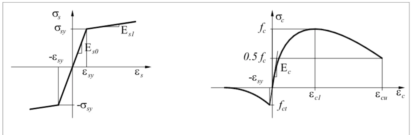
The constitutive laws usually adopted for steel and concrete, when using linear elements, are represented in figure 1. The constitutive law of concrete refers to short duration loads.
ε
syε
s-σ
syσ
syσ
s-ε
syE
s1E
s0 ctf
sy-ε
c1ε
ε
cσ
cE
c cuε
f
c0.5 f
cFig. 1 - Materials stress-strain diagrams and defining parameters: a) steel; b) concrete.
The stress-strain diagram for reinforcing steel is defined by yield strength, fsy, and by the modulus of elasticity, Es. An inclined top branch after yielding can be accepted. Due to minor scattering of the correspondent values, a safety coefficient, γs, of 1.15 is usually adopted.
Concrete relationship is defined by the origin tangent elasticity modulus, Ec, by maximum compres-sion strength, fc, and by the compressive strain in the concrete at the peak stress, ec1. These entities can be considered as independent. The variability presented by origin tangent elasticity modulus and by maximum compression strength has a significant impact on the cross-sections’ stiffness and, therefore, on the calculation of the acting stress-resultants and on the structural deformability (this effect is all the more important as the structure is more susceptible to second order effects).
For safety verification purposes, it is necessary to establish the values that are to be adopted for those entities and the safety coefficients that are going to be considered in the analysis, in order to obtain spinnable results. Possible unfavourable deviations of the applied materials, in relation to the specified characteristic values (resultants, for example, on material’s production, transportation or placement) as accidental deviations or possible local deficiencies in the materials or elements, as a result of fabrication or the execution’s process, will have to be considered.
Once the characteristic values that define the material constitutive law (usually obtained by standard laboratory tests) are established, it still is necessary to apply a correct safety format, obtained through the introduction of safety coefficients.
- non-linear analysis performed with medium or characteristic values followed by the application of safety coefficients to the obtained stress resultants and deformations;
- non-linear analysis performed with constitutive relationships affected by safety coefficients. It should be referred that the Portuguese design code (REBAP [8]), although advising the adoption of non-linear analysis in some situations (important second order effects), does not specify which model should be used. The more recent codes MC90 [9] and EC2 [10] already establish some design methods for this type of analysis that differ from each other. As we will try to explain in the next paragraphs, although formally acceptable, the application of such methods is sometimes questionable. 4.1 Global coefficients
The North American Code, ACI [11], adopts the global coefficient format for ultimate limit states. According to this code, the section’s resistant capacity is calculated using nominal materials’ resistance, as given by
n
d R
R =φ (2)
where Rd is the design stress resultant, Rn is the nominal stress resultant and φ is the global safety factor, referred as strength reduction factor. Safety is introduced in a global way, taking into consideration the contribution of both materials. This coefficient takes maximum values for bending or bending associated to tension, and minimum values for bending and compression (linear interpolation can be used between those extreme values, from bending to bending and compression with moderate axial compression stress resultant).
These formats are easily applied to bending without axial force. The results obtained by them and by the current design processes, for the customary design problems, are very similar. The main advantage lies in the fact that a continuous function for cross section’s resistance with reinforcement increase is obtained. This method represents an improvement with relation to several other proposals (Eibl [4], König [12]), which consist in the adoption of two separated coefficients, depending on the type of collapse obtained: one for concrete’s collapse and another one for steel’s. With these methods, a discontinuity in the transition zone between concrete and steel collapse, without physical justification, was obtained.
In bending and compression, the axial stress adds considerably to the problem’s complexity. Next, the main difficulties associated to the application of these safety formats to non-linear problems are presented.
4.1.1 Load path dependency
Structural resistant capacity is directly related to the adopted load path, in physically non-linear analysis. This dependency prevents that a safety format based on a material’s global coefficient be applied for non-totally parameterised loads, as shown below.
Let us take the example of a constant cross-section cantilever, acted by two concentrated forces (one transversal and the other one normal to the element’s axis) applied at the free end. The variation of stress resultants at the element’s fixed end will be analysed, for the following load paths:
1- incremental and simultaneous application of N and H loads till collapse (hence referred as totally parameterised load);
2- incremental application of N till a specified value. Then, application of the horizontal force H, till collapse, keeping N fixed (referred to as non-totally parameterised load).
For a specified cross section, it is possible to represent the resistant stresses envelope, adopting design and medium values for the material’s properties. The global safety coefficient can be interpreted as the coefficient that, when applied to the stress resultants obtained in an analysis till collapse performed using medium values, allows to achieve values identical to those obtained using materials’ partial safety coefficients be achieved, i.e.,
γ / R
Rd= m (3)
where Rd is the section’s design stress resultant, Rm the correspondent medium stress resultant and γ
the safety coefficient.
The use of this concept is not easy, as can be seen in figure 2, for load type 2 (non-totally parameterised load). The sole application to the horizontal force (or to its effect: the bending moment) is questionable because it would result in an absurd increase of the safety coefficient for high levels of axial stresses (axial stresses near maximum design value, situation 2 of figure 2), given by
d , 1 m , 1 d , 2 m , 2 M M » M M (4)
On the other hand, if safety coefficient is simultaneously applied to both stresses, a pair of design stresses impossible to occur in the real structure will be obtained for the considered load (point A, in figure 2). N M (N , M )2 2,d (N , M ) 2 2,m (N , M )1 1,d (N , M )1 1,m ? A Medium values Design values N , Λ H N Λ H
Fig. 2 - Non-totally parameterised load.
Totally parameterised loads do not pose these problems and, as illustrated in figure 3, the establishment of a global safety coefficient is possible.
(N , M ) N 2 2,d M Medium values Design values Λ (N, H) Λ H ΛN
Fig. 3 - Totally parameterised load: application of global safety coefficient.
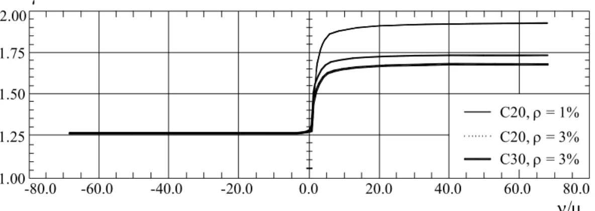
However, it should be referred that the variation of the global safety coefficient, described below, depends on the load eccentricity (the relation between the section’s acting bending moment and axial force). Figure 4 shows the variation of global safety coefficient, γ, with ν/µ relation, defined at section’s collapse (considering design values for the materials properties). The ν/µ is a non dimensionlised parameter that represents the reverse proportion of stress resultant eccentricity, at collapse, divided by section’s height, h, d Sd Sd e h h M N = ⋅ = µ ν (5) where NSd was considered positive for compression.
Figure 4 was obtained from the study of a symmetrically reinforced rectangular section, considering two different kinds of concrete (C20 and C30) and two amounts of reinforcement (ρ = 1% and ρ = 3%). As shown, the relation ν/µ presents a strong variation at the region of moderate compression axial force (axial compression levels lower than 0.5, shadowed area in figure 3). This strong variation of the
safety coefficient is due to the progressive transition from collapse conditioned by steel to collapse conditioned by concrete. From this figure we can conclude that, for sections submitted to tension, the
global coefficient is lower than 1.30. In pure tension, this coefficient is given by the relationship
between fsym and fsyd (fsym/fsyd = 1.265). For sections that are subject to compression stresses, the
concrete capacity will progressively increase until it reaches axial stress resultant levels close to 0.4,
and then stabilising. In this region, the value expressed by the coefficient will depend strongly on the section’s reinforcement amount (for the same type of concrete, C20, the values are 1.93, for ρ = 1%,
and 1.74 for ρ = 3%) and weakly on the concrete maximum resistance (for the same amount of reinforcement, ρ = 3%, it varies from 1.74, for C20, to 1.68 to C30).
1.25 -80.0 1.00 -60.0 -40.0 -20.0 0.0 1.50 1.75
γ
2.00 20.0 40.0 60.0 80.0ν/µ
C30, ρ = 3% C20, ρ = 3% C20, ρ = 1%Fig. 4 - Global safety coefficient variation with coefficient ν/µ, for a rectangular cross section with symmetric reinforcement.
Considering all factors listed above, it would be very difficult to define a global safety coefficient, γ, applicable to stress resultants calculated with the material’s medium resistant values to achieve a resistance similar to the one obtained from partial safety coefficients. Therefore, this does not appear to be the most convenient way to perform physically non-linear analyses.
4.1.2 Problems in the application to physical and geometrical non-linear analysis
The use of this safety format in physical and geometrical non-linear analysis is, however, even more controversial, because the difficulties associated to the specification of the materials global safety coefficient do not depend on the non-totally parameterised loads alone. The application of this safety format to structures sensitive to second order effects raises several problems. In this type of structures, the calculation should be performed by means of a non-linear physic and geometrical analysis, due to the deformation’s impact on the elements stresses. The adoption of a safety format based on a global factor presupposes the performance of the analysis till collapse using medium values for the materials’ properties. Stress resultants are then affected by the safety coefficients in order to obtain the correspondent design values. As shown above, it is here the method’s shortcomings arise.
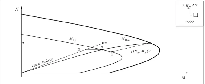
Let’s consider one cantilever, of rectangular cross-section, acted by a totally parameterised load, Λ(N, H) at its free end. The variation of stress resultants at the restrained end, obtained by means of a non-linear analysis performed with medium values, is shown in figure 5, as well as the variation of elastic stress resultants. This enables us to distinguish the two components of the bending moments: the first order medium moment, M1,m, and the increment due to the structure’s deformation, M2,m. The envelopes of resistant stress resultants NRd-MRd, represented in figure 5, were obtained using the materials’ design values as well as the medium ones.
The figure shows that it is very difficult to choose a global factor, with which the results of a non-linear analysis can be transformed in design values. If the coefficient is applied simultaneously to both stress resultants, acting at a section at collapse (point B), the result does not correspond to the applied actions (point C). If the safety coefficient is applied to actions (but not to its effects), second order effects will not be correctly accounted for.
With respect to the results obtained in a non-linear analysis performed till collapse, with materials’ medium values (figure 5), some comments should be made. Using this method, the passage through a pair of stress-resultants identical to those adopted in the design of critical section (point A) cannot be settle as a collapse situation. Structural deformability wouldn’t be affected by any safety coefficient and there isn’t any relation between tension-extension diagrams associated to those design
γ (N , M ) ? N m m M Λ H ΛN Linear A nalysis M I,m M II,m A C D
Fig. 5 - Application of a global safety coefficient: analysis till collapse with medium values. hypotheses that justifies such a procedure. The stress resultant‘s increment, related to the elastic ones, obtained by the application of a global safety coefficient (difference between D and C in figure 5) could also be understood as an indirect way of 2nd order effects aggravation. However, not only it is not an accurate procedure, it also leads to 2nd order effects that are greater than those obtained through a physic and geometrically non-linear analysis performed with design constitutive relationships, on all columns’ sections (in this hypothesis the obtained result is somewhere between A and C, over de resistant envelope). It should also be referred that collapse will occur for higher loads than the design ones. Structural deformability being dependent on load level and influencing itself the introduced 2nd order effects, the application of a global safety coefficient to final results will always be questionable (it may lead to 2nd order effect’s overestimation). Finally, the problem is even more complex if one pretends to apply this safety format to hiperstatic structures, with stress redistribution capacity. In these structures, not only is the differentiation between 1st and 2nd order stress not possible, the stress resultant’s increment rate at the element’s sections varies during charge. This detail would lead, at collapse, to distinct safety coefficients for the most loaded sections.
Taking into account all reasons referred above, it is very difficult to accept in a non-linear analysis a safety format based on a global safety coefficient.
4.2 Partial coefficients
Another way of applying the safety format in a non-linear analysis of reinforced concrete structures is to adopt partial safety coefficients applied directly to the materials’ stress relationships.
It is important to notice that, although not explicitly specifying this methodology, MC90 [9] (§6.6.2.3) settles that structural deformations have to be calculated adopting for concrete the relationship shown in figure 1, defined by design values of fcd and Ecd obtained with a safety coefficient γc=1.20. However,
for ultimate stress resultant calculation at critical sections (local verification) a safety coefficient of γc=1.50 should be used.
The introduction of these concepts in a computer program is not easy or consensual, due to the relation between those two characteristics of structural behaviour: resistance and deformability. Nevertheless, the most important advantage of this format, when compared with global safety coefficients, is that it does not allow exceeding resistant design stress resultants, in any section, during the analysis.
More recently, in January, the last Draft of EC2 [10] finally proposes the adoption of design relationships for concrete, when using non-linear analysis, as proposed by the author since 1995 [13]. 4.2.1 Influence on collapse load parameter
The usual design process for reinforced concrete structures presupposes the elastic stress calculation, with or without redistribution (calculation performed with actions increased by safety coefficients), followed by the calculation of the amounts of reinforced steel needed in all the elements’ cross sections. For that propose, design material’s relationships are usually adopted (parabolic-rectangular relation or similar, for concrete, and elastic-plastic relation, with or without hardening, for steel). Let us assume that the strictly necessary amounts of reinforcement, required for ultimate limit state verification, are placed at the most loaded sections. The sections’ resistant capacity being
defined, if a physically non-linear analysis is performed using materials’ design stress relationships, collapse will be achieved for a load near the one considered at design (in some cases precocious collapse can occur due to a lack of rotation or redistribution capability — usually associated to high compression levels, low reinforcement amounts or simultaneously existence of elements with significant different stiffness).
This feature (achieving collapse load parameters similar to design in physical non-linear analysis) is, without any doubt, one of the major advantages of this methodology. After knowing the collapse load given by that analysis, it is possible to estimate and quantify the importance of geometrically non-linear effects from the load parameter reduction, ∆Λ, obtained in a totally non-non-linear analysis (physical and geometrical), given by the relation
NLF NLFG 0 . 1 Λ Λ ∆Λ = − (6)
where ΛNLFG is the collapse load parameter, through a physical and geometrical non-linear analysis and ΛNLF is the collapse load parameter through a physical non-linear analysis (which will be, in general, around 1.50 if γg=γq=1.50).
4.2.2 Influence on displacements
The adoption of design values for the constitutive relationships of the materials properties, for one and the same acting load level, leads to bigger deformations than those obtained with medium values, in non-linear analysis. Consequently, the resulting displacements can be overestimated. This constitutes one of its major shortcomings. As we have already referred, the incremental stiffness matrix depends on the tangent modulus of elasticity associated to all concrete and steel layers in which the sections are discretized. While the steel elasticity modulus is considered constant till yielding, the concrete elasticity modulus associated to a certain deformation level depends on its initial value and mostly on the concrete’s maximum compression tension. For this reason, the adoption of safety coefficients that decrease the material properties will directly influence the structural deformability, leading to bigger displacements.
It should however be referred that the over-measurement of the structural deformability will influence the results of 2nd order sensitive structures analysis. The over-measurement of structural displacements will also be associated to a structural design whose 2nd order effects are more significant than the actual ones and, therefore, to a safety design. It is also important to notice that the safety format also has to be applied to structural displacements whenever they affect the stress resultants. In our opinion, the displacement calculation using medium values for the material’s properties, as proposed by EC2 [10], will only be acceptable if their impact on the stress resultants is correctly estimated. This can be done a posteriori through some coefficients although it is difficult to
perform in a non-linear analysis, as we already have referred.
Taking into account the pros and cons of the presented methodologies, we consider it preferable to affect the materials’ constitutive relationships by using safety coefficients. This method presents the advantage of applying, in a direct way, the safety philosophy simultaneously to deformations and to internal stress resultants (the influence of deformability in structural stresses being automatically processed). Besides, it is assured that the design stresses are not exceeded at any section.
One way of achieving lower structural displacements is to consider the material’s constitutive relationships in non-conditioning regions affected by lower safety coefficients (the columns’ intermediate zones and the beams’ regions between end nodes and mid span in reinforced concrete portal frames can be considered non-conditioning regions). Another way of achieving lower displacements is to consider tension-stiffening effects (with its correspondent increment of structural stiffness). However, tension-stiffening effects are significant only in cases of low rates of reinforcement and, where second order effects are important, when the ultimate state limit occurs before reinforcement yielding (MC90 [9]).
5 NEW PROPOSAL FOR DESIGNING WITH NON-LINEAR ANALYSES
Nowadays, the use of non-linear analysis in design is generalized. That is why almost all codes, including EC2 [10], enable and specify its use for design of concrete structures. Unfortunately, although the principles for non-linear analysis are set, the codes do not give any orientations for designing with this powerful tool. When 2nd order effects are important, the designers have to decide how to include them in the design process and how to achieve a safety solution. Once decided to use a non-linear program it is difficult to accept to perform the evaluation of those effects by simplified
methods. Several studies developed by the author and others [1], [13], [14] enabled to conclude that a consistent and simple way to design with non-linear programs and taking into account 2nd order effects can be done by executing the following steps:
1. determination of elements’ elastic stresses (linear analysis);
2. section’s design (quantification of reinforcement amounts needed for elastic stresses);
3. execution of a physical and geometrically non-linear analysis, till collapse, with design constitutive relationships for steel and concrete and determination of the load parameter at collapse, ΛNLFG;
4. redesign of all critical sections for the internal stresses obtained in step 3, multiplied by
1.50/ ΛNLFG (assuming that the design process’ objective was to achieve a load parameter of
1.50);
5. execution of a new non-linear analysis with the obtained reinforcement.
The process described above should be repeated (steps 3 to 5) till achieving an acceptable difference between the load parameter objective (usually 1.50) and the non-linear analysis load
parameter, ΛNLFG (lower than 5%, for example). The method converges in two or three iterations,
gives excellent results (the 2nd order effects will automatically be taken into account) and constitutes a coherent and complete guide for concrete structures’ designers.
6 CONCLUSIONS
In this paper, different safety formats were analysed and their most important variables, as well as the uncertainties and difficulties associated to structural reliability.
Of all available formats, those based on safety coefficients (level 1 formats) are well adapted to reinforced concrete structures. That is why they are usually used in non-linear analysis. The application of safety coefficients to actions and to the materials’ relationships was discussed. With regard to the coefficients applied to the materials relationships, global and partial methodologies were analysed and reviewed. The major difficulties connected to their application were analysed and the conclusion was drawn that it is advisable to adopt partial safety coefficients to the materials relationships.
Finally, a simple method using non-linear analyses for reinforced concrete structures’ design, with important 2nd order effects, was presented. This method constitutes a complete and coherent design tool for project.
7 ACKNOWLEDGE
The author acknowledges the Instituto da Construção from the Civil Engineering Department of Instituto Superior Técnico (Technical University of Lisbon) the technical support and equipment that enabled the execution of this work.
REFERENCES
[1] Vinagre, J. : Avaliação dos efeitos de 2ª ordem em edifícios de betão armado. PhD Thesys, Instituto Superior Técnico, March, 1997 (in Portuguese).
[2] Thoft-Christensen, P. : Fundamentals of structural reliability. ISPRA Courses, SR/89/1, 17 pp., Lisboa, November, 1989.
[3] Ferry-Borges, J. ; Castanheta, M.: Structural safety. 3rd Edition, LNEC, Lisboa, November, 1984.
[4] Eibl, J. : Safety considerations for non-linear analysis. Structural Concrete, IABSE Colloquium, pp.337-342, Stuttgart, 1991.
[5] Henriques, A. A. R. : Aplicação de novos conceitos de segurança no dimensionamento do betão estrutural. PhD Thesys, FEUP, Porto, 1998 (in Portuguese).
[6] Veneziano, D. : Basic principles and methods of structural safety. CEB, nº 112, Paris, 1976. [7] Thoft-Christensen, P. : Reliability of structural systems. ISPRA Courses, SR/89/3, 17 pp., Lisboa,
November, 1989.
[8] Regulamento de estruturas de betão armado e pré-esforçado. INCM, Lisboa, 1985 (Portuguese Code).
[9] CEB-FIP Model Code 1990 Design Code. Comité Euro-International du Béton, 1993.
[10] Eurocode 2 : Design of concrete structures. Part 2: Concrete Bridges. 2nd Draft, Bruxelas,
[11] ACI Committee 318 : Building code requirements for reinforced concrete (ACI 318-89) and Commentary (ACI 318 RM-89). ACI, Detroit, 1990.
[12] König, G.; Novák B. : Development on EC2, Part 2 for concrete bridges. Darmstadt Concrete, vol. 7, pp. 121-128, 1992.
[13] Vinagre, J.; Camara, J. : Simplified methods for 2nd order effects evaluation in reinforced concrete columns. International Conference on Promotion and Enhancement of Computational Methods in Engineering and Science, EPMESC VII, Macau, August, 1999.
[14] Castro, P. M. R. P. : Modelos para análise da encurvadura em pórticos de betão armado. PhD Thesys, FEUP, October, 1998, (in Portuguese).