Journal of Applied Research and Technology 259
A Blind Data Hiding Technique with Error Correction Abilities and a
High Embedding Payload
H. Y. Liang1, C. H. Cheng*2, C. Y. Yang3, K. F. Zhang4 1,4 Department of Information and Communication Engineering Chaoyang University of Technology
Taichung, 4139, Taiwan 2
Department of Electrical Engineering National Formosa University
Yunlin, 632, Taiwan * [email protected]
3 Department of Computer Science Taipei Municipal University of Education Taipei, 10042, Taiwan
ABSTRACT
Least significant bit (LSB) embedding is a simple steganographic technique used in the spatial domain that involves replacing the LSB of each pixel in the cover work with the information bits being hidden to achieve information secrecy. However, considering the current prevalence of information theft and sabotage, the stego image produced using LSB embedding cannot prevent malicious illegal acts. Therefore, this study proposes a blind data hiding technique that combines block-coded modulation (BCM) codes with LSB embedding. The proposed method not only provides error correction capabilities to prevent errors during the extraction process, but also has a superior embedding payload. The peak signal noise ratio (PSNR) exceeds 40 dB by using our proposed method. Regarding the simulation results, the proposed method provides a superior PSNR compared to LSB embedding and a higher embedding payload than that offered by other steganographic techniques with error correction capabilities.
Keywords: Least significant bit embedding, data hiding, block-coded modulation codes, Reed-Muller codes.
1. Introduction
Watermarking [1, 2, 3, 4, 5] and steganography [6, 7, 8, 9] are the two main information hiding techni-ques that are used to protect intellectual property by embedding copyright information into digital media such as images, music, and videos. To explain watermarking, consider invisible watermar-king as an example; invisible watermarwatermar-king is employed to embed visually imperceptible data or ciphers into cover work. Steganography involves embedding information (cipher) in cover work thr-ough undetectable changes. A major characteristic of blind data hiding watermarking techniques is that the extraction processing can extract the hidd-en information without cover work. The extraction process that does require cover work is called info-rmed data hiding. To evaluate the efficiency of ste-ganographic techniques, Chang [10] recommende-d two criteria to evaluate steganographic techniqu-es, namely, embedding efficiency and embedding payload. Embedding efficiency describes the visual
quality of the stego image, and the embedding payload refers to the size of the embedded cipher. Generally, embedding efficiency uses a peak sign-al noise ratio (PSNR) to evsign-aluate the visusign-al qusign-ality. When the PSNR value exceeds 30 dB, the human eye cannot detect visual differences between embedded and nonembedded images. Thus, the optimal information hiding technique should have both a high embedding payload and high embeddi-ng efficiency. Consideriembeddi-ng the current prevalence of information theft and sabotage, producing stego images within acceptable bounds of the two criteria while effectively preventing malicious illegal acts has become a popular research objective.
A Blind Data Hiding Technique with Error Correction Abilities and a High Embedding Payload, H. Y. Liang et al. / 259‐271
Vol. 11, April 2013 260
pixels of the cover work, respectively. The simulat-ion results indicated that the proposed method provided superior PSNR compared to LSB embed-ding. Briefly, the proposed method first divided 7 secret bits into 3 bits and 4 bits, which were then used to locate the selected codeword in each row and column of the 8 16 standard array. Next, each selected codeword was embedded into every 7 pixels of the cover work using LSB embedding until all secret bits were embedded. The extraction process involves extracting the LSB of every 7 pix-els of the stego image and locating the codeword in every row and column of the 8 16 standard ar-ray. Every 7 secret bits extracted can be identified by converting the row number and column number into 3 bits and 4 bits. The method proposed by Chang requires greater memory because the prop-osed method employs a lookup table for embeddi-ng and extractiembeddi-ng secret bits. Moreover, the error correction capability of this method can correct only single-bit errors. Therefore, how to further im-prove the error correction capability and embedd-ing payload of the method proposed by Chang is a popular research topic.
This study combines block coded modulation (BCM) codes with LSB embedding to improve both the error correction capability and embedding payload of Chang’s proposed method. To further improve the PSNR of the proposed method, this study employs modulus functions [11] to increase the differences between the cover work and stego image before embedding BCM codewords into the cover work. The simulation results show that the method proposed in this study possess superior error correction and LSB embedding capabilities than that of the method proposed by Chang when the stego image is corrupted by salt-and-pepper noise. Furthermore, our proposed method also off-ers a higher embedding payload than that provided by Chang’s proposed method.
2. Literature Review
In this section, we first describe the encoding and decoding architecture of BCM codes and Reed-Muller codes. Then, we explicate the embedding and extraction processes of the following three techniques: LSB embedding, Chang’s proposed method [10], and the modulus function.
2.1 BCM Codes
BCM [12] is a coding scheme that combines both modulation and channel coding and is based on the Euclidean distance between symbols. For convenience, we describe how to construct a 4-QAM BCM code based on a 4-4-QAM signal constellation with set partitioning. First, symbols within the signal constellations are recursively divided into numerous subsets, where the Euclidean distance between the neighboring symbols of each subset are gradually increased. A 4-QAM BCM code is composed of two component codes C1 and C2, which are binary block codes with length N. The minimum Hamming distance is di, where 1 i 2. The two component codes are used to construct a
2 N codeword array by inserting the codeword
i
c of the ith component code Ci into the ith row of a 2N codeword array. This is represented in the following mathematical expression:
1,0 1,1 1, 1
1 1
2,0 2,1 2, 1
2 2
N N
c c c
C
c c c
C c c
Next, a 4-QAM BCM codeword with length N is created by modulating each column of the codeword array into a 4-QAM symbol. Figure 1 shows a 4-QAM signal constellation, where the bit indicators are arranged by set partitioning and the ratio between the squared Euclidean distances of the two subsets is 1:2. A 4-QAM BCM codeword
X X0, 1,,XN 1
X can be expressed using the
following mathematical equation:
1, 22, 4
1
, 0 1,
2
k k j
c c
k
X j e k N
where j 1. This mathematical expression shows that the 4-QAM BCM codeword X is composed of two binary component codewords
, 1,2
i C ii
c .
2.2 Reed-Muller codes
Journal of Applied Research and Technology 261 Let m and r be the two positive integers and
0 r m. A rth-order binary Reed-Muller code with a code length of N 2m, which is a
2 ,
0 , 2 r
m m r
i
m
N k d
i
linear block code, can be expressed as RM(r,m). Assuming 1 i m, let xi be a vector of length
2m
that exists in the binary Galois field with the following characteristics:
1 1
1 2 1 2
2 2
(0, ,0,1, ,1,0, ,0, ,1, ,1)
i i
i i
i x
where (
1
2 0, ,0
i
) and (
1
2 1, ,1
i
) are 2i1-tuples with all zeroes and all ones as the content, respectively [12]. For example, if m = 3, the three vectors existing in the binary Galois field of length 8 can be expressed as
1 2
3
(0,1,0,1,0,1,0,1), (0,0,1,1,0,0,1,1), (0,0,0,0,1,1,1,1).
x x x
2.2.1 Encoding Reed-Muller codes
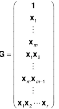
For an rth-order binary Reed-Muller code with a code length of 2m, the generator matrix G of
RM(r,m) can be expressed as follows:
1
1 2
1
1 2
m
m m
r 1 x
x
G x x
x x
x x x
,
where 1 is a vector of length 2m
and the content is all ones. In other words, an rth-order binary Reed-Muller codeword is obtained through a linear combination of the vectors
{1,x1,...,xm,x x1 2,...,x xm m1,...,x x1 2xr}.
For example, m = 3 and r = 2, the generator matrix of RM (2,3) is a matrix sized k n 7 8, as shown below.
1 2
2
A Blind Data Hiding Technique with Error Correction Abilities and a High Embedding Payload, H. Y. Liang et al. / 259‐271
Vol. 11, April 2013 262 1 2 3 1 2 1 3 2 3 1 1,1,1,1,1,1,1,1 0,1,0,1,0,1,0,1 0,0,1,1,0,0,1,1 0,0,0,0,1,1,1,1 0,0,0,1,0,0,0,1 0,0,0,0,0,1,0,1 0,0,0,0,0,0,1,1 x x G x x x x x x x
Assuming the input message is u(1,0,1,0,0,0,0), the output codeword c is expressed as follows:
1,1,1,1,1,1,1,1 0,1,0,1,0,1,0,1 0,0,1,1,0,0,1,1 (1,0,1,0,0,0,0) 0,0,0,0,1,1,1,1 0,0,0,1,0,0,0,1 0,0,0,0,0,1,0,1 0,0,0,0,0,0,1,1 0,0,1,1,0,0,1,1 c uG2.2.2 Decoding Reed-Muller codes
The Reed decoding algorithm is a type of decoding algorithm for RM(r,m) [12]. Using RM(2,3) as an example, assuming the input message is
(u u u u u0, ,1 2, 3, 12,u13,u23)
u and the received
codeword is r( , , , , , , , )r r r r r r r r1 2 3 4 5 6 7 8 , the decoded value '
12
u of input message bit u12 is determined by the results of the two decision equations below.
(1)
12 5 6 7 8
(2)
12 1 2 3 4
u r r r r
u r r r r
If both (1) 12
u and (2) 12
u are 1, then the input message bit u12 is decoded as '
12
u =1. Conversely, if both (1)
12
u and (2) 12
u are zeroes, then the decoded input message bit '
12
u is zero. Calculation of the above equations is known as binary addition; that is, 1+1=0, 1+0=1, 0+1=1, and 0+0=0. The corresponding positions in the received codeword of two decision equations are based on the non-zero positions in the two vectors {x3,1x3}. The
decision equations for decoding input messages 13
u and u23 are determined by summing the non-zero positions from {x2,1x2} and {x1,1x1} of the received codeword for decision equations, as shown below. (1)
13 3 4 7 8
(2)
13 1 2 5 6
(1)
23 2 4 6 8
(2)
23 1 3 5 7
u r r r r
u r r r r
u r r r r
u r r r r
The first stage correction involves adjusting the received codeword according to the decoded
' ' ' 12 13 23
(u ,u ,u ). After this adjustment, the received codeword of the first stage correction is defined as
'
12 1 2 13 1 3 23 2 3
' ' '
u u u
r r x x x x x x
. The input m-essage ( ,u u u1 2, 3) is then decoded from the con-tent of r', where the input message bit
1
u may be decoded to determine the decoded value '
1 u using the results of the following four decision equations.
(1) ' '
1 7 8
(2) ' '
1 5 6
(3) ' '
1 3 4
( 4) ' '
1 1 2
u r r
u r r
u r r
u r r
If most of the results of these four decision equations are zeroes, the input message u1 is decoded as '
1
u = 0. Conversely, if most of the resul-ts of these four decision equations is 1, then the input message u1 is decoded as '
1
u = 1. The four decision equations were decoded by summing the corresponding non-zero positions of the codewor-ds received from the four vectors
{x x2 3,(1x x x2) 3, 2(1x3),(1x2)(1x3)}.
Therefore, the decision equations for decoding the input messages u2 and u3 are based respectively on the sum of the corresponding non-zero positio-ns from the received codewords in
Journal of Applied Research and Technology 263 and
{x x1 2,(1x x x1) 2, 1(1x2),(1x1)(1x2)}.
The decoded ' ' ' 1 2 3
( ,u u u, ) are then used in the seco-nd stage correction. The received codeword of the second stage correction is defined as
'' '
1 1 2 2 3 3
' ' '
u u u
r r x x x ,
which is used to determine the decoded value of the input message bit u0. If the majority of the con-tent value for r''is 0, then the input message bit
0 u is decoded as '
0
u = 0. Conversely, u0 is decoded as '
0
u = 1 if the majority of the content value for r''is 1. Finally, the input message decoded using the Reed decoding algorithm is
' ' ' ' ' ' ' '
0 1 2 3 12 13 23 (u u u u u, , , , ,u ,u )
u .
2.3Chang's proposed method [10]
For a cover work sized MW , the method proposed by Chang employs the Hamming code [7,4] to hide information. The amount of data that can be hidden is (MW) 7, where y denotes the smallest positive integer that is less than y. Chang’s proposed method hides information using the Hamming code [7,4], with a standard array of 8 16 . Seven bits are read from the data to be hidden and then divided into 3 bits and 4 bits. The 3 bits are used to express which of the 8 coset leaders should be selected, and the 4 bits denote which of the 16 codewords should be chosen. Chang’s proposed method adds the selected coset leader and codeword using the vector from additions as the information to embed into the cover work. The method to embed information involves obtaining 7 pixels from the cover work and then replacing the LSB content of the 7 pixels with the selected processed information in sequence.
Data is extracted from the receiver by reading the LSB content of the 7 pixels in the sequence that data are embedded into the cover work. The 7 bits obtained using this method are multiplied by the
parity check matrix H of the Hamming code [7,4] to obtain the 3 bits syndrome. The coset leader corresponding to the syndrome is added to the extracted 7 bits to obtain the codeword, and the 4 bits corresponding to the codeword are revealed using the standard array, thereby retrieving the embedded 7 bits of hidden data. Because Chang’s proposed method requires the standard array to be built beforehand, extra memory is required in both the transmitter and the receiver to store the 128 vectors required for embedding and decoding. If the code length N for the Hamming code is extended, the vectors requiring storage increase to the nth power of 2, that is, 2n, which increases the overall
costs. Thus, we propose a steganographic technique based on BCM architecture and select Reed-Muller codes as component codes. This is primarily because the Reed decoding algorithm can be decoded through easy calculations and does not require substantial memory to build the standard array, thereby effectively improving the high storage requirements of Chang’s proposed method.
2.4 Modulus function
Thien and Lin [11] proposed a steganographic technique to improve the visual quality of the stego image using modulus functions. The expression of modulus function is defined as c = a mod b, where a is the dividend, b is the divisor, and c is the reminder. For example, 3 mod 2 equals 1, that is, the division of 3 by 2 leaves a remainder of 1. Let x be a pixel used to hide data in the cover work, z be the hidden information, and y equal log2z. First, the embedding process of modulus function is em-ployed to compute the following equation:
w=z- (x mod y).
The result w is applied to determine the minimum variance e using the following equations:
1 1
, if
2 2
1 , if 1
2
1
, if ( 1)
2
y y
w w
y
e w y y w
y
A Blind Data Hiding Technique with Error Correction Abilities and a High Embedding Payload, H. Y. Liang et al. / 259‐271
Vol. 11, April 2013 264
where s represents the smallest integer closest to s, and v represents the largest integer closest to v. Finally, the modified pixel 'x , which replaces x in the cover work, is obtained by calculating
'
x x e. The modulus function extraction proce-ss involves computing zx' mod yto extract the information hidden in the stego image. Although the modulus function offers superior visual quality, it has no error correction capabilities to prevent errors in the extraction process. Therefore, this study uses BCM codes to improve the error correc-tion capabilities of the modulus funccorrec-tion.
3 The proposed method
This study proposes a steganographic technique that offers both error correction capabilities and superior visual quality. The proposed method, which can be used in blind data hiding watermar-king systems, integrates BCM codes to improve the error correction capabilities of LSB embedding. This study also employs a modulus function to improve the PSNR of the proposed method because using more LSBs to embed hidden information reduces the PSNR. Because every bit of a binary sequence converted by a pixel can be considered a subset of the signal constellation, this study employs various order Reed-Muller codes as the component codes of BCM codes to protect the LSB of each pixel when errors occur during the extraction process. Because the impact on visual quality is lower when information in hidden the first LSB compared to the other LSB, the block codes used to hide information in the first LSB must have equal or superior error correction capabilities to maintain both a high error correction capability and embedding payload. Therefore, the block code encoding length of the first LSB must be less than that of the second LSB. For example, if the block code chosen for the first LSB is a RM(2,4) with a code length of 16 and the ability to correct 1-bit errors, then the block code chosen for the second LSB must use a block code longer than 16 bits and correct 1 or more bits, such as RM(2,5) with a code length of 32 and the ability to correct 3-bit errors. The data encoding and extraction processes of the method proposed in this study are explained below.
In this study, a grayscale image sized at MW was used as the cover work, and Reed-Muller codes were used as the component codes of BCM codes. 3.1 Data embedding procedures
Assume n is the number of LSBs used for hiding information. Let the block code used for hiding information in the ith LSB be RM r m( ,i i), where
( ,i i) RM r m is a
2 , ,
' 0 ' 2 i
i r i i
m i m r
i i i i
m
n k d
i
linear block code and i 1,2, , .n The linear block code selected as the component code must satisfy the conditions of nj1nj and dj1dj,
1,2,,6
j . First, a grayscale image sized at
M W was adopted as the cover work, and the block divisions required for hiding information in the ith LSB were calculated. That is, the MW pixels pf,1 f M W of the grayscale image
were divided into 2mi
M W
blocks ( ) ',
i i
b 1i'
2mi
M W
and i 1,2,,n, where each block contains 2mi pixels. The proposed method is used to determine the size of the information hidden as S and sized at
1M
( )
2 i
n
i m
i
W
k bits, where n is the number of LSBs used to hide the information. Then, the ki bits obtained from the data being hidden and marked as
,1, ,2,, ,
i
i ui ui ui k
u are
converted into Reed-Muller codewords ci after the Reed-Muller encoding process is performed. Specifically, the codeword ci is generated from
i i i
c u G, where Gi is the generator matrix for ( ,i i)
Journal of Applied Research and Technology 265 proposed method sequentially embeds the content
of codeword ci with the length of 2mi into the ith LSB of the divided blocks. This method can be expressed as the ith LSB ( (i) ( )
i i
v i
s v
l b )= (,i) i
v i s
c . (i) i
v s l is the binary sequence converted from the sith pixel in block vi, ( )
vi
i
b is the vith block divided during the ith LSB embedding, and (,i)
i
v i s
c is the sith element from the codeword that is hidden in the vith block in the ith LSB, where 1 2mi
i
s and
1 2 i i m M W
v . Each modified pixel p't of the
1
v th block after the n-bit LSB embedding is used as the input value of the modulus function, where
1,2,2m1
t and n is the number of LSBs used for hiding information. We first employed modulus operation to calculate the following equation:
' ( mod 2 ), i
t t t
w p p
where pt is the original tth pixel of the v1th block in the cover work and t 1,2,,2m1. Then, the
resulting value wt was used to determine the minimum variance et through the following equations:
2 1 2 1
, if
2 2
2 1
2 , if 2 1 ,
2
2 1
2 , if (2 1)
2
i i
t t
i
i i
t t t
i
i i
t t
w w
e w w
w w
(1) where s represents the smallest integer closest to s, v represents the largest integer closest to v, i = 1,2,..., n, and t 1,2,,2m1. After calculating
the modulus function, the resulting pixel *
t
p is obtained using the following decision equations.
* * * * * * *
( ), if 0 255
( 2 ), if 255
( 2 ), if 0
t t t t
i
t t t t t
i
t t t t
p e p e
p p e p e
p e p e
,
(2) where t1,2,,2m1. The embedding process is
explained below.
Procedure: Data embedding
Input: Hidden data S, n LSBs embedded into a pixel, and a grayscale image MWin size, where the grayscale image is used as the cover work.
( ,i i)
RM r m is used as the block codes for hiding information in the ith LSB, where nj1nj and
1
j j
d d , j 1,2,,6and i=1,2,...,n.
Output: A stego image I' MW in size.
Step 1: Define the sequence of the MW pixels in the grayscale image I, where
,1 f
p f M W , and divide the blocks according to the following procedure: Blocks required to hide information in the
ith LSB: Divide the MW pixels
,1 f
p f M W in the grayscale image into
2mi
M W
blocks ( ), i
i v
b 1vi
2mi
M W
, where each block contains 2mi pixels.
Step 2: Read the next i
v
k data bits from the payload S and mark as
1,1, 1,2, , 1,
i vi
v u u uk
s .
Step 3: Generate the codeword i
v
c from
i i
v v i
c s G ,
A Blind Data Hiding Technique with Error Correction Abilities and a High Embedding Payload, H. Y. Liang et al. / 259‐271
Vol. 11, April 2013 266
Step 4: Replace the ith LSBs content of the binary sequence that corresponds with the 2mipixels in block ( )
i
i v
b with content (,i) i
v i s
c from the codeword i
v
c . This can also be expressed as the ith LSB (
(i) ( )
i i
v i
s v
l b )
= (,i) i
v i s
c , where 1 2mi
i
s and 1vi
2mi
M W .
Step 5: Compute the resulting value wt according
to ' ( mod 2 )i
t t t
w p p , where pt is the original tth pixel of the v1th block in the cover work and
1,2,2m1
t . Use the resulting value wt to determine the minimum variance et according to (1). Finally, the resulting pixel *
t
p t1,2,2m1 can
be obtained using (2).
Step 6: Replace the tth pixel pt of the v1th block with the resulting pixel *
t
p , where t1,2,,2m1 and
1
1 1
2m
M W
v .
Step 7: Repeat Steps 2 to 6 until all payload S is embedded.
3.2 Data extraction procedures
Assuming the receiver is aware that the stego image is a grayscale image and the parameters of the Reed-Muller codes are ri and mi, when the receiver receives the stego image, all the stego image pixels use modulo 2i operation.
Additionally, the stego image after modulus operation is divided into
2mi
M W
blocks for extracting information from the ith LSB. Specifically, each block used to extract information from the ith LSB contains 2mi pixels
' ' ( ) , , t v t received
p t'1,2,,2mi, and
'
1
2mi
t
M W
v .
Pixels from each block containing ith LSB hidden information are converted into a binary sequence
' ' ' ' ' ' ' ' '
'
( ) ( ) ( ) ( ) ( ) ( ) ( ) ( ) ( ) 1 ,2 ,3 , 4 ,5 ,6 ,7 ,8
t t t t t t t t t
v v v v v v v v v
t l l l l l l l l
l , where
t' 1,2, ,2mi and
'
1
2mi
t
M W
v .The ith LSB f-rom the 2mipixels in the
i
v th steganographic blocks is extracted, where
1
2 i
i m
M W
v . The
extra-cted LSBs are combined into the binary sequences andexpressed as
( ) ( ) ( ) ( )
1 2 2
th LSB( ), th LSB( ), , th LSB( )
i i i i
mi
v v v v
i i i i
d l l l .
Finally, the binary sequences (vi)
i
d from each block are decoded with a rith order Reed decoding algorithm until all the payload S is extracted. The data extraction process can be consolidated into the following procedures:
Procedure: Data extraction
Input: A stego image I' MWin size with n LSBs embedded in each pixel, where the codewords are generated by RM r m( ,i i) and i = 1,2,..., n.
Output: Original payload S Step 1: First, all M N pixels
'
, ,
f received
p 1 f M W ,
in the stego image I' employ modulo 2n operation.
After modulus operation, divide the MWpixels
*
, , 1 ,
f received
p f M W into the
2mi
M W
information hiding blocks of the ith LSB, where each of the ith LSB blocks contain 2mi
pixels
' '
( )
, , t' 1,2, ,2
t i v m t received p and ' 1
2mi
t
M W
Journal of Applied Research and Technology 267
Step 2: Read each pixel in the subsequent ith LSB information hiding blocks and convert them into the binary sequences
' ' ' ' ' ' ' ' '
'
( ) ( ) ( ) ( ) ( ) ( ) ( ) ( ) ( ) 1 ,2 ,3 ,4 ,5 ,6 ,7 ,8
t t t t t t t t t
v v v v v v v v v
t l l l l l l l l
l ,
where t'1,2,,2mi and
'
1
2mi
t
M W
v .
Step 3: Extract the ith LSB from 2mi binary seque-nces '
'
( ) , t
v t
l
t' 1,2, ,2mi and
'
1
2mi
t
M W
v .
Assemble the extracted LSBs into binary sequenc-es exprsequenc-essed as
( ) ( ) ( )
1 2
th LSB( ), , th LSB( )
i i i
mi
v v v
i i i
d l l .
Step 4: Decode the extracted codewords (vi)
i
d into
i
s , using the rith order Reed decoding algorithm.
Step 5: Repeat Steps 2 to 4 until all payload S is extracted.
4. Experimental results
In this study, we conducted simulations using 8 grayscale images with 256 256 pixels, as shown
in Fig. 2. We assessed the degree of visual differences between the cover work and the stego image with the embedded information using the PSNRs. PSNR is defined as
2
10 255
PSNR=10log ,
MSE
where
2 1 1
'
, ,
0 0 1
MSE
M W
i j i j
i j
I I
M W , I is the origi-nal grayscale image, and I'is the stego image. Generally, when the PSNR exceeds 30 dB,
visually distinguishing the differences between the stego image and the cover work is extremely
difficult. To compare the payload size that can be embedded using various information hiding techniques, we assessed various embedding payloads P (calculated using the unit of bits-per-pixel, bpp), which can be defined as
,
S P
M W
where S refers to the size of the payload S. The larger the P value, the more data can be hidden in the stego image. Generally, PSNR declines with increases in the embedding payload.
Achieving a high embedding payload without being visually distinguishable by the human eye and simultaneously preventing errors is currently a popular topic of steganography research. The exp-erimental results indicate that the method propose-d in this stupropose-dy hipropose-des anpropose-d protects propose-data in the first a- nd second LSB of each pixel in the cover work. To further analyze the error correction capabilities of LSB embedding, the method proposed by Chang, and the method proposed in this paper, we compared situations where stego images are disr- upted by salt-and-pepper noise [13]. The value of each noisy pixel in the salt-and-pepper noise ranged between 0 and 255 and the image size was
256 256. The position where the stego image
was disrupted by noise was randomly distributed. We used the error correction rate, which is expressed below, to evaluate the error correction capabilities of each technique.
c. e
b C
b
In this equation, bcis the number of correct bits and beis the number of error bits after data extraction.
A Blind Data Hiding Technique with Error Correction Abilities and a High Embedding Payload, H. Y. Liang et al. / 259‐271
Vol. 11, April 2013 268
in the second LSB, the 256 256 image was
divided into 2,048 blocks with lengths of 16. In Fig. 1, the payload size of each stego image is 98,304
bit and
98,304 1.5 256 256 S
P
M W . The method
proposed in this study guarantees PSNR values above 40 dB. Figure 4 shows the baboon image converted into a stego image using LSB embedding, Chang’s proposed method, and the method proposed in this study. The experimental parameters are identical to those employed in Fig. 3; that is, the block codes employed for the first LSB and second LSB embedding are RM(2,4) and RM(3,5), respectively. The steganographic data extraction was disrupted by the same salt-and-pepper noise.
Assuming that half the 256 256 pixels in the stego image are disrupted by salt-and-pepper noise, as shown in Fig. 4(a), regardless of
whether the PSNR of Chang’s proposed method is superior to that of the method proposed in this study and of 2-bits LSB embedding, the embedding payload of the method proposed in this study is higher than that of Chang’s proposed method. In Fig. 4(b), the error correction rate of the method proposed in this study is superior to that of the two other techniques. Table 1 shows a comparison of the PSNR, embedding payload, and error correction rates of the three steganographic techniques applied to 8 images. However, no error correction rate is displayed for LSB embedding in Table 1 because
LSB embedding does not possess error correction capabilities. The results in Table 1 show that the method proposed in this study provides a PSNR and embedding payload nearly equivalent to that of 2-bits LSB embedding while offering almost dou-ble the error correction rates provided by the other two techniques.
Journal of Applied Research and Technology 269 Figure 3. The visual quality and embedding payload of the stego images created
using the method proposed in this study.
A Blind Data Hiding Technique with Error Correction Abilities and a High Embedding Payload, H. Y. Liang et al. / 259‐271
Vol. 11, April 2013 270
5. Conclusion
This study proposed a blind data hiding method with error correction capabilities and high embedding payloads by combining LSB embedd-ing and BCM to produce stego images. Compared with Chang’s proposed method, although the PSNR of the method proposed in this study is less than optimal, this method does not require substantial memory to construct standard arrays for extracting data. Additionally, our proposed method offers significantly superior embedding payloads and error correction capabilities.
Acknowledgements
This work was supported in part by the National Science Council (NSC) of Republic of China under grant NSC 101-2221-E-324-026 and NSC 101-2221-E-150-059 .
References
[1] F. Hartung and M. Kutter, "Multimedia Watermark-ing Techniques," Proceedings of the IEEE, vol. 87, no. 7, pp. 1079-1107, 1999.
[2] G. C. Langelaar, et al., "Watermarking digital image and video data. A state-of-the-art overview," IEEE Signal Processing Magazine, vol. 17, no.5, pp. 20-46, 2000.
[3] S. C Nirmal and B. Parthasarathy, "An Innovative Fusion Technique for Secured Video Watermark-ing," International Journal of Engineering and Innovative Technology, vol. 2, no. 2, pp. 20-22, 2012.
[4] S. Anand, et al., "Digital Watermarking," Internati-onal Journal of Enginee-ring and Innovative Technology, vol. 2, no. 2, pp. 151-155, 2012.
[5] C. C. Ramos, et al., "A Blind Video Watermarking Scheme Robust To Frame Attacks Combined With MPEG2 Compression," Journal of Applied Research and Technology, vol.8, no. 3, pp. 323-339, 2010.
[6] H. C. Wu, et al., "Image steganographic scheme based on pixel-value differencing and LSB replacement methods," IEE Proceedings Vision, Image and Signal Proces-sing, vol. 152, no. 5, pp. 611-615, 2005.
[7] A. D. Ker, "Steganalysis of LSB matching in grayscale images," IEEE Signal Processing Letters, vol. 12, no.6, pp. 441-444, 2005.
[8] P. R. Rudramath and M. R. Madki, "Improved BPCS Steganography Based Novel Approach for Data Embedding," International Journal of Engine-ering and Innovative Technology, vol. 1, no.3, pp. 156-159, 2012.
[9] P. V Bodhak and B. L Gunjal, "Improved Protection In Video Steganography Using DCT & LSB," International Journal of Engineering and Innovativ-e Technology, vol. 1, no. 4, pp. 31-37, 2012.
Image Name
PSNR Embedding payload
(P)
Error correction rate (C)
(a) (b) (c) (a) (b) (c) (a) (b) (c)
Lena 44.1683 48.9787 46.3463 2 0.99997 1.5 - 1.526 3.0292 Baboon 44.1586 50.1165 46.3728 2 0.99997 1.5 - 1.526 3.0292 Barbara 44.1398 48.6595 46.3881 2 0.99997 1.5 - 1.526 3.0292 Boats 44.1584 48.1376 46.3607 2 0.99997 1.5 - 1.526 3.0292 Bridge 44.1371 51.1283 46.3593 2 0.99997 1.5 - 1.526 3.0292 Jet (F16) 44.1502 47.0562 46.3713 2 0.99997 1.5 - 1.526 3.0292
Goldhill 44.1483 50.8054 46.3642 2 0.99997 1.5 - 1.526 3.0292 Zelda 44.1732 49.7253 46.34 2 0.99997 1.5 - 1.526 3.0292 Table 1. Comparison of the three steganographic techniques according to their PSNR, embedding payload,
Journal of Applied Research and Technology 271 [10] C. C. Chang,et al., "A High Payload
Steganographic Scheme Based on (7, 4) Hamming Code for Digital Images," International Symposium on Electronic Commerce and Security, Guangzhou, China, 2008, pp. 16-21.
[11] C. C. Thien and J. C. Lin, "A Simple and High-hiding Capacity Method for Hiding Digit-by-digit Data in Images Based on Modulus Function," Pattern Recognition, vol. 36, no. 12, pp. 2875-2881, 2003.
[12] S. Lin and D. J. Costello, "Error Control Coding: Fundamentals and Applications", Englewood Cliffs, NJ: Prentice-Hall, 2004, pp. 1063-1074.
[13] G. Pok, J. Liu, and A. S. Nair, "Selective removal of impulse noise based on homogeneity level information," IEEE Transactions on Image Processing, vol. 12, no. 1, pp. 85-92, 2003.