3D simulation of orthodontic tooth movement
Norman Duque Penedo*, Carlos Nelson Elias**,
Maria Christina Thomé Pacheco***, Jayme Pereira de Gouvêa****
Objective: To develop and validate a three-dimensional (3D) numerical model of a
maxil-lary central incisor to simulate tooth movement using the Finite Element Method (FEM).
Methods: This model encompasses the tooth, alveolar bone and periodontal ligament. It
allows the simulation of different tooth movements and the establishment of centers of rotation and resistance. It limits the movement into the periodontal space, recording the direction, quantifying tooth displacement and initial stress in the periodontal ligament.
Results: By assessing tooth displacements and the areas that receive initial stress it is possible to determine the different types of tooth movement. Orthodontic forces make it possible to quantify stress magnitude in each tooth area, in the periodontal ligament and in the alveolar bone. Based on the axial stress along the periodontal ligament and the stress in the capillary blood vessel (capillary blood stress) it is theoretically possible to predict the areas where bone remodeling is likely to occur. Conclusions: The model was validated by determining the modulus of elasticity of the periodontal ligament in a man-ner consistent with experimental data in the literature. The methods used in building the model enabled the creation of a complete model for a dental arch, which allows a number of simulations involving orthodontic mechanics.
Abstract
Keywords: Finite elements. Periodontal ligament. Tooth movement. Orthodontic forces. Axial stress.
* PhD in Metallurgical Engineering, Fluminense Federal University (UFF), Volta Redonda, Rio de Janeiro State, Brazil. ** PhD in Materials Science, Military Institute of Engineering (IME). Professor of Biomaterials, IME, Rio de Janeiro, Brazil.
*** PhD in Orthodontics, Federal University of Rio de Janeiro (UFRJ). Professor of Orthodontics, Federal University of Espírito Santo, Vitória, Espírito Santo State. **** PhD in Mechanical Engineering, PUC-RJ. Professor of Engineering, Fluminense Federal University, Volta Redonda, Rio de Janeiro State, Brazil.
IntROduCtIOn
The finite element method (FEM) enables the investigation of biomechanical issues involved in orthodontic treatment14 and stimulates the
cur-rently increasing scientific interest in tooth move-ment. The development of a numerical model makes it possible to quantify and evaluate the effects of orthodontic loads applied in order to
in terms of stress, strain and displacement. Addi-tionally, FEM can be used to determine, through reverse calculations, the mechanical properties of tissues such as the periodontal ligament.10
The periodontal ligament is a dense fibrous connective tissue composed primarily of collagen fibers arranged in bundles, vascular and cellular elements, and tissue fluids.5,6,19 The periodontium
comprises the root cementum, periodontal liga-ment and alveolar bone. The periodontal ligaliga-ment mediates the process of bone resorption and neo-formation in response to orthodontic forces, al-though the mediator of the tooth movement per se is not force itself, but rather the magnitude of the stress generated in the periodontium.³ The stress-strain experienced in the periodontium due to orthodontic forces contribute to alveolar bone remodeling through the recruitment of os-teoblastic and osteoclastic cells, ultimately bring-ing about tooth movement.5,9,12,18 Melsen et al16
argue that it is the changes caused by stress-strain of the periodontium, and not any compression or tension forces, that release a cascade of biological reactions leading to tooth movement. They dem-onstrated that the stress exerted by the stretch-ing of periodontal ligament fibers induces bone remodeling and that the stress generated by the application of force tends to create areas of ten-sion and compresten-sion around the tooth, whose boundaries cannot be easily demarcated.
Because orthodontic treatment involves the delivery of forces to produce movements we can base our analysis on biomechanics. The analy-sis should begin by determining the properties of the materials involved and, with the aid of FEM, we can quantify the phenomena involved in tooth movement. Several tissues and materials used in orthodontics have had their properties identified, such as bones, teeth and stainless steel. However, the properties of the periodontal liga-ment are not fully known.
Several authors have described periodontal ligament properties using different methods.
Experimental tests have been performed in vivo and in vitro using animals and humans.5,12,18
Lin-ear, homogeneous and isotropic features have been ascribed to the periodontal ligament and used to describe its behavior.3,4,8-11,20,21,22 Some
authors have determined the coefficient of elas-ticity of the periodontal ligament using FEM in specific and unique situations.5,10,18,21 Others2,16
have attributed nonlinear mechanical properties to the periodontal ligament, based on micro-CT scans of anatomical specimens, although these features are dependent on individual morpho-logical and anatomical variations. As empha-sized by Geramy,7 the literature contains a wide
range of values for the modulus of elasticity of the periodontal ligament. Therefore, with the aid of FEM and by determining the modulus of elasticity of the periodontal ligament it will be possible to investigate or evaluate the relation-ship between tooth movement and orthodontic forces. This method enables the quantification not only of the force system being applied, but also the stress-strain experienced by the tissues that comprise the periodontium.
The purpose of this study is to validate a three-dimensional numerical model using Fi-nite Elements to assist in studies involving orth-odontic mechanics. To this end we created a three-dimensional model of a maxillary central incisor tooth taking into account the periodon-tal ligament “fibers”.
MAtERIAL And MEtHOdS Properties
The mechanical properties of organic tissues and orthodontic materials were drawn from the orthodontic literature.4,5,7,9,10,12 The properties are
Teeth
In order to simplify the tooth structure as a single body to suit the desired analysis, the values used to characterize tooth properties were: 20,000 N/mm2 for the modulus of elasticity8,9,11,18 and 0.30
for the Poisson’s ratio.10,12,21,22
Bone
The dental alveolus is composed of a thin layer of cortical bone which communicates di-rectly with the periodontal fibers.
Several authors describe it as a homogeneous and isotropic material with a linear and elastic be-havior. The mechanical properties found in the lit-erature4,11,12,22 assign to the alveolar cortical bone a
mean value of 13,800 N/mm2 (modulus of
elastic-ity) and 0.30 (Poisson’s ratio).
Brackets
Orthodontic brackets are made of stain-less steel and have defined properties such as 180,000 N/mm2 for the modulus of elasticity
and 0.30 for the Poisson’s ratio.8
Periodontal ligament
Since the literature comprises a wide array of values assigned to the modulus of elasticity of the periodontal ligament7 the modulus of
elas-ticity had to be determined using reverse calcu-lations. The results were compared with values obtained experimentally by Jones et al,10 who
quantified the initial tooth displacement in vivo by subjecting it to an orthodontic force.
The mean value for tooth displacement ob-tained experimentally served as a basis for parison with the displacements obtained in com-puter simulations in this study. Based on this comparison the modulus of elasticity of the peri-odontal ligament was determined.
Finite elements
The FEM-based numerical model that repre-sents this system was developed with the
com-puter program Ansys, version 8.1.24,25 Each
com-ponent comprised in the model was discretized into finite elements.4,14
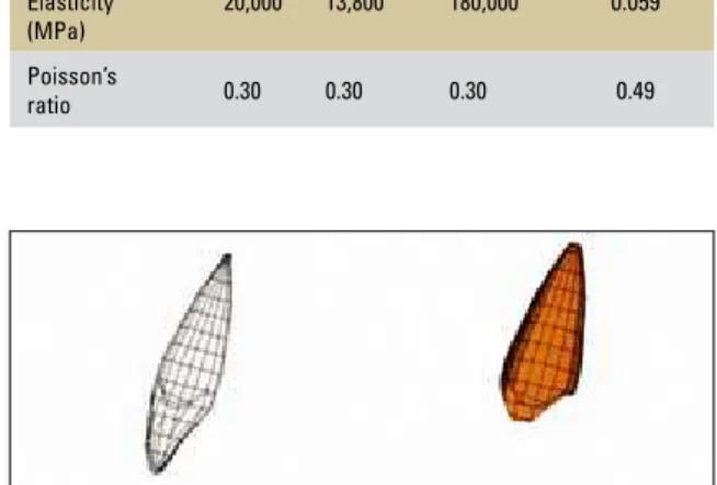
The tooth and alveolar cortical bone
The tooth27 and alveolar cortical bone were
discretized into Shell63 elements with a thick-ness of 0.25 mm. Figure 1 shows the model of the tooth and the alveolus using finite elements.
Periodontal ligament
The fibers of the periodontal ligament were discretized into Beam4 elements. The geometric properties attributed to the fibers of the peri-odontal ligament were established, noting that a large portion of the ligament (75%) is composed of collagen fibers arranged in bundles that extend from the root cementum to the alveolar cortical bone.5 Thus, to represent a bundle of fibers, we
assigned a value of 1 mm diameter to each fi-ber drawn in the model, which amounts to about 75% of intra-alveolar space filled with periodon-tal fibers. Figure 2 shows the connection between the tooth and alveolus through the periodontal fibers (A), with emphasis on the apical (B) and cervical (C) areas.
Properties Tooth Alveolus Bracket Periodontal Ligament
Modulus of Elasticity (MPa)
20,000 13,800 180,000 0.059 Poisson’s
ratio 0.30 0.30 0.30 0.49 TABLE 1 - Materials properties.
A
A
B
B
C
x
z y
x
z
y Bracket
The bracket was discretized into Shell63 ele-ments with a thickness of 1.40 mm, which cor-responds to the distance between the bracket base and the bracket slot.
Finite element model
The numerical model consists of 1,026 finite elements distributed among tooth, alveolus, peri-odontal fibers and bracket. Figure 3 shows the complete model and its respective reference axes. The tooth dimensions were obtained from the dental anatomy literature.27
Boundary conditions
Boundary conditions were applied in an at-tempt to replicate the conditions of the experi-ment conducted by Jones et al,10 who used a
de-vice that produced a constant 0.39 N force in the midpoint of the labial surfaces of one central inci-sor in ten experimental patients. The initial dis-placements were measured at a site in the incisal edge of the tooth crown with the aid of a laser beam measuring apparatus.
To reproduce the experimental conditions, the alveolar area of the model had its movements restricted in all directions, thereby limiting tooth movement within the periodontal space (Fig 4). Furthermore, a 0.39 N force was applied to the midpoint of the bracket in the model, as properly described by its directional components x, y, z.
RESuLtS And dISCuSSIOn Model validation
To validate the three-dimensional numerical model, tooth displacement results were compared
FIGURE 2 - Finite element model with the periodontal fibers connecting the tooth and alveolus.
x
z
y
with those obtained by Jones et al,10 in which the
mean displacement found for the central incisors of the ten experimental subjects was 0.0877 mm with a standard deviation of 0.0507.
To determine central incisor displacement dif-ferent values were assigned to the modulus of elas-ticity of the periodontal ligament fibers. With the value of 0.059 MPa, the incisal edge of the crown exhibited a tooth displacement of 0.089 mm (Fig 5). This value shows a difference of 1.46% com-pared with the value experimentally determined by Jones et al10 (0.087 mm). Despite this
differ-ence, it is possible to validate the results obtained with the finite element model by considering the morphological and geometric differences and ac-cording to the standard deviation value found ex-perimentally.
Based on this result it is valid to assign the val-ue of 0.059 MPa to the modulus of elasticity of the periodontal ligament fibers. The validation of this model allows further study through variations in load parameters (forces and moments).
Table 1 summarizes the values assigned to the properties of the materials used in the nu-merical model.
Study of axial stress
In addition to the results found for tooth dis-placements, the axial stress of the periodontal fi-bers was also obtained.
The classical concept of “optimal force” advo-cates that in order to produce orthodontic move-ment in such a manner as to allow the periodontal ligament and alveolar bone tissue to restore normal-ity, the root surface should undergo stress that is slightly higher than the stress exerted by the blood in the capillary vessel6 (capillary blood stress) of
15 to 20 mm Hg or equivalent to 20 to 26 gf/cm2
(0.0026 N/mm2 or 0.0026 MPa). Vessel
compres-sion hinders blood flow in areas of tencompres-sion and com-pression of the periodontal fibers.19 Kawarizadeh et
al12 used histological analysis to conclude that the
periodontal areas where greater stress arises from the application of orthodontic forces also promote a greater recruitment of bone tissue remodeling cells. Whenever an orthodontic force is applied to a tooth, the root moves closer to the alveolus wall, thereby stretching the periodontal ligaments on the side where the force was applied while compress-ing the opposite side. Thus, the vascular system that works naturally under local capillary blood stress is compressed and blood flow hindered. This process “injures the tissues” and promotes the release of in-flammatory response mediators, which ultimately trigger the process of bone remodeling.6,19
Based on this information, which links the stress to the process of bone remodeling, a crite-rion was established to compare the axial stress obtained from the numerical model with capil-lary blood stress.
FIGURE 4 - Boundary conditions applied to the model: force of 0.39 N in the bracket and restrictions to alveolar movements.
FIGURE 5 - Tooth displacement (mm) resulting from a 0.39 N load.
0
A B
x
z y Axial stress and their comparison
with capillary blood stress
Force on the crown = 0.39 N
The axial stress measured in the periodon-tal ligament fibers for a 0.39 N force applied to the bracket midpoint are illustrated in Figures 6 and 7A.
By observing the color scale and the magnitude of the axial stress along the periodontal fibers, the stress of greater magnitude clearly occurs in the cervical areas of the root. However, it is only in those cervical areas (labial and palatal) that stress magnitude exceeds capillary blood stress (0.0026 N/mm2). It is therefore possible to assert that, in
theory, it is only in those areas that the processes leading to bone remodeling occur.
On the other hand, stress of small magni-tude, i.e., lower than capillary blood stress, oc-cur in the apical root area along the periodon-tal fibers. Therefore, the magnitude of the ap-plied force can be considered negligible in light of the desired tooth movement and it therefore does not trigger the process of bone remodel-ing in this area.
Classification of resulting tooth movement The color scale indicates that in the api-cal area, the stress along the periodontal fibers are compressive stress (-) on the labial side
and tensile stress (+) on the palatal side. The labial surface of the cervical area displays ten-sile stress (+) and compressive stress (-) on the palatal side. This fact, in conjunction with the observation of axial stress and tooth displace-ment, make it possible to classify the different types of tooth movements. We can thus note a non-controlled tipping movement, whereby the rotation center lies between the signal transi-tion areas where the axial stress along the peri-odontal fibers are equal to zero, i.e., between the center of resistance and the root apex (Fig 7, A). This movement occurs when a force ap-plied to the crown moves the root apex in the opposite direction of the applied force.
Marcotte15 reports that in the center of
rota-tion, stress are equal to zero. We can thus, with the aid of the axial stress, categorize the types of tooth movement in light of the forces applied to the dental crown and the location of the rotation center of the tooth.
Figure 7B shows the direction, magnitude and orientation of the displacement achieved by ap-plying a force of 0.39 N, which further strength-ened the reliability of the information obtained through the axial stress. This figure shows that the displacements around the root apex are ori-ented in the opposite direction of those found in the incisal edge.
FIGURE 7 - View of the center of rotation under a 0.39 N load: A) axial stress, B) displacement.
0 .009893.019786.029679.039572.049455.059358.069252.079145.089038 -.004752
-.003689-.002626-.001583-.500E-03.583E-03.001626.002689.003752.004815
Crot Center of rotation
Fx
FIGURE 6 - Axial stress (N/mm²) resulting from a 0.39 N load.
Compressive stress
Compressive tensions
Center of rotation Crot
Traction tensions
Tensile stress
Force on the crown = 0.70 N
A 0.39 N force was efficient enough to pro-duce just a slight tipping movement in the upper central incisor, relative to the bone remodeling processes. In other words, this negligible force was capable of triggering the recruitment of re-modeling cells in the cervical area only. Proffit and Fields19 recommend forces between 0.30
N and 0.60 N to generate a tipping movement, while the magnitude of the force depends on the area of periodontal support. To identify the effects of excessive force, the magnitude of the applied force was increased to 0.70 N, a force considered to be above the force required for an efficient tipping movement of an upper central incisor.19 Figures 8 and 9A show the axial stress
resulting from a 0.70 N force.
By observing the color scale and the magnitude of the axial stress along the periodontal fibers it becomes clear that the stress of greater magnitude occur in the cervical area of the root, both in the tension and compression sides.
Unlike the previous case, however, the peri-odontal fibers that envelope almost the entire root area display stress levels which are higher than capillary blood stress (0.0026 N/mm2)
ex-cept in the area around the center of rotation (Fig 9, A).
Classification of resulting tooth movement Similarly to the previous case, the color scale shows that along the periodontal fibers the com-pressive stress (-) are in the labial area of the root apex and the tensile stress (+) are on the pala-tal side. On the labial surface of the cervical area the tensile stress (+) are on the labial side and the compressive stress (-) are on the palatal side, which discloses a uncontrolled tipping movement. Figure 9B shows the direction, magnitude and orientation of the displacement achieved by apply-ing a 0.70 N force, which strengthen the reliabil-ity of the information obtained through the axial stress. This figure shows that the displacements
around the root apex are also oriented in the op-posite direction of those found in the incisal edge.
Force and moment of force on the crown In cases of tooth movement with root move-ment control, it is advisable to apply to the bracket a force combined with a moment of force. With this procedure it is possible to gener-ate different types of tooth movement, includ-ing uprightinclud-ing, torque and translatory (bodily) movement. Control is exercised through a Mo-ment/Force ratio13,15,19 (M/F).
Thus, in order to obtain a translatory move-ment a 0.70 N force was applied, as in the previ-ous case, and a 7.5 Nmm moment of force applied around the y axis. In this case, the M/F ratio which produced the translatory movement was 10.7:1. The moment of force acts as a root torque to be applied to the bracket by a supposed rectangular orthodontic archwire.
Figure 10 shows the boundary condition applied to achieve the translatory movement with the si-multaneous loading of force and moment of force.
Figure 11 shows the axial stress obtained by simultaneously applying force and moment of force. By observing the color scale and the mag-nitude of the axial stress along the periodontal fibers it becomes clear that both exhibit nearly identical magnitude, distributed along the ver-tical axis of the root, on the labial and pala-tal surfaces. Several authors1,6,13,15,19 claim that
translatory movement entails a greater distri-bution of stress along the entire root length and that stress distribution along the root is relatively uniform.
In this case, nearly all of the root area surround-ed by the periodontal fibers displays stress levels above capillary blood stress (0.0026 N/mm2),
confirming that in order to achieve the translatory movement of the central incisor the loads should be those recommended by Proffit and Fields19,
A B
A B
F M
x
z
y
x
z
y
FIGURE 8 - Axial stress (N/mm²) resulting from a 0.70 N load.
the same M/F ratio (10.7:1) which determines the direction of tooth movement.
Figure 11 also shows, regarding the long axis of the tooth, that along the periodontal fibers the compressive stress (-) are on the palatal side and the tensile stress (+) are on the labial side.
Classification of resulting tooth movement Figure 12 shows the direction, magnitude and orientation of the displacement obtained as a result of force and moment of force applica-tion at a 10.7:1 ratio. The displacement occurs in parallel to the initial position, disclosing the
FIGURE 9 - View of the center of rotation under a 0.70 N load: A) axial stress, B) displacement.
FIGURE 10 - Boundary conditions applied to the model: 0.70 N force and 7.5 Nmm moment of force onto the bracket and restrictions to alveolar movements.
FIGURE 12 - Tooth displacement orientation resulting from the simultaneous loading of force and moment of force onto the bracket.
FIGURE 11 - Axial stress (N/mm²) resulting from simultaneously loading of force and moment of force.
Compressive stress
Compressive tensions
Center of rotation Tensile stress
Traction tensions
-.008531-.006621-.004713-.002905-.897E-03.001011.002919.004827.005735.006643 Crot
-.008531
-.006621-.004713-.002905-.897E-03.001011.002919.004827.005735.006643 0
.017757.035514.053271.071027.088784.106541.124296.142054.159611 Crot
Center of rotation
Fx
After
Before
F
M
F
M
Compressive stress Tensile stress
-.003512
-.002731-.001949-.001107-.386E-03.395E-03.001177.001958.002741.003521
0
x
z y
x
z y
translatory movement in light of the forces ap-plied while the center of rotation is located in an infinitely distant point from the tooth.
Another way to achieve translatory movement is through the application of a force to the center of resistance. For this it is necessary to locate the center of resistance of the tooth.
Application of force to the center of resistance (CRes)
The orthodontic literature agrees that the ap-plication of a force to the center of resistance of a tooth promotes translatory movement1,6,13,15,19.
For anatomical reasons, we do not apply, in con-ventional orthodontic treatment (force applied to the bracket), a force directly to the center of resistance, since the latter lies along the area of the root embedded in the alveolar bone. How-ever, by means of lever mechanics (cantilHow-ever, power arm)1,15 as well as in computer simulation
it is possible to accomplish this movement. The location of the center of resistance of the tooth was found to be at approximately 39.91% of the tooth height, measured from the alveolar crest. Burstone1 and Marcotte15 argue that the
cen-ter of resistance of a single-rooted tooth is located around 40% of the root height, also measured
from the alveolar crest. Some authors6,17 assert
that the center of resistance is located at 33% and others,13,26 at 66% of the root height.
Figure 13 shows the new boundary condi-tion applied to restrain all alveolar movements. The forces were applied perpendicularly to the long axis and directly to the center of resistance of the tooth.
To produce a translatory movement with a resultant force perpendicular to the longitudinal axis of the tooth at a force of 0.70 N in the hori-zontal direction (x), an additional 0.22 N force was added in the vertical direction (z).
Axial stress and capillary blood stress
Stress distribution appeared to be uniform along the root axis, as shown in Figure 14.
By observing the color scale and the magnitude of the axial stress along the periodontal fibers it is clear that the stress is distributed with virtually identical magnitude along the tooth axis. In this case, as in the previous case, the areas of the palatal and labial surfaces exhibit stress levels that exceed capillary blood stress. Observations of the color scale also revealed that, regarding axial tensions, the tensile stress (+) are on the labial surface and the compressive stress (-) are on the lingual surface.
FIGURE 13 - Boundary conditions resulting from the application of force to the center of resistance (CRes).
FIGURE 14 - Axial tensions (N/mm²) resulting from force applied to the center of resistance (CRes).
Fx Fx
Fy
Fy
-.003356
A B
Classification of resulting tooth movement Translatory movement, which occurred due to axial stress, was also confirmed by means of graphs showing the vectors and the total resulting displace-ment. Displacement occurred parallel to the tooth axis, evidencing the translatory movement (Figs 15, A and B), with the center of rotation located at infinity.
The methods used in the construction of this model served as the basis for building a complete model of a dental arch, which allows studies in-volving various orthodontic appliances.
COnCLuSIOnS
1) To enable quantification of the parameters involved in studies of orthodontic mechanics a three-dimensional numerical model of a maxillary central incisor was validated.
2) The value of E=0.059 MPa (0.059 N/mm2)
assigned to the modulus of elasticity of the peri-odontal ligament fibers enabled the validation of the numerical model.
3) The axial stress measured in the model show consistent values and assist in setting an appropriate value for use in computer simula-tions, by FEM.
4) The definition of a criterion that compares axial stress with the stress exerted by the blood in the capillary vessel (0.0026 N/mm2) made it
possible to predict which areas are likely to trigger the onset of bone remodeling.
5) A computer model enables the visualiza-tion and quantificavisualiza-tion of root and crown move-ments as well as the positioning of the center of rotation and the center of resistance of the tooth, which is of primary importance in determining tooth movement type.
6) The model presented in this study enables changes in loading parameters (forces and mo-ment of forces) and in boundary conditions, there-by allowing the creation of a complete model for a dental arch, to evaluation of different orthodontic mechanics alternatives.
FIGURE 15 - Translatory movement resulting from the application of force to the center of resis-tance (CRes): A) resulting vectors, B) resulting displacement.
Fx Fy
Fx Fy
0
Contact address
Maria Christina Thomé Pacheco Praça Philogomiro Lannes, 200 / 307 CEP: 29.060-740 – Vitória / ES, Brazil E-mail: [email protected]
Submitted: August 2008
Revised and accepted: October 2008 1. Burstone CJ. The biomechanics of tooth movement.
In: Kraus BS, Riedel RA, editors. Vistas in Orthodontics. Philadelphia: Lea & Febriger; 1962.
2. Cattaneo PM, Dalstra M, Melsen B. The inite element method: a tool to study orthodontic tooth movement. J Dent Res. 2005 May;84(5):428-33.
3. Chang YI, Shin SJ, Baek SH. Three-dimensional inite element analysis in distal en masse movement of the maxillary dentition with the multiloop edgewise archwire. Eur J Orthod. 2004 Jun;26(3):339-45.
4. Chen F, Terada K, Handa K. Anchorage effect of various shape palatal osseointegrated implants: a inite element study. Angle Orthod. 2005 May;75(3):378-85.
5. Dorow C, Schneider J, Sander FG. Finite element simulation of in vivo tooth mobility in comparison with experimental results. J Mech Med Biol. 2003;3(1):79-94.
6. Ferreira FV. Ortodontia: diagnóstico e planejamento clínico. 1ª ed. São Paulo: Artes Médicas; 1996.
7. Geramy A. Initial stress produced in the periodontal membrane by orthodontic loads in the presence of varying loss of alveolar bone: a three-dimensional inite element analysis. Eur J Orthod. 2002 Feb;24(1):21-33.
8. Geramy A. Optimization of unilateral overjet management: three-dimensional analysis by the inite element method. Angle Orthod. 2002 Dec;72(6):585-92.
9. Jeon PD, Turley PK, Ting K. Three-dimensional inite element analysis of stress in the periodontal ligament of the maxillary irst molar with simulated bone loss. Am J Orthod Dentofacial Orthop. 2001 May;119(5):498-504.
10. Jones ML, Hickman J, Middleton J, Knox J, Volp C. A validated inite element method study of orthodontic tooth movement in the human subject. J Orthod. 2001 Mar;28(1):29-38.
11. Katona TR, Qian H. A mechanism of noncontinuous supraosseous tooth eruption. Am J Orthod Dentofacial Orthop. 2001 Sep;120(3):263-71.
12. Kawarizadeh A, Bourauel C, Zhang D, Götz W, Jäger A. Correlation of stress and strain proiles and the distribution of osteoclastic cells induced by orthodontic loading in rat. Eur J Oral Sci. 2004 Apr;112(2):140-7.
REFEREnCES
13. Langlade M. Terapêutica ortodôntica. 3ª ed. São Paulo: Ed. Santos; 1995.
14. Lotti RS, Machado AW, Mazzieiro ET, Landre JRJ. Aplicabilidade cientíica do método dos elementos initos. Rev Dental Press Ortod Ortop Facial. 2006 abr;11(2):35-43. 15. Marcotte MR. Biomecânica em Ortodontia. 2ª ed. São Paulo:
Ed. Santos; 2003.
16. Melsen B, Cattaneo PM, Dalstra M, Kraft DC. The importance of force levels in relation to tooth movement. Semin Orthod. 2007 Dec;13(4):220-33.
17. Moyers RE. Ortodontia. 4ª ed. Rio de Janeiro: Guanabara Koogan; 1991.
18. Poppe M, Bourauel C, Jäger A. Determination of the elasticity parameters of the human periodontal ligament and the location of the center of resistance of single-rooted teeth a study of autopsy specimens and their conversion into inite element models. J Orofac Orthop. 2002 Sep;63(5):358-70. 19. Profit WR, Fields HW Jr. Ortodontia contemporânea. 3ª ed.
Rio de Janeiro: Guanabara Koogan; 2002.
20. Provatidis CG. A comparative FEM-study of tooth mobility using isotropic models of the periodontal ligament. Finite Element Method. Med Eng Phys. 2000 Jun;22(5):359-70. 21. Rees JS, Jacobsen PH. Elastic modulus of the periodontal
ligament. Biomaterials. 1997 Jul;18(14):995-9. 22. Rees JS. An investigation into the importance of the
periodontal ligament and alveolar bone as supporting structures in inite element studies. J Oral Rehabil. 2001 May;28(5):425-32.
23. Schneider J, Geiger M, Sander FG. Numerical experiments on long-time orthodontic tooth movement. Am J Orthod Dentofacial Orthop. 2002 Mar;121(3):257-65.
24. Swanson Analysis System. Solid modeling - user’s guide for revision 5.0. Houston: SAS, Inc.; 1994. v. 1.
25. Swanson Analysis System. Analysis user’s manual for revision 5.0. Houston: SAS, Inc.; 1992. v. 1-4.
26. Viazis AD. Atlas de Ortodontia: princípios e aplicações clínicas. 1ª ed. São Paulo: Ed. Santos; 1996.